

Dwin 2, Tran Scanner 2 Operating Instructions Manual

2
Operating Instructions
Printed in USA TranScanner 2
Read these instructions completely before operating this unit.
Contents subject to change without notice or obligation.
Rev. 9

Table of Contents
Safety Instructions .......................................
Specifications ............................................
Introduction ..............................................
3
5
5
Programming SL-8000 Remote Control to Operate TranScanner 2 5
Installation ............................................ 6
Quick Reference Remote Control Operation .................. 8
The Front Panel Controls.................................. 9
Using The Control Menus ................................... 9
Main Menu ............................................ 9
Video Control Menu.................................... 9
Input Menu ........................................... 10
Aspect Ratio Menu .................................... 10
Setup Menu ........................................... 10
Auto Input Select ................................. 11
Menu Timeout....................................... 11
Rename Inputs...................................... 11
Rename Aspect Ratios............................... 11
Display Setup...................................... 12
IR Setup........................................... 13
Relay Setup........................................ 14
OSG Setup.......................................... 14
TranScanner 2 Aspect Ratio Guide........................... 15
TranScanner 2 RS-232 Control............................... 17
Warranty .................................................. 18
- 2 of 18 -
Safety Instructions
WARNING
HAZARDOUS VOLTAGE
DO NOT OPEN
ATTENTION
COURANT ELECTRIQUE
NE PAS OUYRIR
!
CAN SHOCK, BURN OR CAUSE SEVERE INJURY OR DEATH. DO NOT
1. Read and apply all of the safety and operating instructions provided with your video equipment.
2. Keep all safety and operating instruction for future reference.
3. Unplug this video equipment from the wall outlet before cleaning. Never use liquid or aerosol cleaners.
Use only a damp cloth for cleaning.
4. Do not use any attachments or accessories not recommended by the manufacturer as they may cause
hazards.
5. Do not use this video equipment near water. Avoid placing it near a bathtub, kitchen sink, or laundry tub,
in a wet basement, or near a swimming pool.
6. Do not place this video equipment on an unstable cart, stand, or table. The video equipment may fall,
causing serious injury to a child or adult, and serious damage to the appliance. Use only with a cart or
stand recommended by the manufacturer. Wall or shelf mounting should follow the manufacturer's
instructions, and should use a mounting kit approved by the manufacturer.
6A. Move any appliance and cart combination with care. Quick stops, excessive force, and uneven surfaces
may cause the appliance and a cart to overturn.
7. Side openings in the cabinet are provided for ventilation, and to insure reliable operation of the video
equipment and protect it from overheating. These openings must not be blocked or covered. Never place
the video equipment on a bed, sofa, rug, or other similar surface that may block ventilation openings.
Never place this product near or over a radiator or heat register. Do not place this product in a built-in
installation such as a bookcase or rack unless proper ventilation is provided.
8. Operate only from the type of power source indicated on the marking label. If you are not sure of the type
of power supply to your home, consult your appliance dealer or local power company.
9. This unit is equipped with a three conductor polarized alternating-current line plug. This plug will fit into the
power outlet only one way. This is a safety feature. If you are unable to insert the plug fully into the outlet,
contact your electrician to replace your obsolete outlet. Do not defeat the safety purpose of the polarized
plug.
10. Route power-supply cords so that they will not be walked on or pinched by items placed on or against
them. Pay particular attention to cords at plugs, convenience receptacles, and the points where they exit
the products.
11. Protect your video equipment from lightning during a storm or when it is left unattended and unused for
long periods of time, unplug it from the wall outlet. This will prevent damage to the unit due to lightning
and power-line surges.
12. Do not overload wall outlets and extension cords as this can result in fire or electric shock.
13. Never push objects of any kind into this video equipment through cabinet slots as they may touch
dangerous voltage points or short out parts that could result in a fire or electric shock. Never spill liquid of
any kind on the video equipment.
14. Do not attempt to service this unit yourself as opening or removing cover may expose you to dangerous
voltages or other hazards. Refer all servicing to qualified service personnel.
15. Unplug this video equipment from the wall outlet, and refer servicing to qualified service personnel under
the following conditions:
a. When the power cord or plug is damaged or frayed.
b. If liquid has been spilled into the video equipment.
c. If the video equipment has been exposed to rain or water.
d. If the video equipment does not operate normally by following the operating instructions.
REMOVE THE TOP COVER. REFER SERVICING TO QUALIFIED PERSONNEL.
- 3 of 18 -
.

Adjust only those controls that are covered by the operating instructions as improper
adjustment of other controls may result in damage and will often require extensive work
by a qualified technician to restore the video equipment to normal operation.
e If the video equipment has been dropped or the cabinet has been damaged.
f. When the video equipment exhibits a distinct change in performance.
16. When replacement parts are required, be sure the service technician has used replacement parts
specified by the manufacturer that have the same characteristics as the original part. Unauthorized
substitutions may result in fire, electric shock, or other hazards.
17. Upon completion of any service or repairs to this video equipment, ask the service technician to perform
routine safety checks to determine that the system is in safe operating condition.
18. Do not place anything on the video equipment. heavy objects placed on any part of this system will cause
damage.
19. WARNING: To prevent fire or shock hazard, do not expose this appliance to rain or moisture.
20. CAUTION: TO PREVENT ELECTRIC SHOCK DO NOT USE THIS (POLARIZED) PLUG WITH AN
EXTENSION CORD, RECEPTACLE OR OTHER OUTLET UNLESS THE BLADES CAN BE FULLY
INSERTED TO PREVENT BLADE EXPOSURE.
NOTE 1: This equipment is designed to operate in the USA, Canada and other countries where the
broadcasting system and AC house current is exactly the same as in the USA and Canada.
IMPORTANT INFORMATION FOR THE USER
Note: This equipment has been tested and found to comply with the limits for a Class B digital device,
pursuant to Part 15 of the FCC Rules. The limits are designed to provide reasonable protection against
harmful interference in a residential installation. This equipment generates, uses and can radiate radio
frequency energy and, if not installed and used in accordance with the instructions, may cause harmful
interference to radio communication. However, there is no guarantee that harmful interference will not occur
in a particular installation. If this equipment does cause harmful interference to radio or television reception,
which can be determined by turning the equipment off and on, the user is encouraged to try to correct the
interference by one or more of the following measures:
• Reorient or relocate the receiving antenna.
• Increase the separation between the equipment and receiver.
• Connect the equipment into an outlet on a circuit different from that to which the receiver is connected.
• Consult the dealer or and experienced radio/TV technician for help.
This device complies with Part 15 of the FCC Rules. Operation is subject to the following two condition:
( 1 ) this device may not cause harmful interference, and ( 2 ) this device must accept interference received,
including interference that may cause undesired operation.
Note: Changes or modifications may cause this unit to fail to comply with Part 15 of the FCC Rules and may
void the user’s authority to operate the equipment.
- 4 of 18 -
S P E C I F I C A T I O N S
V i d e o I n p u t Te r m i n a l s (S e v e n I n p u t s )
Composite Video 1 Vp-p 75 Ohm
Component Video
Y: 1 Vp-p 75 Ohm
R-Y: 0.7 Vp-p 75 Ohm
B-Y: 0.7 Vp-p 75 Ohm
S-Video Y: 1 Vp-p 75 Ohm
C: 0.28Vp-p 75 Ohm
RGBS Input 0.7 Vp-p 75 Ohm
H & V Sync Input TTL Levels
RS232 Serial Computer Control
O u t p u t Te r m i n a l s
RGBS Outputs: 0.7 Vp-p 75 Ohm
Negative V & H/C SYNC Output:
1.5 Vp-p 75 Ohm
Horizontal Frequency: 31.5 - 64 kHz
Vertical Frequency: 50 or 60 Hz
P o w e r Re q u i r e m e n t s :
Model TranScanner 2-1 117 VAC 60Hz
Operating range (105 to 130) VAC
Model TranScanner 2-2 220 VAC 50Hz
Operating range (205 to 240) VAC
P o w e r Co n s u m p t i o n : 2 5 Watt Max
D i m e n s i o n s : ( W x H x D ) 1 7 " x 3 . 5 " x 1 3 "
A c c e s s o r i e s I n c l u d e d :
• Wireless Remote Control
• 6' AC Line Cord
• Operator's Manual
• 2.5mm DC Jack
O p t i o n a l Ac c e s s o r i e s :
• 19" Rack-mount Kit
Introduction
The TranScanner 2 is a variable line multiplier designed for use with projectors that have a scanning frequency
between 31.5kHz to 64kHz.
The TranScanner 2 cannot be used with a conventional television receiver or projector.
The projector or monitor used with the TranScanner 2 must have an RGB+S input and a horizontal scanning
frequency of between 31.5 kHz - 64 kHz.
Operating at this higher frequency, the TranScanner 2 multiplies the number of scanning lines, interpolating the
additional picture information from detail found in the original source material.
The scanning lines visible on conventional large screen displays are virtually eliminated and the new picture is
bright, colorful, and "film like".
The TranScanner 2 provides source switching for nine different inputs including three component ( Y, Cr, Cb ),
two composite video inputs, two S-VIDEO (Y/C) inputs and two RGB H & V Sync inputs.
An infrared wireless remote control with on-screen graphics selects the input source and adjusts all of the
operating controls.
Video controls include: contrast, brightness, color, tint, and sharpness.
Settings for each individual video input may be adjusted and stored separately in the controller's nonvolatile
memory. These settings will be restored each time that input is selected.
Programming SL-8000 Remote Control to Operate the TranScanner 2
The TranScanner 2 is shipped with a factory pre-programmed remote control.
1. Press the “AUX” and the “MUTE” buttons simultaneously. "SET" will appear on the LCD.
2. Enter the TranScanner 2’s brand code: “080”.
3. Press “AUX” button to complete the programming.
To operate other audio and video devices refer to the “SL-8000 Operating Manual”.
- 5 of 18 -
Installation
+12 VDC
100 mA
RY1 RY2
/
/
1
RED
GREEN BLUE
2
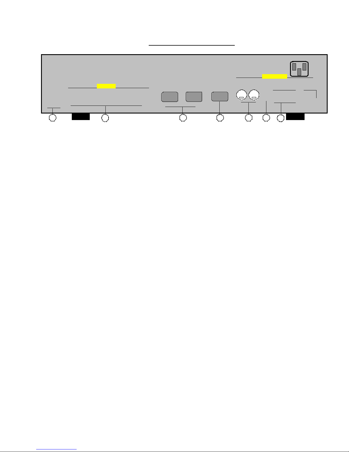
TranScanner 2 Rear Panel
OUTPUTS
H SYNC
2 2 2
2
2
2 3
1. Switched +12VDC Outputs, RY1, RY2 2.5mm DC Plug
2. Red, Green, Blue H, V and C Sync Outputs BNC
3. RGBS Computer Inputs 15 pin HD Socket
4. RS-232 Computer Input 9 pin D Plug
5. S-Video Inputs ( S1, S2 ) 4 pin Mini-Din
6. Composite Video Inputs ( V1, V2 ) RCA Type
7. Component Video Inputs (Y1, Cr1, Cb1) RCA Type
V SYNC
C SYNC
RGBS 1
INPUT
" " " " "
" " " " "
" " " " "
RGBS 2
INPUT
" " " " "
" " " " "
" " " " "
RS232
CONTROL
" " " " "
S1 S2
" " " "
4
5
(Y2, Cr2, Cb2)
(Y3, Cr3, Cb3)
" " " "
" " " "
VIDEO INPUTS
V1
Y1
1
1
1
1
V2
Y2
6
7
Cr1
1
1
Cr2
115 VAC 60 Hz
65 WATTS MAX.
Cb1
Y3
1
1
1
1
Cb2
Y3
Cr3
1
1
Cb3
1. SWITCHED +12VDC OUTPUTS
The TranScanner 2 has two switched +12 VDC outlets labeled as RY1 and RY2. These outlets may be used to
trigger a relay in an electric screen, projector lift or some other relay activated device. See “Relay Setup” menu
for more details.
2. RED, GREEN, BLUE AND H, V, C SYNC OUTPUTS
The output video signal from the TranScanner 2 to the display device is made via five BNC connectors for Red,
Green, Blue, H and V Sync. High quality 75 Ohm coaxial cables are recommended to connect the output of
TranScanner 2 to the display device.
The composite C Sync output may be used for displays that accept composite sync input.
3. RGBS INPUTS
The RGBS1 and RGBS2 inputs are provided for sources such as personal computers, HD tuners, video
cameras, graphic generators, and other video equipment with an RGB and Sync output.
Since these sources already operate at a horizontal frequency that is higher than conventional NTSC or PAL
video, the TranScanner 2 does not multiply their scan rate. However, the TranScanner 2 provides source
switching for these inputs, converts H & V Sync to composite Sync, provides control of contrast and brightness,
and amplifies RGB video signals to allow the use of longer cable lengths.
The TranScanner 2 will automatically switch to a RGB input if proper Horizontal or Composite Sync is applied at
pin 13 of the D-15 RGB connector.
The pin assignments for the 15 PIN "D" connector are as follows:
1. Red
2. Green
- 6 of 18 -
 Loading...