

Page 1
Operating Instructions
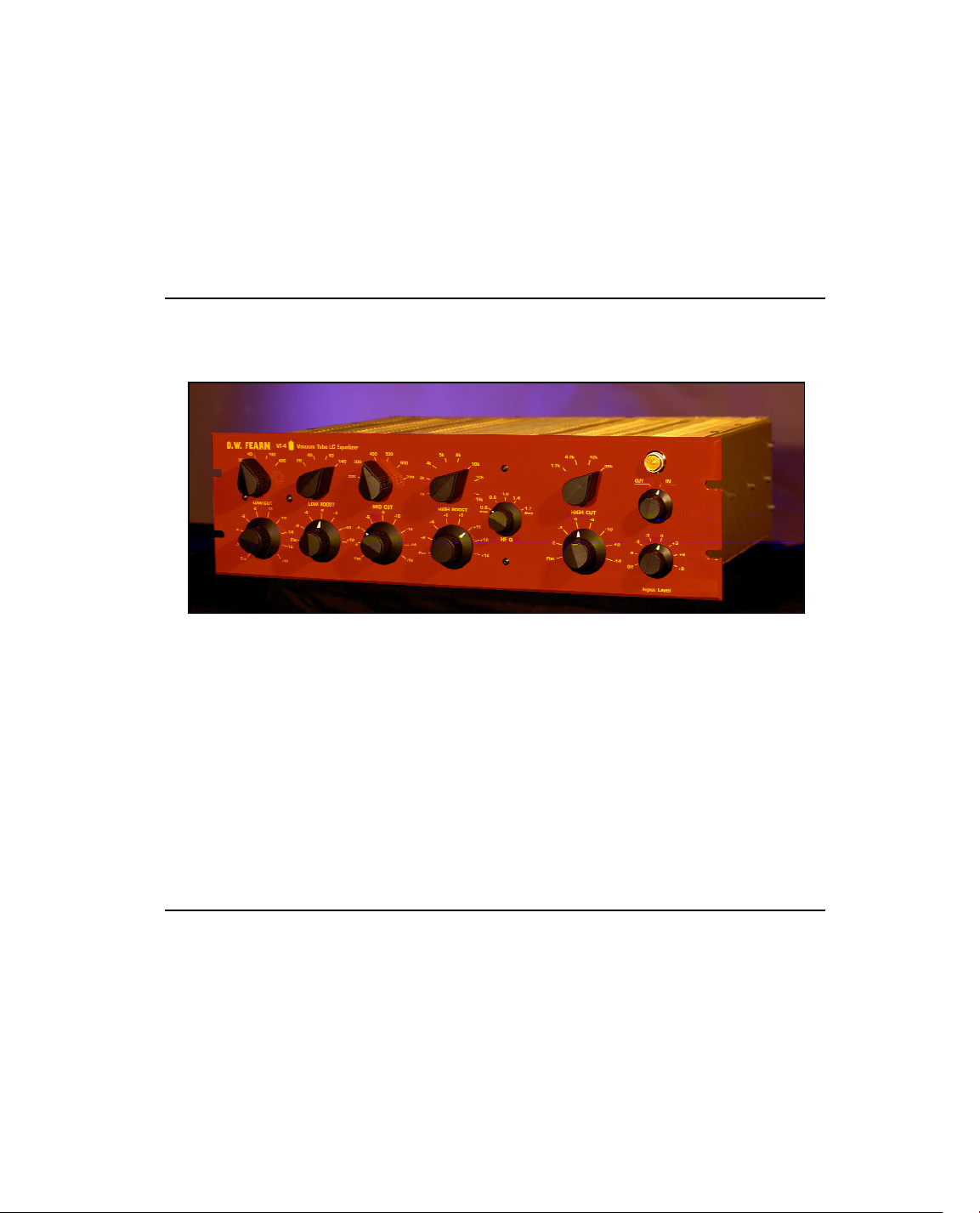
D.W. FEARN
VT-4 Vacuum Tube LC Equalizer
Page 2

HOW TO CONTACT US:
Telephone: 610-793-2526
Fax: 610-793-1479
Mail: P.O. Box 57, Pocopson, PA 19366 U.S.A.
Shipping Address: 182 Bragg Hill Road, West Chester, PA 19382 U.S.A.
e-mail: dwfearn@dwfearn.com
Web: www.dwfearn.com
Page 3

D.W. Fearn shall not be liable for technical or editorial errors or omissions in this
manual, nor for incidental or consequential damages resulting from the use of this
material.
This instruction manual contains information protected by copyright. No part of this
manual may be photocopied or reproduced in any form without prior written consent
from D.W. Fearn.
Copyright © 2000 D.W. Fearn & Associates
Page 4

TABLE OF CONTENTS
Warranty.................................................................................7
Specifications ........................................................................9
Features ...............................................................................11
History of the VT-4 ..............................................................13
Description ...........................................................................15
Installation ..........................................................................17
Operation .............................................................................19
Theory .................................................................................21
Maintenance ........................................................................23
D.W. Fearn VT-4 Vacuum Tube LC Equalizer 5
Page 5

LIMITED 5-YEAR WARRANTY
During the warranty period, D.W. Fearn will, at no additional charge, repair or replace
defective parts with new parts.
This warranty does not extend to any VT-4 that has been damaged or rendered defective as a result of accident, misuse, or abuse; by the use of parts not manufactured or
supplied by D.W. Fearn; or by unauthorized modification of the VT-4. Vacuum tubes
are excepted from the 5-year warranty, but are warranted for 90 days from date of
purchase.
Except as expressly set forth in this Warranty, D.W. Fearn makes no other warranties,
express or implied, including any implied warranty of merchantability and fitness for
a particular purpose.
D.W. Fearn VT-4 Vacuum Tube LC Equalizer 7
Page 6

SPECIFICATIONS
(All measurements made with +4dBm in and out, Eq switched in
but all controls set to flat.)
Input 600 ohms
Input Load
Impedance 40k ohms
Minimum Input
Level -20 dBm nominal
Maximum Input
Level @ 20 cps +25 dB
Gain 0 dB
Frequency
Response ± 0.5 dB 20 cps to 20 kc
-3 dB @ 0.5 cps & 80 kc
THD + Noise <0.10% 20 cps to 20 kc
Intermodulation
Distortion SMPTE: <0.80%
Signal to
Noise Ratio 82 dB minimum
Output low-Z, transformer balanced
Maximum
Output Level +22 dBm unterminated
Power
Requirements 100, 120, or 220 VAC
50/60Hz, 25 W
Dimensions 19” (48.26cm) W
5.25” (13.34cm) H
9” (22.86cm) D (VT-2 13” 22.9cm)
Weight 14 lbs (6.35 kg)
Note: Throughout this manual, frequency is specified in cps (cycles per second) or kc
(kilocycles per second). These units of measurement correspond to Hz and kHz respectively. Specifications subject to change without notice
D.W. Fearn VT-4 Vacuum Tube LC Equalizer 9
Page 7

EQ FEATURES
(All controls are independent and can be used in any combination)
Low Cut at 30, 40, 100, or 400 Hz,
0 to -18 dB shelving in 2 dB steps
Low Boost at 20, 40, 60,
0 to 12 dB shelving in 2 dB steps
Mid Cut at 200, 300, 400, 500, 600,
or 700 Hz, 0 to -16 dB in 2 dB steps
High Boost at 2, 3, 4, 5, 8, 10, 12, or 16 kHz,
0 to 14 dB in 2 dB steps
High Bandwidth Q of 0.6, 0.8, 1.0, 1.4,
High Frequency Cut at 1.7, 4, 10, or 28 kHz,
0 to -14 dB shelving in 2 dB steps
Gain adjustable from -9 to +9 dB,
referenced to +4 dBm, in 3 dB steps
or 140 Hz,
or 1.7
Note: Throughout this manual, frequency is specified in cps (cycles per second) or kc
(kilocycles per second). These units of measurement correspond to Hz and kHz respec-
tively. Specifications subject to change without notice
D.W. Fearn VT-4 Vacuum Tube LC Equalizer 11
Page 8

HISTORY OF THE VT-4
Throughout my career in recording, there have always been a few equalizers that stood out as being
exceptional. Among my favorites are the 1970s-era Neve input-strip eqs, and the Trident CB9066 parametric. I began my equalizer development project by first building a series of test circuits, using all
the various tone-modification techniques. After listening to a wide variety of equalization circuits, it
was obvious to me that the passive inductor-capacitor (LC) circuit was the one that sounded the most
musical and natural to me.
In thinking about how I use equalization, I realized that having simultaneous boost and cut at the low
and end frequencies was often very useful. For mid-frequencies, I found that I always cut, usually
around 400 Hz, and never had any reason to boost in that range. If I were using a parametric equalizer, I invariably tended to use the low-Q (broadest) settings, and if I had a choice between shelving or
peaking on the high and low end, I almost always prefered the shelving curve.
So the VT-4 was designed around those preferences -- low-Q curves, shelving, with simultaneous boost
and cut, mid-range cut but not boost, and using passive LC circuitry.
The amplification stages would be vacuum tube, and since the VT-1/VT-2 mic preamps have had such
a gratifying acceptance in the world of recording, it was important to preserve the same sonic characteristics that distinquished the preamps. I decided to try the Svetlana 6N1P dual triode, and was pleasantly surprised to find that it is a wonderful-sounding tube, with many of the same sonic characteristics as the 6072A used in my preamps. The active tube circuitry fell into place with relatively little
effort. Now it was time to make the equalization circuitry work the way I wanted.
To start, I used the filter design tables developed by Bell Labs in the 1930s. That got the project off
the ground and it was starting to sound pretty good. For several months, I listened to a variety of music
through a prototype equalizer while I was working on other things, and gradually narrowed-in on what
sounded really good and what didn’t. I would frequently have a box of capacitors and clip leads next
to the prototype and often clipped-in a different value here or there and continued listening.
Eventually, the final frequencies, curves, control operation, etc. was determined. To this day, I have
only a vague idea of what the actual curves look like. Equalizers, like all audio equipment, should
please your ears, not your test equipment.
My experience with Jensen Transformers Inc. was so positive that I knew from the beginning that I
would utilize their products. The first couple of prototypes used inductors that I wound myself, but for
production units more-consistent inductors would be necessary. Jensen agreed to manufacture the
necessary inductors to my specifications, and the quality of the parts is astounding.
D.W. Fearn VT-4 Vacuum Tube LC Equalizer 13
Page 9

DESCRIPTION
The Model VT-4 Vacuum Tube LC Equalizer is designed to provide recording professionals with a sonically superior outboard processing device. It is typically used in sound recording studios for modifying the frequency response characterisics of an individual track. A pair of VT-4s can be used to
process a stereo mix with precise matching between units.
It is designed for use in the professional recording environment. It accepts all standard low-impedance
(nominally 600 ohm) line-level (nominally +4 dBm) signals. The output is line-level (+4 dBm) lowimpedance, transformer-isolated and designed to feed bridging inputs. It is built to sound great for a
long time, with top quality parts used throughout; all the transformers, inductors and many other components are custom-made for the VT-4.
All power supplies are solid state and fully regulated. All rotary controls use high-quality silver-contact
switches for precise repeatability and matching between units.
Much of the circuitry for the VT-4 is based on the highly-successful D.W. Fearn VT-1 and VT-2 Vacuum
Tube Microphone Preamplifiers. Since line-level signals are utilized in the VT-4, Class-A Svetlana
6N1P dual triodes are used for all amplifier stages. The input transformer, inductors in the passive
equalization circuitry, and the output transformer are custom-made for us by Jensen Transformers
Inc.
The VT-4 is not mass-produced. Each one is hand-made and meticulously tested and listened to before
shipment to the customer.
The philosophy behind the VT-4 is: use only the best components in an optimized circuit, and build it
with pride and precision. The VT-4 is designed and built to perform in your studio for decades to come.
D.W. Fearn VT-4 Vacuum Tube LC Equalizer 15
Page 10

3.
INSTALLATION
The VT-4 is carefully packed for shipment and it should survive all but the most brutal
handling. If there is any damage, keep the shipping material for use during any possible
claim for damage with the shipper.
Included in the box:
1) The VT-4 Equalizer
2) Line cord
3) This instruction manual
Mounting
The VT-4 is designed for installation in a standard 19 inch rack. It requires 5.25 inches
of vertical space, but additional spacing between it and adjacent equipment is recom-
mended for adequate cooling. Ideally, a ventilated panel at least 1 rack unit high (1.25
inches) should be installed above and below the VT-4 (and around any other heat produc-
ing equipment for that matter). Be sure the bottom vent slots are not blocked. It is essen-
tial that air can flow into the bottom and out of the top of the VT-4. Equipment that runs
cool can last for a very long time.
In tight equipment enclosures, be sure there is adequate air flow. Forced air cooling will
benefit all your equipment.
The VT-4 can also be used without a rack, placed on a table, counter, or even on the
floor. Optional rubber feet are available, when requested at the time of the order.
Moderate electrical and magnetic fields in the vicinity of the VT-4 should not cause any
degradation in noise performance, due to the well-shielded construction, but proximity to
devices with motors or large power transformers (i.e. tape machines or power amps)
should be avoided.
Although the vacuum tubes in the VT-4 are selected for minimum microphonic
response, it is a good practice to avoid mounting locations that subject the VT-4 to very
high sound or vibration levels.
D.W. Fearn VT-4 Vacuum Tube LC Equalizer 17
Page 11

Input and Output Connections
Gold-plated XLR connectors are used for inputs and outputs. The input connector is
female and the output male.
All connectors are wired according to AES standard: pin 1 is ground (shield), pin 2 is
“high” or “+,” and pin 3 is “low” or “-.” Apositive voltage on pin 2 of the input will result
in a positive voltage on pin 2 of the output
Grounding and Shields
A full discussion of proper studio wiring schemes is beyond the scope of this manual,
but, in general, the Input mating XLR connector must have the cable shield connected to
pin 1.
Whether the shield is connected to pin 1 of the output connector depends on the stan-
dard in your studio. The shield should be connected to ground at only one end of the out-
put cable; however, although not recommended, the shields can often be connected at both
ends without a problem.
Input
Since the input cable will be carrying very high-quality audio, it is important that a
well-shielded cable is used.
Output
The output of the VT-4 is line level, transformer balanced. Note that vacuum tube
equipment is more sensitive to load impedance than solid state units. The VT-4 design
was optimized for feeding a balanced bridging input (20k ohms or greater). When feed-
ing a 600 ohm load, there may be a slight degradation of some of the specifications. In
modern studio equipment, bridging line inputs are universal. If the device being fed by
the VT-4 has an input termination switch, that switch should be in the “off” position.
The VT-4 can feed balanced or unbalanced inputs with no need for any modification in
output wiring. Either pin 2 or 3 can be grounded, although pin 2 is normally used as the
”hot” and pin 3 grounded in unbalanced configurations.
18 D.W. Fearn VT-4 Vacuum Tube LC Equalizer
Page 12

4.
OPERA TION
The use of most controls on the VT-4 Equalizer is self-explanatory. One feature
to note is that controls may be used in any combination. For example, use of both the
Low Cut and Low Boost controls at the same time can result in some extraordinary
effects. This also applies to the High Boost and High Cut.
The Mid-Cut control has a relatively low Q at minimal sttenuation settings.
Thus, the band covered is quite broad. As the Mid Cut control is advanced, the Q
becomes sharper and effects the selected frequency more narrowly. Low attenuation
settings (-2 to -6) are effective for removing some of the “mid-range muddle” than can
degrade a recording. The higher settings are useful to null-out an annoying resonance.
The High Cut control is useful for reducing noise. The highest frequency setting
(28 kHz) is particulary useful for digital recording. Attenuation in this range may help
avoid effects common with anti-aliasing filters in A-D converters.
The Input control allows processing of a wide range of input levels. Also,
extreme amounts of boost could overload the input of the device being feed by the VT-
4. Reducing the Input control setting may be helpful in this circumstance. It also
allows the overall output level of the VT-4 to be reduced to provide a better level to the
recorder. Settings above the “0” position are useful when processing signals from semi-
pro gear that typically have a lower output level.
Like all recording gear, there is no right or wrong when using the VT-4. Use
your ears and select settings that achieve your sonic goal. But avoid boosting frequen-
cies when there is no effect (such as boosting the extreme highs on a bass guitar), since
doing so may only increase noise.
D.W. Fearn VT-4 Vacuum Tube LC Equalizer 19
Page 13

5.
THEORY OF OPERATION
Input section
Line level (600 ohm source impedance, balanced, +4 dBm nominal) audio enters
through the XLR-3 female INPUT connector to the seven-position Input level control.
The input is balanced-bridging, with an impedance of 40k ohms. The input transformer
is made by Jensen Transformers Inc. The input switch is a passive pad on the primary of
input transformer. A two-stage Class-A triode amplifer utilizing 6N1P vacuum tubes pro-
vides isolation from the input of the VT-4 to the passive LC equalization circuitry.
Equalization section
All equalization is accomplished with passive LC (inductor/capacitor) circuitry.
The inductors are custom-made for the VT-4 by Jensen Transformers Inc. All capcitors
are polystyrene or polypropylene types. The rotary switches are semi-sealed, silver-con-
tact types selected for quiet operation and long life.
Output section
The output amplifier is similar to the Input section, using a two-stage, Class-A 6N1P
triode amplifier with a cathode-follower output. The output is tranformer-balanced, using
a custom-made Jensen transformer. The output is optimized for feeding bridging inputs,
which are standard in the recording industry. Either a balanced or unbalanced source may
be fed.
ower Supplies
P
Both the filament and B+ power supplies are solid-state and fully regulated. The fila-
ments are operated on regulated DC. A custom-made toroidal power transformer supplies
the proper voltages and has primary windings for 100, 110-130, or 220-240 VAC. The
power switch, mains voltage selector (115/230VAC), and line fuse are on the back panel.
D.W. Fearn VT-4 Vacuum Tube LC Equalizer 21
Page 14

6.
MAINTENANCE
The VT-4 is built with only the highest quality parts and will prove to be extremely reli-
able. Vacuum tubes and electrolytic capacitors, however, have a finite useful life and must
be replaced eventually.
op Cover Removal
T
Removing the top cover allows access to the vacuum tubes. Phillips-head screws must
be removed. When replacing the cover, position it so that the slotted ventillation holes are
over the tubes (towards the back ).
Vacuum Tubes
Four 6N1P tubes are used in the VT-4. V101 and V201 are the input stage and V102
and V202 are the output stages. Tube life is difficult to predict, but it will probably be
measured in years. Catastrophic tube failure is rare with this type of device, but a gradual
increase in noise, microphonics, distortion, or a reduction in headroom, should indicate
the need for replacement. It is recommended that you periodically perform a quick noise
and distortion check on the VT-4 and compare the results to previous measurements.
Replacement tubes may be obtained from us (tested and graded for low-noise and micro-
phonics), or other suppliers.
D.W. Fearn VT-4 Vacuum Tube LC Equalizer 23
Page 15

Rotary Switc hes
The rotary switches in the VT-4 were chosen for their self-cleaning property. In a clean
environment (non-smoking, with frequent room and equipment vacuum cleaning), and
with regular use, the rotary switches should require little attention for years. But if clean-
ing becomes necessary, we recommend using De-Oxit (Caig Laboratories). Follow the
instructions provided with the product.
If the switches are not used regularly, oxide and dirt can build up on the contacts. Rotate
the switches through their range a few times on a weekly basis to keep them clean.
arranty Repair
W
If the VT-4 should develop a problem during the five-year warranty period, call the fac-
tory for return shipping instructions. We will repair and return your VT-4 quickly. Note
that the warranty does not cover vacuum tubes, which must be periodically replaced.
24 D.W. Fearn VT-4 Vacuum Tube LC Equalizer
 Loading...