

Page 1
INSTALLATION INSTRUCTIONS
269 –LED BATH
WS-26922/WS-26930/WS-26940
CAUTION: TO PREVENT ELECTRICAL SHOCK, ENSURE ELECTRICITY HAS BEEN TURNED OFF AT THE CIRCUIT BREAKER BEFORE BEGINNING.
- Read all instructions before installing.
- System is intended for installation by a licensed electrician in accordance with the National Electrical Code (NEC) and local regulations.
- When handling the fixture, do not apply pressure to the LEDs. Hold the fixture by the base only.
- Retain installation instructions for future maintenance reference.
WARNING: All parts must be used as indicated in these instructions. This product is designed for use only with the supplied parts and/or accessories designated
for use by dweLED. Substitution of parts or accessories not designated for use with this product by dweLED could result in personal injury or property damage,
and will void the warranty. Contact an authorized dealer or the manufacturer if any parts are damaged or missing.
MAINTENANCE NOTE: Coastal conditions may cause mineral and residue build-up on the fixture. We recommend that customers in coastal areas clean all
external surfaces of the fixture once every two weeks with a wet cloth.
MISE EN GARDE: Pour éviter tout choc électrique, assurez-vous que le disjoncteur soit mis hors tension avant de commencer.
- Lisez toutes les instructions avant l’installation.
- Le système doit être installé par un électricien licensié conformément au code national de l’électricité (NEC), et également aux règlements locaux.
- Lors de la manipulation du luminaire, n’appuyez pas sur les LED. Tenez-le uniquement par la base.
ATTENTION: Toutes les pièces doivent être utilisées comme indiqué dans ces instructions. Ce produit est conçu pour être utilisé seulement avec les pièces et/ou
accessoires fournis pour être utilisés avec les produits dweLED. Remplacer des pièces ou accessoires non conçus pour ce produit dweLED pourrait causer des
dommages corporels ou matériels et pourrait également causer l’annulation de la garantie. Veuillez contacter un revendeur autorisé ou le fabricant si des pièces
manquent ou sont endommagées.
NOTE D’ENTRETIEN: Les conditions côtières peut causer une accumulation de minéraux et de résidue sur le luminaire. Nous recommendons aux clients qui
resident dans les zones côtières de nettoyer toutes les surfaces externes du luminaire une fois toutes les deux semaines avec un chiffon humide.
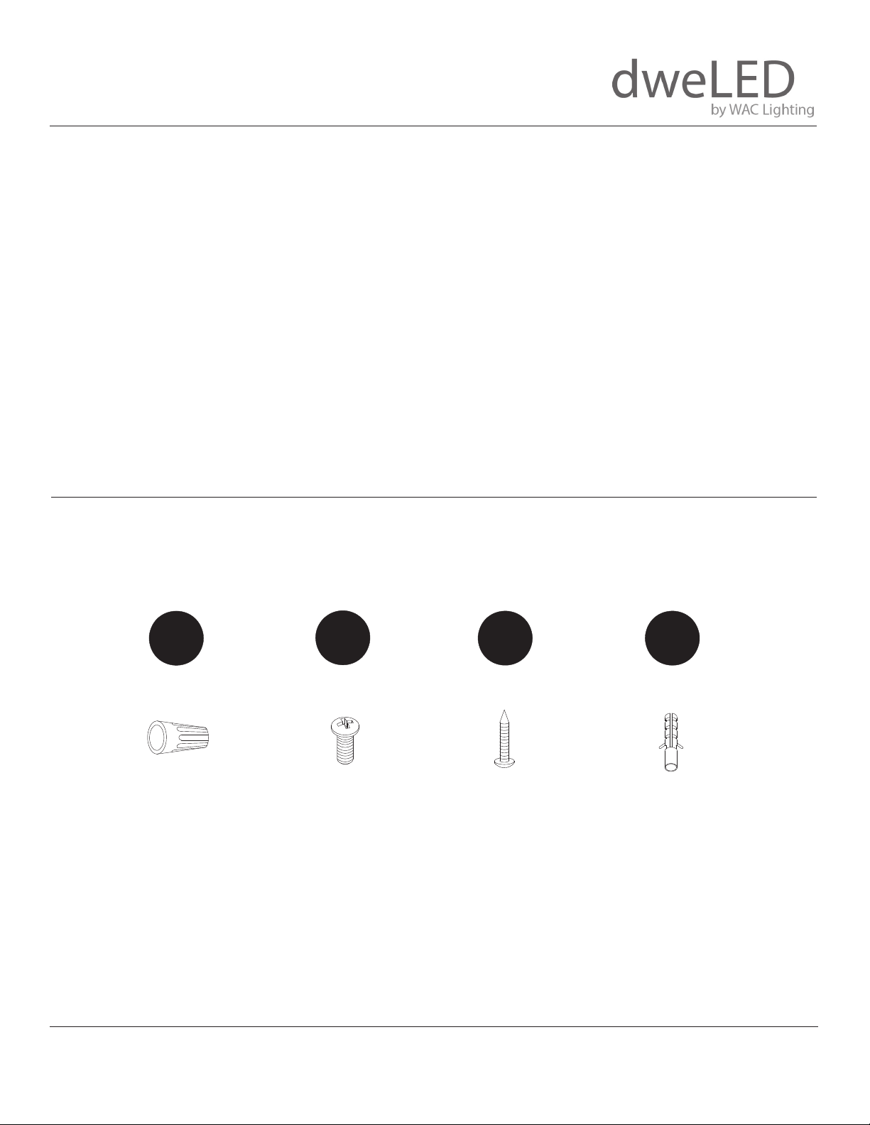
HARDWARE
A
Wire Connector
Qty: 3pcs+1 Extra
B
Mounting Screw
Qty: 1 Extra
5/32-32x5/16
C
Wood Screw
Qty: 2pcs+1 Extra
Ø4x22
D
Plastic Anchor
Qty: 2pcs+1 Extra
Ø7.5x24
dweLED.com
Phone (800) 526.2588
Fax (800) 526.2585
dweLED retains the right to modify the design of our products at any time as part of the company's continuous impro
Headquarters/Eastern Distribution Center
44 Harbor Park Drive
Port Washington, NY 11050
Central Distribution Center
1600 Distribution Ct
Lithia Springs, GA 30122
Western Distribution Center
1750 Archibald Avenue
Ontario, CA 91760
vement program. Feb 2019 1
Page 2
INSTALLATION INSTRUCTIONS
269 –LED BATH
WS-26922/WS-26930/WS-26940
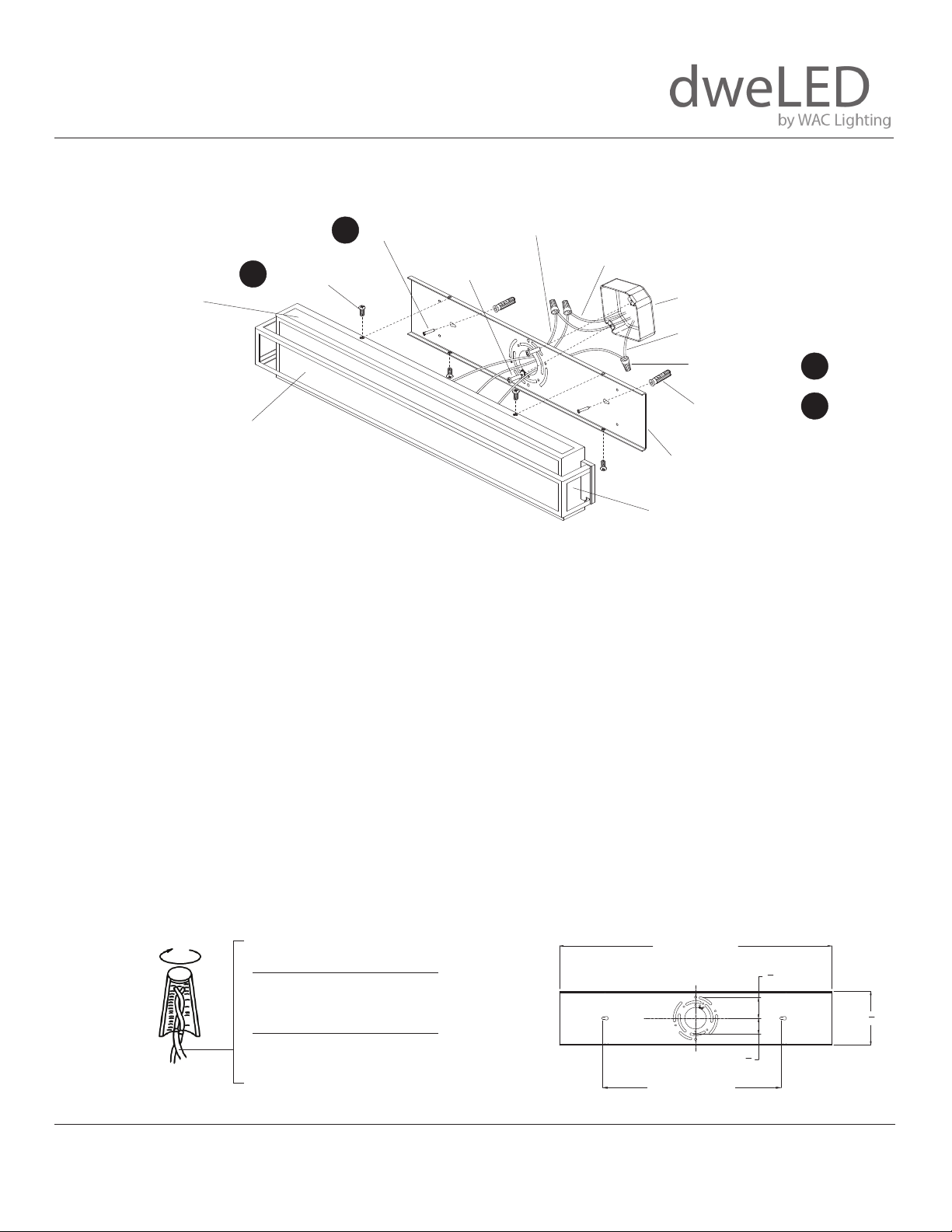
FIG. 1
White Wire
Black Wire
Junction Box
SIDE GLASS
B
Mounting Screw
C
Wood Screw
Junction Box
Screw
(RPL-GLA-26922-02)
(RPL-GLA-26930-02)
Bare Copper Ground Wire
(RPL-GLA-26940-02)
Wire Connector
Plastic Anchor
A
D
FRONT GLASS
(RPL-GLA-26922-01)
(RPL-GLA-26930-01)
Mounng Back Plate
(RPL-GLA-26940-01)
Lamp Body
PREPARATION
1. Shut o the power at the circuit breaker and remove existing xture, including the crossbar.
2. Carefully unpack your new xture and lay out all the parts on a clear area. Be careful not to lose any small parts necessary for installation.
MOUNTING THE FIXTURE (Fig. 1)
3. Remove the mounting screw (B) from the fixture.
4. Drill holes in the wall aligned with the key holes located on the back plate. Insert the plastic anchor (D).
5. Secure the mounting back plate to the junction box using the screws provided with the junction box. Fasten the back plate to the wall
with the plastic anchors using the wood screws (C) provided.
NOTE: The side of the mounting plate marked “GND” must face out.
CONNECTING THE WIRES (Fig. 2)
6. Connect the xture’s input wires to junction box wires as shown (Fig. 2). Make sure that all wire connectors (A) are secure. If your outlet
box has a green or bare copper ground wire, connect the xture’s ground wire to it. Otherwise, connect the xture’s ground wire directly
to the back plate using the green screw provided. After wires are connected, tuck them carefully inside the junction box.
COMPLETING THE INSTALLATION
7. Secure the xture to the mounting back plate using the mounting screw (B).
FIG. 2 Wiring
dweLED.com
Phone (800) 526.2588
Fax (800) 526.2585
dweLED retains the right to modify the design of our products at any time as part of the company's continuous impro
Fixture Wires
Black or
Smooth
Fixture Wires
White or
Ribbed
Fixture Wires
Bare wire
(Ground)
Headquarters/Eastern Distribution Center
44 Harbor Park Drive
Port Washington, NY 11050
House Wires
Black
(Hot)
House Wires
White
(Neutral)
House Wires
Green or Bare Copper
(Ground)
WS-26922&WS26930&WS26940 Back Plate
WS-26922 : 15 1/8"
WS-26930 : 22 7/8"
WS-26940 : 32 1/4"
WS-26922:8 7/10"
WS-26930:15"
WS-26940:19 7/10"
Central Distribution Center
1600 Distribution Ct
Lithia Springs, GA 30122
vement program. Feb 2019 2
3
"
1
4
3
"
1
8
Western Distribution Center
1750 Archibald Avenue
Ontario, CA 91760
1
4
"
2
 Loading...