

Page 1
Page 2
Contents
• Introduction.............................................. 1
• Safety Precautions..................................... 2
• Overview .................................................. 3
• Characteristics.......................................... 4
• Product Description Transmitter................... 5
• Product Description Reciver........................ 6
• Operation................................................. 7
• Antenna Positioning.................................. 8
• Functions................................................. 8-11
• Maintenance............................................ 12
• Troubleshooting ....................................... 12
• Technical Specications............................. 13
• Country-specic operating license.............. 14
• Included Accessories................................. 14
• Notes....................................................... 15
Page 3
1
Introduction
Congratulations on purchasing the DC-Link video transmission system. Please read this
manual carefully before operating your product, and ensure it is kept in a safe place.
The technology contained in this product, including the device itself as well as related
software and trademarks, is protected by law. Any duplication or reproduction with
out the written permission of the copyright owner is prohibited, in part or in full. All
third-party brands or copyrights mentioned in this manual are the property of their
respective owners.
This product has a limited warranty of one year. Warranty may be voided by:
• Physical damage of the product
• Any damage caused by improper use, maintenance or storage
• Damage resulting from the use of incorrect power supplies
• Damage not related to the design of the product or the quality of
its manufacture
EN
Page 4
2
Safety Precautions
The Video Transmission System
Do not block or obstruct air vents, as this may cause short circuits, re or electric
shocks. Turn the device off immediately if it comes into contact with liquids.
The Power Supply
The device may be used with batteries or AC-DC power supplies of the voltage speci-
ed on the device or in the enclosed documentation.
If batteries are used, please ensure that the batteries are compatible and have no
cracks or leaks.
Please use the enclosed power adapter. When using a third-party power adapter,
please ensure that the adapter conforms to the specications of the device and has the
correct polarity.
Remove the power supply if:
• The device will not be used for an extended period of time
• The power cable is damaged
• The exterior of the device is damaged.
Operating Environments
• Due to current regulations governing the use of radio-based systems, this
device is authorised for indoor use with the pre-installed channels ve and six (by law,
“indoor use” is dened as use in a building or similar location in which the shielding will
typically provide the necessary attenuation).
• Do not place the device on metallic surfaces, to ensure effective data transfer.
• Do not place the device on dirty or damp surfaces.
• Do not use the device in the proximity of water or in high humidity, near open
res or gas pipes, or near electrical mains.
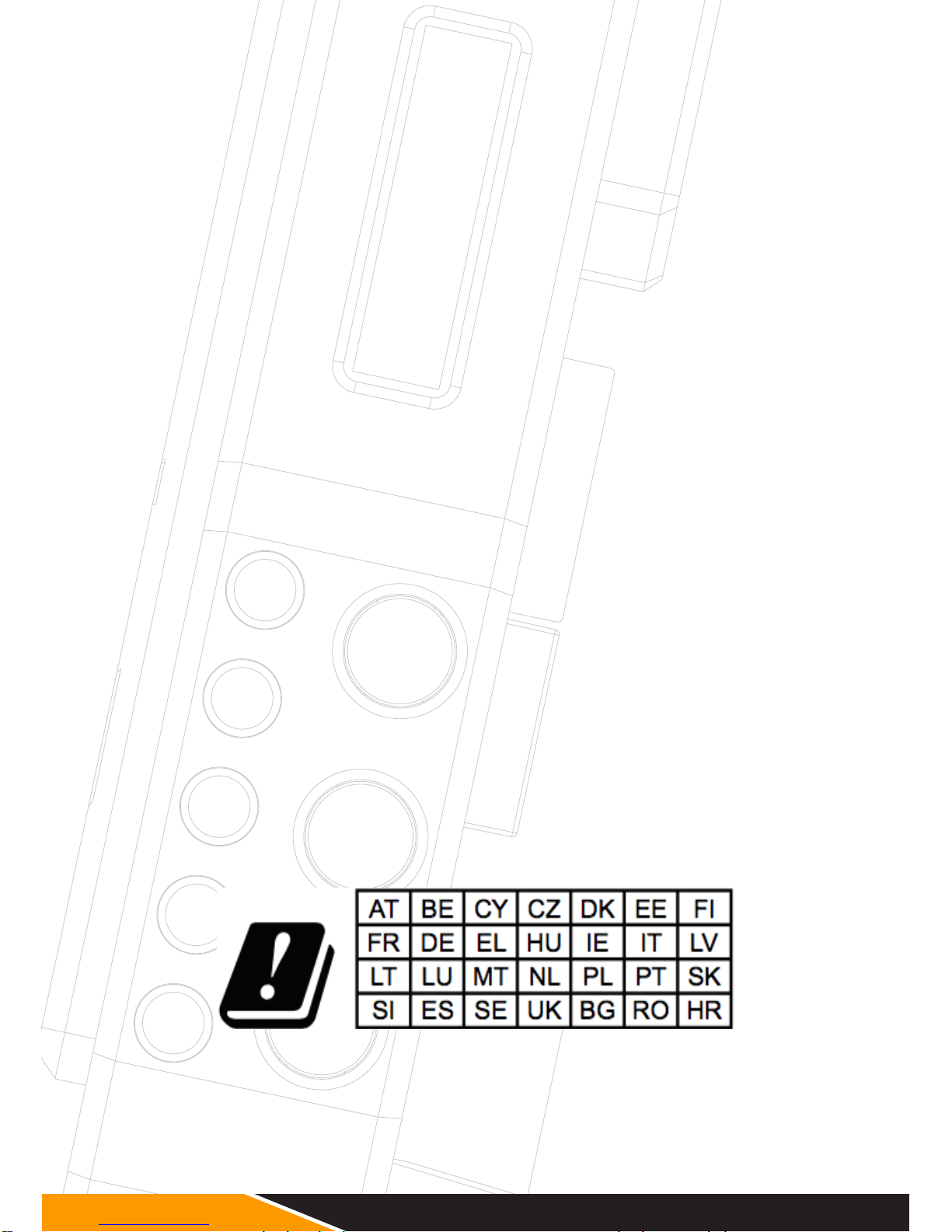
In all EU member states, operation of 5150-5250MHz
is restricted to indoor use only.
Page 5
3
Overview
The DC-Link- ULR1/LR2 is a high-performance WHDI video transmission system which
transmits uncompressed video and audio signals up to 1200m(ULR1)/700m(LR2) with
low latency (1 ms delay).
Due to the conscious decision not to implement DFS (Dynamic Frequency Selection),
which is compulsory for outdoor use, the device has a longer range, greater stability
and better usability than comparable systems, t
Transmitter and receiver both have 3G-SDI and HDMI connectors (Plug & Play). When
a video source is attached, the transmitter automatically selects the input (SDI is priori-
tised). The receiver’s 3G-SDI and HDMI outputs can be used simultaneously.
EN
Page 6
4
Characteristics
• 1200m (ULR1)/700m (LR2) Range
Transmission ranges of up to 1000m are possible with good line-of-sight and
optimum antenna positioning
• Rapid and Reliable Connectivity
The decision not to implement the DFS System compulsory for outdoor use, as well
as the preinstalled transmission channels, mean there is no need for complex pairing
procedures. In addition, transmission stability is increased
• Real-Time Transmission
With a latency of less than 1ms, the system is suitable for live monitoring applications
• Uncompressed Transmission
10-bit, 4:2:2 transmissions via 3G-SDI and HDMI without format conversion
• Supports Formats up to and including 1080p 60Hz
• 2- Channel Audio Transmission
Embedded audio transmission on CH1 & CH2 via SDI and HDMI
• License-free Frequency Band
Functions in the license-free 5GHz ISM frequency range from 5.1-5.9GHz
• Multicast Support
1:1 or 1:n transmissions with up to four parallel systems
• Metadata and Timecode Transmission
• AES-128 Encryption
• Metal Casing
Transmitter and receiver are extremely durable
• Variable Input Voltage
Input voltage range from 9.0-18.0V DC allows the system to be operated with
a variety of batteries or power supplies
• Status Displays
Status displays for DC power, video and RSSI signal strength
• Mount
1/4" tripod mount
• Battery Adapter Plate
Delivered with NPF/ V-Mount battery plates as standard
• Plug-and-Play Design
Ready to use without the need for complex conguration
• 1 Year Manufacturer’s Warranty
Page 7
5
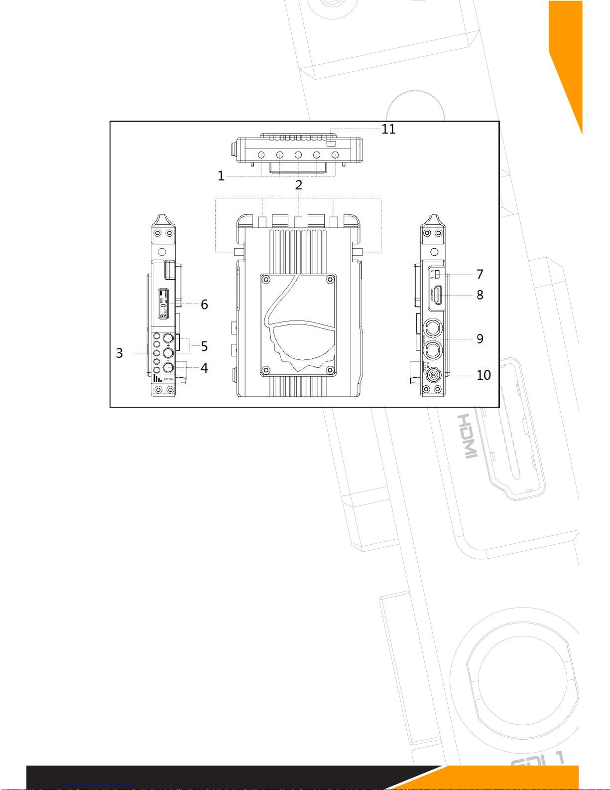
Product Description
Transmitter
1) ¼" Tripod Mount
2) Antenna Connection: SMA (male) Connector
3) Menu Button: Unlock/lock screen
4) Control Button: Press to change the channels
5) LCD Screen: Display channel, power level, temperature info, OSD states.
6) ON-OFF: Power Switch
7) SDI-IN: 3G/HD/SD-SDI Input, (BNC Female Connector)
8) SDI LOOP-OUT: 3G/HD/SD-SDI Output, (BNC Female Connector)
9) HDMI-IN: HDMI Input (Type A Female Connector)
10) DC-IN: 9 – 18V DC
11) Mini USB: For rmware upgrade use.
EN
Page 8
6
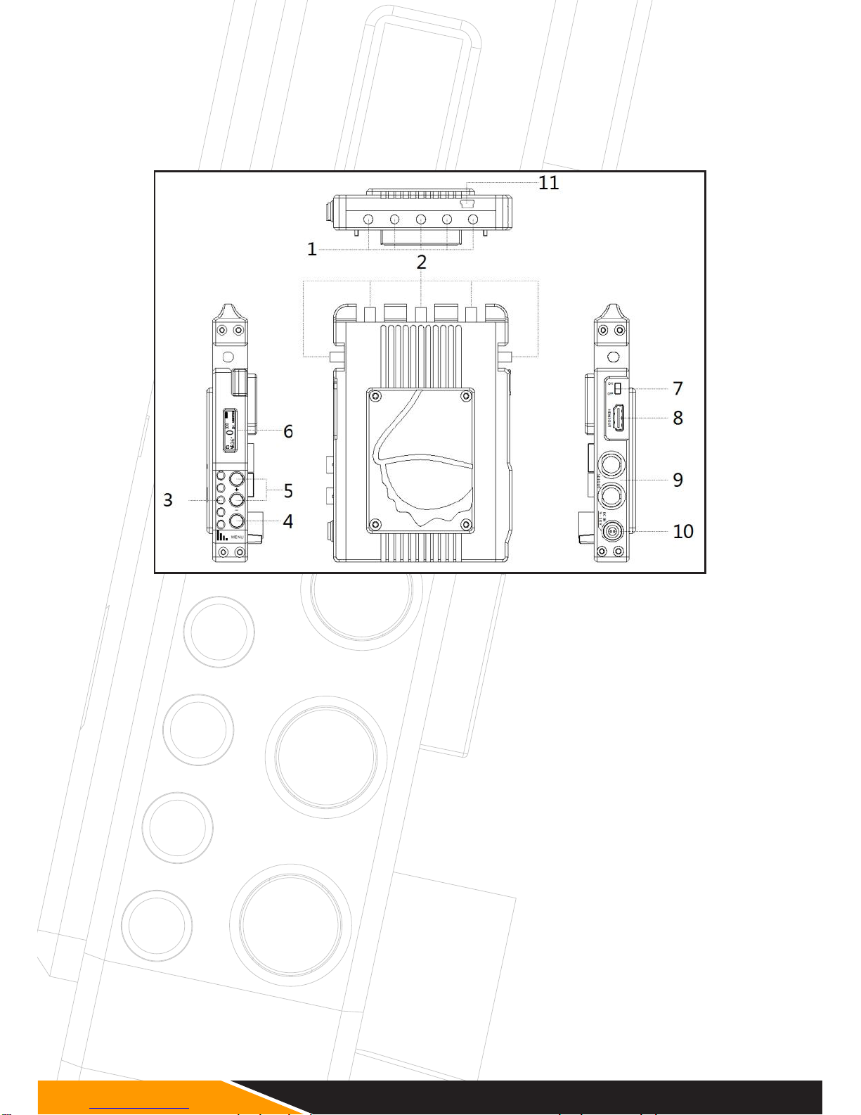
Product Description
Receiver
1) ¼" Tripod Mount
2) Antenna Connection: RP-SMA (male) Connector
3) RSSI Status Display: Signal Strength
4) Menu Button: Unlock/lock screen
5) Control Button: Press to change the channels
6) LCD Screen: Display channel, power level, temperature info, OSD state.
7) ON-OFF: Power Switch
8) HDMI-OUT: HDMI Output (Type A Female Connector)
9) Dual SDI-OUT: 3G/HD/SD-SDI Output, (BNC Female Connector)
10) DC-IN: 9.0 – 18.0V DC
11) Mini USB: For rmware upgrade
Page 9
7
Operation
Transmitter
1. Connect the two omni-directional antennas to the SMA male connectors.
2. There is a ¼" tripod mount at the base of the transmitter if required.
3. Use the enclosed 4-pin male-to-D-TAP cable to connect to a power supply
with a suitable voltage.
Receiver
1. There is a ¼" tripod mount at the base of the receiver if required.
2. Use the enclosed 4-pin male-to-D-TAP cable to connect to a power supply
with a suitable voltage.
3. Ensure you have selected the frequency that corresponds to that of the
transmitter.
Signal Distribution
Connect the camera’s SDI or HDMI output to the transmitter’s SDI or HDMI input. If
both SDI and HDMI inputs are active, the transmitter will prioritise the SDI signal.
Connect the receiver’s SDI or HDMI output to the SDI or HDMI input of the monitoring/
recording device. During active transmission, both the SDI and the HDMI output on the
receiver can be used simultaneously.
Ensure that the antennas are connected rmly, that all other connections are stable,
and that the batteries are suitable.
EN
Page 10
8
Antenna Positioning
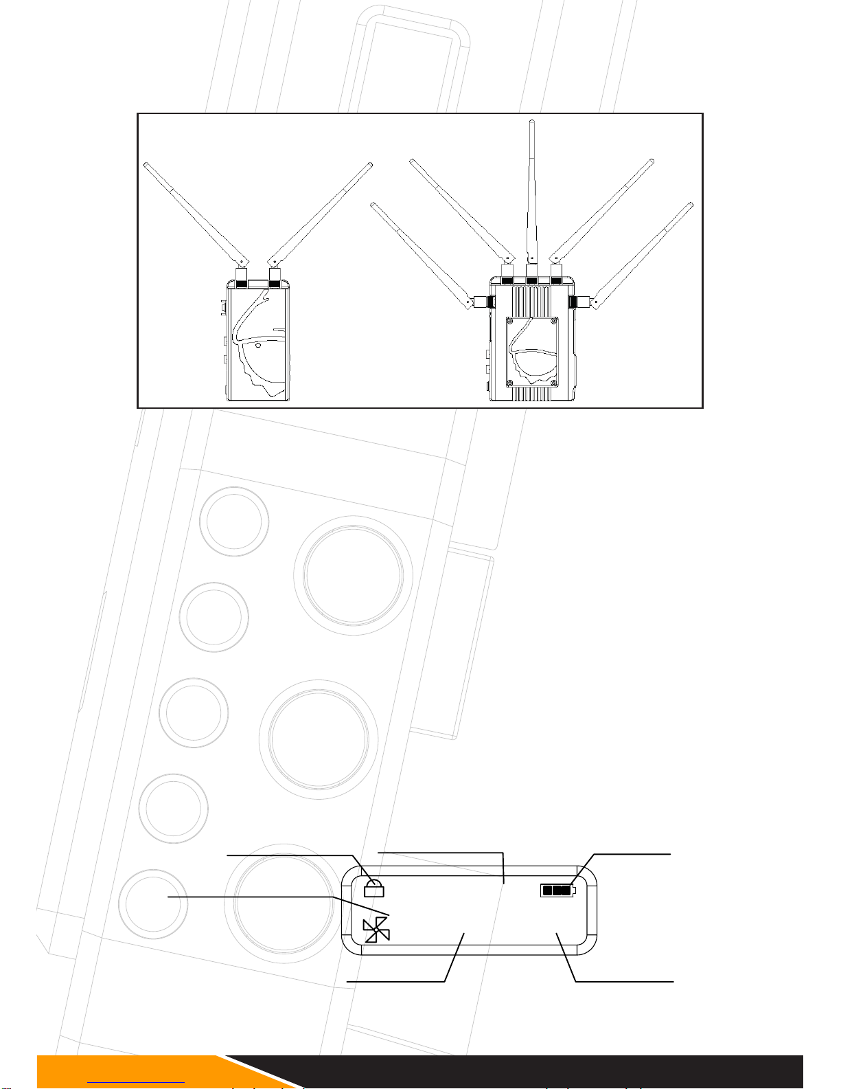
Position the antennas on transmitter and receiver as shown in the illustration. This
ensures the best possible RF performance.
Install the transmitter and the receiver as high as possible (at least 2 metres above
ground level) to maintain a good line-of-sight. During operation, try to keep the transmitter and the receiver at similar heights.
Avoid obstacles such as walls, trees, water and steel structures between transmitter
and receiver.
The connection is at its strongest when the at surfaces of the transmitter and receiver
face each other.
Functions
OLED Display
The OLED Display shows the most important information on the Transmitter and the
Receiver.
36°
0
CH
100
1080P50i
Power Info
Screen Lock/Unlock
Channel No.
Fan Status & Temperature
Video Format
Transmission Power
Page 11
9
Choosing a Channel
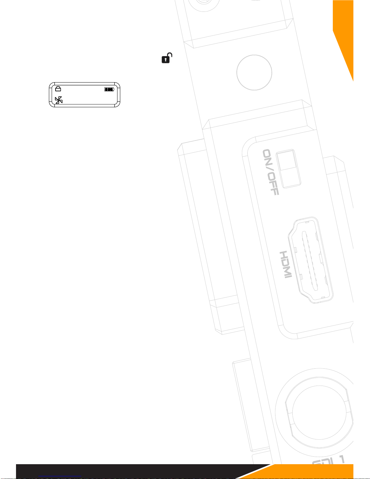
1. To choose a channel on the Transmitter press and hold the “MENU” button for 2
seconds, until unlock icon is shown” ” on the OLED.
2. Press the “+” or “-“ button to select the desired channel, then press the “MENU”
button to conrm.
1. To choose a Channel on the Receiver, press the “MENU”
button and select the channel with the “+” or “-“ button,
then press the “MENU” button to conrm.
The system functions on 10 channels in the license-free 5 GHz ISM frequency band.
Both transmitter and the receiver have a frequency selector with positions from 0-9.
The transmitter and the receiver have to be set on the same channel to work. If
several systems are used at once, then one should only use every second channel. A
maximum number of 4 systems can be used simultaneously.
DC-SCAN
The DC-SCAN is a spectrum analyzer of the 5 GHz band and shows how busy the
respective channels are. Choose a free channel for proper performance.
To enter the DC-SCAN, press the ”-” button for 3 seconds. The frequency scanner is
only available on your HDMI output. To switch the DC-SCAN off press the ”-” button
again for three seconds.
Channel 0 in the DC-Scan mode displays the antenna function monitor. If the
antenna green everything is ne. If it is red there is a problem with the antennas.
OSD
The OSD is important when you congure your device or if you need status information. In live situations the OSD might be annoying. The OSD can therefore be switched
off on the receiver. To switch it off, please press the ”MENU” button three times, and
then press the “+“ button, conrm it by pressing the ”MENU” button agin. A indicator
on the OLED display of the receiver shows you the OSD state. To switch it on again,
press the ”MENU” button three times, and than press the “+“ button, conrm it by
pressing the ”MENU” button again and check the state on the OLED display of the
receiver.
Reducing Transmission Power
To reduce the transmitting power, press the transmitter and “+” or “-” buttons at the
same time.
36°
0
CH
100
1080P50i
EN
Page 12
10
Fan Control
The fan control allows the user to reduce the volume of the fan during audio recording.
To switch the fan on the receiver off or on, press the “MENU” button twice. Press the
“+” button, then conrm selection with the “MENU button. A indicator on the OLED
display of the receiver shows you the fan state.
On the transmitter press the “+“ button and the “-“ button together for 3 seconds
until the OLED display shows the fan menu. To switch the fan ON press the “+“ but-
ton, to switch it OFF press the “-“ button and conrm your selection with the “MENU“
button.
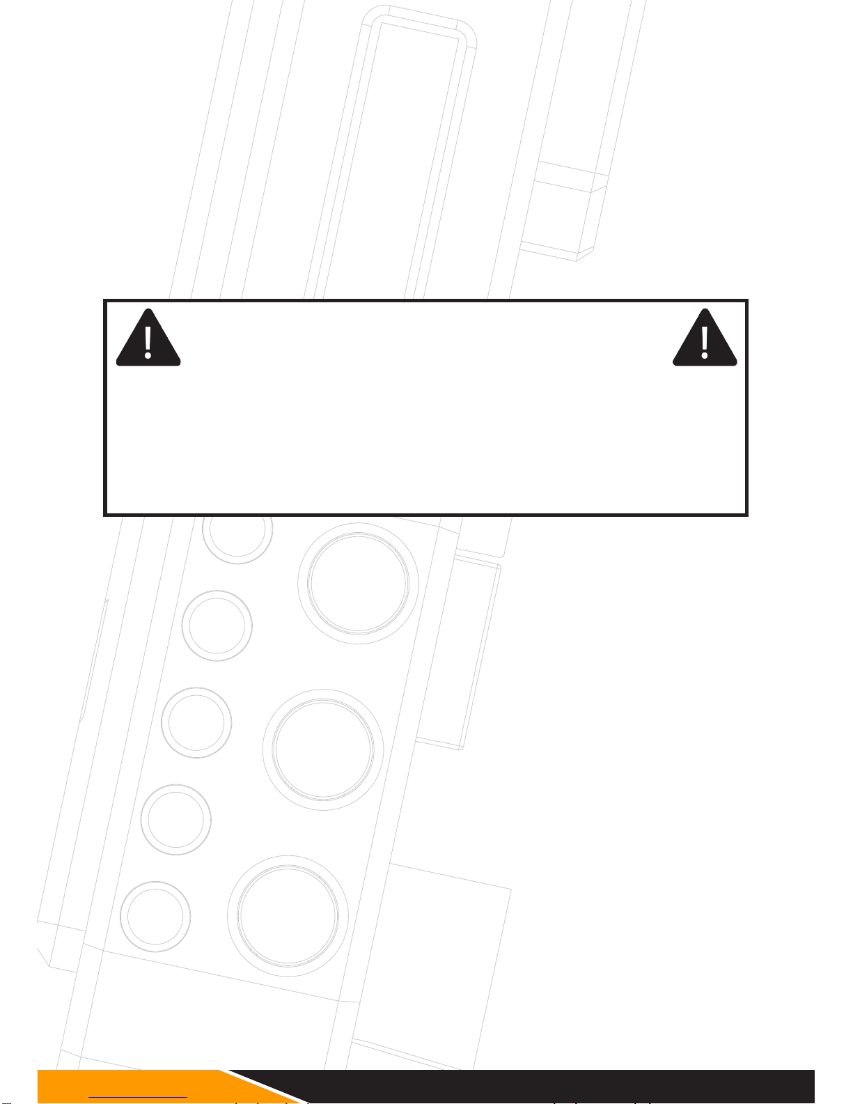
Warning!
Switching off the fans may be required in some situations, but doing this
permanently is not recommended. This will effect the life-time of your
wireless equipment. To prevent your device from damage, fans switch on
automatically after a reboot. If the temperature exceeds 75 degrees
Celcius, please switch on the fans instantly. Any damage caused by
over-heating voids warranty.
Cinema Mode
The cinema mode is an automatic mode that only works via SDI signal. The fan is
switched off at the start of recording via the record trigger of the camera. When the
recording is nished the fan starts automatically.
Page 13
11
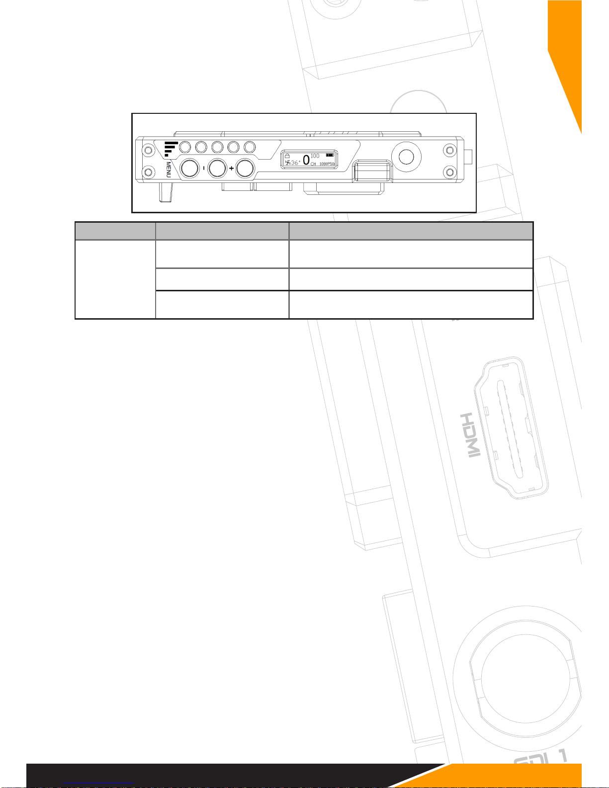
Display Status Description
RSSI 0-1 LEDs
Radio signal strength is weak and artefacts are visible in
the video signal
2-3 LEDs Radio signal strength is normal and video quality is good
4-5 LEDs
Radio signal strength is very strong and video quality is
very good
RSSI Display
The RSSI (Received Signal Strength Indicator) display shows the strength of the signal,
allowing the operator to ensure the system is working property.
Establishing a Connection
Once all previous steps have been performed, turn on the transmitter and the receiver
using the power switch.
Once the transmitter recognizes a video input, the video format will be displayed on
the LCD screen.
It takes between 10-30 seconds for the transmitter to connect to the receiver. During
this brief period, the receiver’s video out displays “Waiting for connection”.
EN
Page 14
12
Maintenance
Please do not attempt to repair, modify or alter these devices under any circumstances.
Clean the devices with a soft, clean, dry and lint-free cloth. Do not open the devices,
they contain no user-serviceable parts.
Storage
The devices can be stored at temperatures between -20°C and 60°C. For long-term
storage, please use the original transport case and avoid environmental conditions
such as high humidity, dust, or excessively acidic or base surroundings.
Warning!
To ensure your own safety, please use only high-quality brand name
batteries, and follow the safety instructions provided by the manufacturer.
Troubleshooting
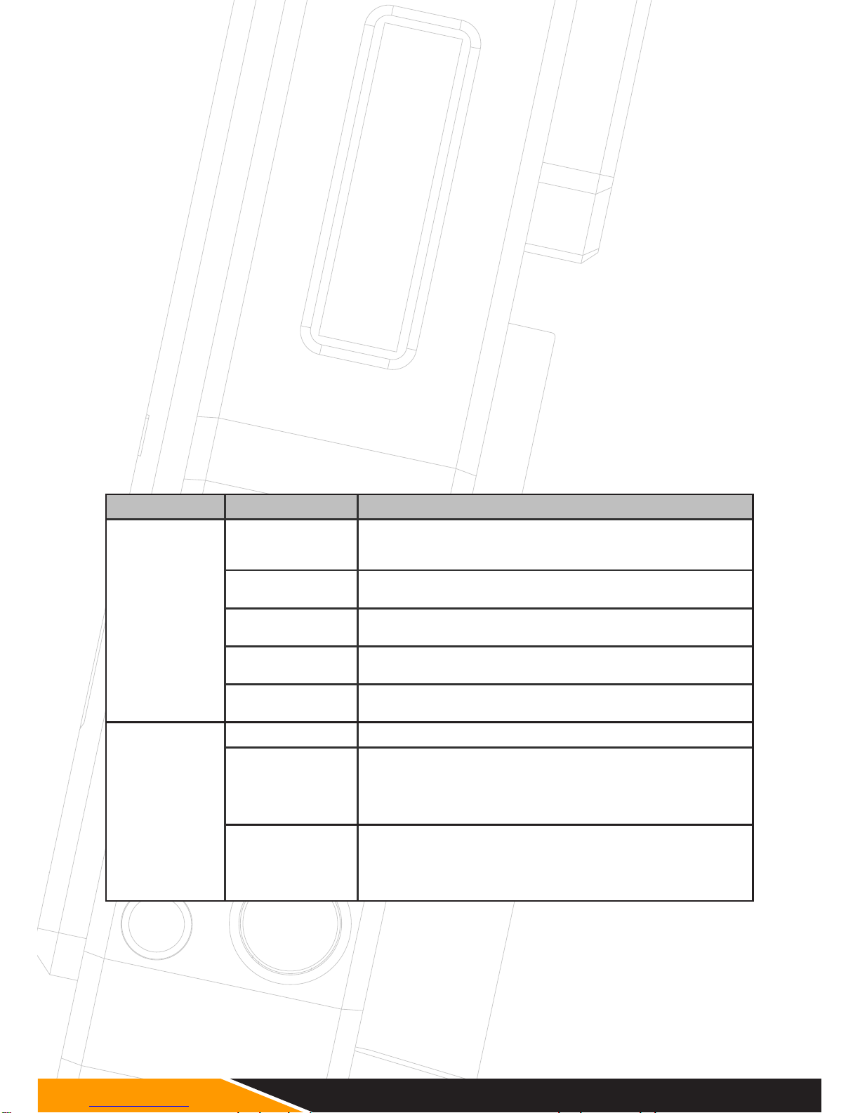
Possible Cause Possible Solution
No video output
Lack of power
Check power supplies of transmitter and receiver and ensure
that all cables are connected properly and that there is sufcient
power.
Antennas
Ensure antennas are not damaged and are rmly connected.
Please use the DC-Scan to check.
Video connection
cable
Examine the transmitter’s “Video” LED display. If the LED is dark,
check the HDMI or SDI connection cable.
Frequency selection
Ensure that the transmitter and receiver are set to the same
channel.
Unsupported video
format
Make sure you using a supported video format.
Inadequatevideo
quality
Connections Ensure that all SDI or HDMI cables are rmly connected.
Range is too
great or signal is
obstructed
Check how many “RSSI” LEDs are lit on the receiver. For decent
quality, at least 2-3 LEDS should be lit. If only one is lit, the
signal is weak and the distance between transmitter and receiver
should be reduced. Alternatively, obstacles between the devices
should be removed or another channel selected.
Radio signal is
experiencing
interference
Open the DC-Scan and choose a free channel.
Page 15
13
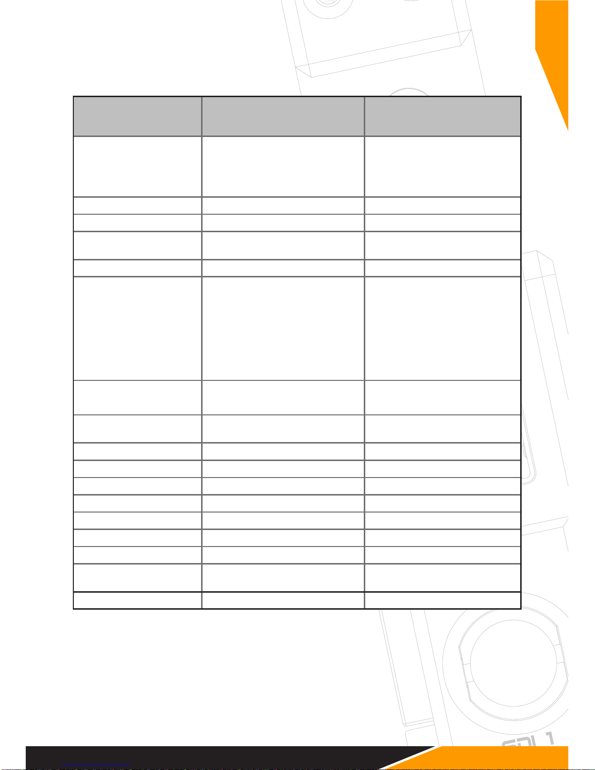
Technical Specications
Transmitter Receiver
Connections
1x SDI Input (BNC female)
1x SDI Output (BNC female)1x HDMI
Input (Type A female)
2x Antenna (RP-SMA male)
1x DC Input (4-pin female)
2x SDI Output (BNC female)
1x HDMI Output (Type A female)
5x Antenna (RP-SMA male)
1x DC Input (4-pin female)
Power 9.0 – 18.0V DC 9.0 – 18.0V DC
Power Consumption < 8 W < 8 W
Dimensions (LxBxH), w/o
Antennas
143.5 x 74.5 x 21.4mm 147.8 x 100 x 20mm
Weight 380g 540g
Supported Video Formats 1080p(60, 59.94, 50, 30, 1080p(60, 59.94, 50, 30,
29.97, 25, 24, 23.98) 29.97, 25, 24, 23.98)
1080i (60, 59.94, 50) 1080i (60, 59.94, 50)
720p (60, 59.94, 50) 720p (60, 59.94, 50)
576i (50) 576i (50)
480i (59,94) 480i (59,94)
Audio Format SDI Embedded 2 Channel SDI Embedded 2 Channel
Audio 24bit/48kHz Audio 24bit/48kHz
Displays 0.91 inch OLED panel
0.91 inch OLED panel, 5 LEDs for
RSSI indicator
Frequencies 5190, 5230, 5755 and 5795MHz 5190, 5230, 5755 and 5795MHz
Transmitting Power Less than 20 dBm -
Receiver Sensitivity - - 75 dBm
Bandwidth 40MHz 40MHz
Modulation mode 5G WIFI:OFDM 5G WIFI:OFDM
Max. of Transmit power 5G WIFI: 21.96dBm 5G WIFI: 21.96dBm
Maximum Antenna Gain 5G WIFI : 3.3dBi 5G WIFI : 3.3dBi
Operating Temperature
0 – 40°C (Operation) -20 – 60°C
(Storage)
0 – 40°C (Operation) -20 – 60°C
(Storage )
Certication CE CE
EN
Page 16
14
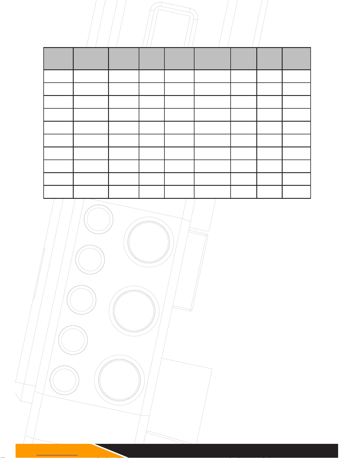
Country-specic operating license
Position
(Kanal)
Frequenz Europa USA Canada Russland Japan China Turkei
0 5550 MHz x x x
✓
x x x
1 5590 MHz x x x
✓
x x x
2 5630 MHz x x x
✓
x x x
3 5670 MHz x x x
✓
x x x
4 5150 MHz x x x
✓
x x x
5 5190 MHz Indoor Indoor Indoor
✓
Indoor
✓
Indoor
6 5230 MHz Indoor Indoor Indoor
✓
Indoor
✓
Indoor
7 5270 MHz x x x
✓
x x Indoor
8 5310 MHz x x x
✓
x x Indoor
9 5510 MHz x x x
✓
x x x
Before operating the radio system, please check the frequency regulations in the
respective country.
Included Accessories
1x Transmitter
1x Receiver
9x External Antennas (can be ordered seperately)
2x DC Adapter cables from Anton Bauer (D-Tap) (m) to 4-pin DC connector(m)
2x Power supplies
1x Magic-arm with 1/4" Screw
1x Hot-shoe adapter
1x Quickstart Guide
Page 17
15
Notes
EN
Page 18
Errors and omissions excepted.
 Loading...