

Page 1
V
V
V
P
P
P
-
-
-
6
6
6
0
0
0
2
2
2
H
H
H
H
H
H
T
T
T
U
U
U
0
User Manual
Presentation Switcher
with HDMI and VGA solutions
6x2
VP-602HHTU
V.2015VP-602HHTU.00
Page 2

V
V
V
P
P
P
-
-
-
6
6
6
0
0
0
2
2
2
H
H
H
H
H
H
T
T
T
U
U
U
1
COPYRIGHT AND TRADEMARKS
All rights reserved by © DVTECH Solution Corp. No part of this document may be
reproduced in any form or by any means without written permission from the product
manufacturer. Changes are periodically made to the information in this document.
They will be incorporated in subsequent editions. The product manufacturer may make
improvements and / or changes in the product described in this document at any time.
All the registered trademarks referred to this manual are belonging to their respective
companies.
Page 3

V
V
V
P
P
P
-
-
-
6
6
6
0
0
0
2
2
2
H
H
H
H
H
H
T
T
T
U
U
U
2
BEFORE YOU BEGIN
Follow all instructions marked on the device during using.
Provide proper ventilation and air circulation and do not use near water.
It is better to keep it in a dry environment.
Place the device on a stable surface (example cart, stand, table, etc.).
The system should be installed indoor only. Install either on a sturdy rack or desk in a
well-ventilated place.
Make sure the rack is level and stable before extending a device from the rack.
Make sure all equipments installed on the rack including power strips and other
electrical connectors are properly grounded.
Only use the power cord supported with the device.
Do not use liquid or aerosol cleaners to clean the device.
Always unplug the power to the device before cleaning.
Unplug the power cord during lightning or after a prolonged period of non-use to avoid
damage to the equipment.
Do not stand on any device while installing the device to the rack.
Do not attempt to maintain the device by yourself, any faults, please contact your
vendor.
Save this manual properly for future reference.
Page 4

V
V
V
P
P
P
-
-
-
6
6
6
0
0
0
2
2
2
H
H
H
H
H
H
T
T
T
U
U
U
3
TABLE OF CONTENTS
Copyright and Trademarks .......................................................................................................... 1
Before You Begin .......................................................................................................................... 2
Table of Contents .......................................................................................................................... 3
Chapter 1 Switcher System Overview ....................................................................................... 5
1.1 Introduction ..................................................................................................................... 5
1.2 Packing ............................................................................................................................ 6
Chapter 2 Features ...................................................................................................................... 7
Chapter 3 Specifications .............................................................................................................. 8
Chapter 4 Device Installation ...................................................................................................... 9
Chapter 5 Front/Rear Panels .................................................................................................... 10
5.1 Front Panel.................................................................................................................... 10
5.2 Rear Panel .................................................................................................................... 12
Chapter 6 Connections .............................................................................................................. 15
6.1 Input Connections ........................................................................................................ 15
6.2 Output Connections ..................................................................................................... 16
6.3 Multiple Connections ................................................................................................... 16
6.4 Remote Control Connection ....................................................................................... 17
6.5 IR Pass-Through Connection ..................................................................................... 18
6.5.1 Normal IR Connection...................................................................................... 18
6.5.2 Extended IR Connection.................................................................................. 19
6.6 Power Connection........................................................................................................ 19
6.7 Ports and Switchers ..................................................................................................... 20
6.7.1 RS-232 ............................................................................................................... 20
6.7.2 HDBaseT Output Port ...................................................................................... 22
6.7.3 Output LED ........................................................................................................ 22
6.7.4 Output Cable ..................................................................................................... 23
6.7.5 DIP Switcher for 3 Pins .................................................................................... 24
Chapter 7 Remote Configurations ........................................................................................... 25
7.1 Telnet Commands ........................................................................................................ 25
7.1.1 Command List and Reboot ............................................................................. 25
7.1.2 IP/Telnet Configuration .................................................................................... 26
7.1.3 Device Configuration ........................................................................................ 28
7.1.4 AV Matrix Protocol Command ......................................................................... 35
7.2 RS-232 Commands ..................................................................................................... 36
7.2.1 Commands List and Status ............................................................................. 37
7.2.2 HDMI Command ............................................................................................... 38
Page 5

V
V
V
P
P
P
-
-
-
6
6
6
0
0
0
2
2
2
H
H
H
H
H
H
T
T
T
U
U
U
4
7.2.3 EDID Command ................................................................................................ 39
7.2.4 Audio Commands ............................................................................................. 39
7.2.5 Restore Default Command.............................................................................. 41
Chapter 8 Troubleshooting ........................................................................................................ 42
Appendix A HDBaseT Firmware Upgrade .............................................................................. 44
VE-70HHTW-F HDBaseT F/W Upgrade ......................................................................... 44
Switcher HDBaseT F/W Upgrade .................................................................................... 46
Appendix B Extender ................................................................................................................. 49
Features ............................................................................................................................... 50
Specifications ...................................................................................................................... 51
IR Receiver Cable Directions............................................................................................ 52
IR Blaster Cable Directions ............................................................................................... 52
HDMI Output Connector .................................................................................................... 52
Wiring Information for Link Connector ............................................................................. 53
Appendix C Firmware Upgrade ................................................................................................ 54
Matrix .................................................................................................................................... 54
F/W Upgrade ....................................................................................................................... 55
General Upgrade ........................................................................................................ 55
Module Upgrade ......................................................................................................... 56
Manual Upgrade ......................................................................................................... 58
Network ................................................................................................................................ 60
IPM Upgrade ....................................................................................................................... 61
Page 6
V
V
V
P
P
P
-
-
-
6
6
6
0
0
0
2
2
2
H
H
H
H
H
H
T
T
T
U
U
U
5
CHAPTER 1 SWITCHER SYSTEM OVERVIEW
1.1 Introduction
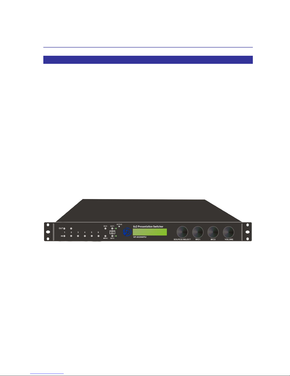
The Presentation Switcher is a high performance, zero-second latency switching
equipment with 6x2 transmission interfaces. It is a switcher and also a converter means
that it can handle virtually video/audio signals on its 6 inputs including HDMI and VGA.
Split the HDMI signal and mix with the audio signal comes from the MIC1/2 input
interface integrated the optical SPDIF or R/L stereo audio output signal. The built-in
converter handles analog to digital conversion, as well as the signals conversion is
virtually converted to any output equipments including any projector, TV or other audio
amplifier. Built-in extender interfaces allowing you to integrate external extensible
accessory devices to transmit data or to over long distances up to 70 meters.
The Switcher can be controlled in some ways; the front panel offers input/output
selection and audio configured control, as well as an IR receiver connected to rear panel
for user to control the VP-602HHTU with a IR controller. The Switcher provides the utilize
TCP/IP and RS232 rear panel allowing users to control the switcher through a browser
on the PC.
Figure 1-1 VP-602HHTU Switcher
Page 7
V
V
V
P
P
P
-
-
-
6
6
6
0
0
0
2
2
2
H
H
H
H
H
H
T
T
T
U
U
U
6
1.2 Packing
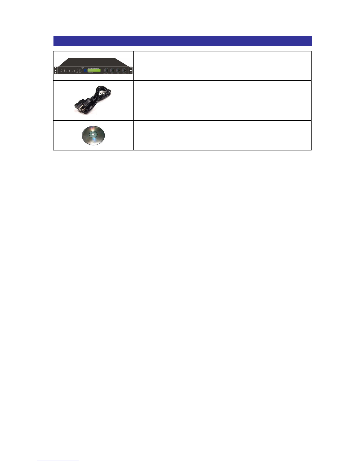
VP-602HHTU Switcher *1
Power Cord *1
CD *1
Page 8

V
V
V
P
P
P
-
-
-
6
6
6
0
0
0
2
2
2
H
H
H
H
H
H
T
T
T
U
U
U
7
CHAPTER 2 FEATURES
3*HDMI In (Up to 4K*2K@30fps or YC
B CR
4:2:0 4K*2K@60fps)
3*VGA In + 3*3.5 Stereo Audio Inputs Associated with Each VGA Connection
(VGA Support Resolution Shown Below)
VGA Input (Support Video Modes)
60Hz
640*480, 800*600, 1024*768, 1152*864, 1280*600, 1280*720,
1280*768, 1280*800, 1280*960, 1280*1024, 1360*768, 1366*768,
1400*1050, 1440*900, 1600*900, 1600*1200, 1680*1050, 1920*1080
75Hz
640*480, 800*600, 1024*768, 1152*864, 1280*800, 1280*1024
2*Microphone Input (XLR Connector)
MIC inputs can be provided up to +48V phantom power
2*HDMI Output (Different Displays) w/HDBaseT 70 Meters Output (Bypass Input
Audio Only, None Microphone Mixer)
Knob Adjustable for Source Volume, Microphone 1&2 Volume, Main Audio OUT
Volume. (Press Knob Once for Mute)
Microphone “Take-Over” Mode to Mix the Microphone Signal w/ the Source Audio
Independent L/R Output, Coaxial Output, and TOSTLINK SPDIF Output (Source
Audio is from 3.5 Stereo Audio or De-embed from HDMI Source)
Support EDID Management
LCD Display for Status Read Easily
8*Front Panel Pushbuttons for Source Selection (Output *2/Input *6)
Supports IR Remote/RS-232/Ethernet Control
HDBaseT Technology, Use One CATx Cable to Install Easily
Internal universal power supply
1U rack Unit Height
Page 9

V
V
V
P
P
P
-
-
-
6
6
6
0
0
0
2
2
2
H
H
H
H
H
H
T
T
T
U
U
U
8
CHAPTER 3 SPECIFICATIONS
Hardware
LCD Module
1
Pushbuttons
12
Knob
4
Input Connector
HDMI Type A*3/VGA*3
Output Connector
HDMI Type A*2 /RJ-45*2
IR IN
3.5 Phone Jack*2
IR OUT
3.5 Phone Jack*2
RS-232
3.5 Phone Jack*2
MIC Input
XLR Connector*2
Audio Input
3.5 Phone Jack*3
Audio Output
RCA Connector (R,L)*2 sets
Digital Optical Toslink*2
RCA Digital Audio*2
LAN Connector
RJ-45*1
IR Ext.
1
3 pins Dip Switcher
1
Power
100VAC~240VAC, 50/60Hz, internal
Main Power Switch
1
Housing
Aluminum/Metal
Mounting
1U Rack mountable
Weight
3.6 kg
Dimensions (LxWxH)
482*357*45 mm
Control Information
HDMI Cable Distance
10 meters (At least)
Cat.5e Cable Distance
70 Meters (Max.)
Baud Rate
9600 bps, 8 data bits, 1 stop bit, no parity
Ethernet Protocol
HTTP, DHCP, TCP/IP, Telnet
Serial Control Port
RS-232: 9 Pin Female D Type Connector
Remote Control
Remote Controller, IR Receiver Cable
Telnet Server
LAN
Page 10
V
V
V
P
P
P
-
-
-
6
6
6
0
0
0
2
2
2
H
H
H
H
H
H
T
T
T
U
U
U
9
CHAPTER 4 DEVICE INSTALLATION
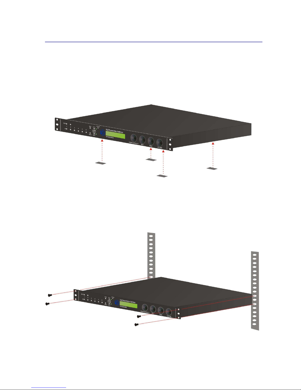
The Switcher has a black metallic housing. It can be placed on a sturdy desk directly or
installed on a rack.
Attach the rubber feet to the bottom of Switcher, Place the Switcher on a sturdy, level
surface that can support Switcher’s weight.
Figure 4-1 Place the Switcher on a sturdy surface
Or use the screws provided with the rack and a screw driver to firmly tighten the Switcher
in the rack to prevent working lose due to vibration in the rack.
Figure 4-2 Mount the Switcher in the rack
Page 11
V
V
V
P
P
P
-
-
-
6
6
6
0
0
0
2
2
2
H
H
H
H
H
H
T
T
T
U
U
U
10
CHAPTER 5 FRONT/REAR PANELS
5.1 Front Panel
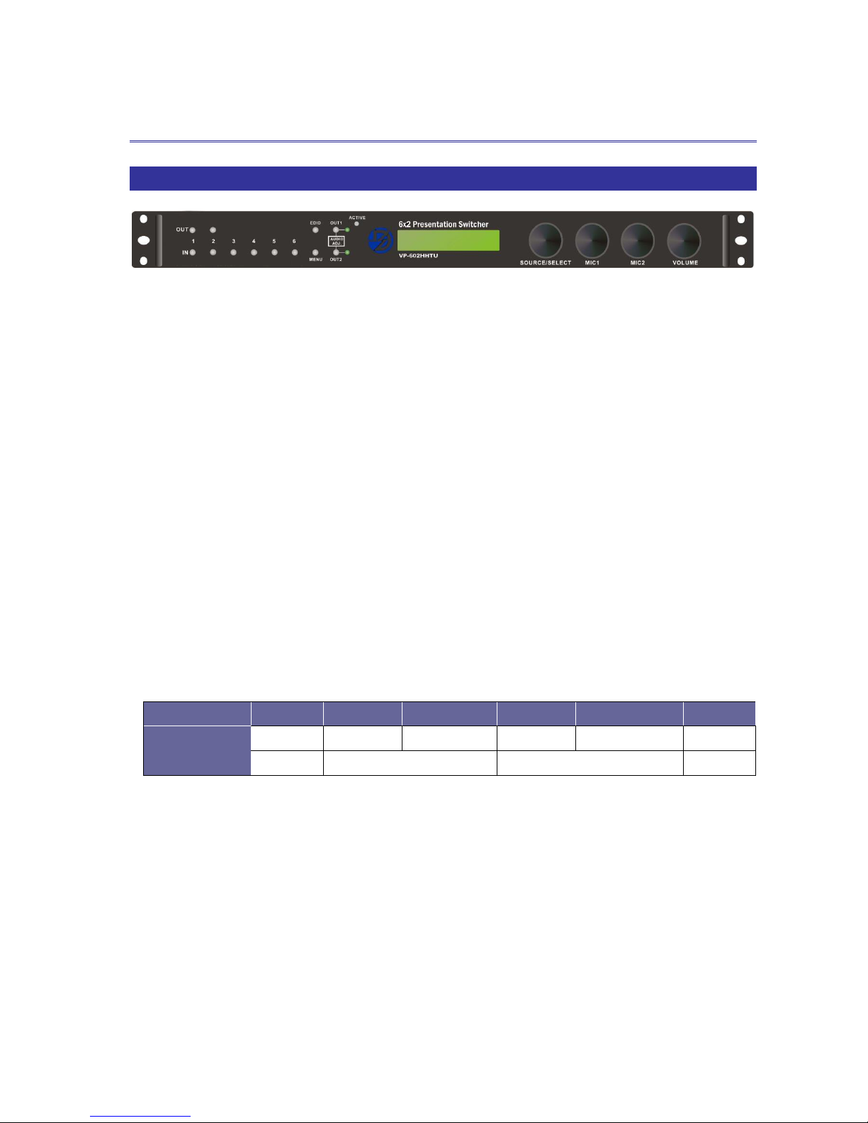
Figure 5-1 VP-602HHTU Switcher Front Panel
The Switcher supports up to 8 switching keys (Input*6/Output*2) on the Front Panel.
These keys allow you to configure the connected signal quickly and indicate the
connection status clearly showing on the LCD display.
OUT1~2 keys (output channel): Specifies the channel 1 and 2 for HDMI/HDBT/AUDIO
signal output. You can use these keys to switch output channels.
IN1~6 keys (input channel): Specifies the one of input channels that comes from HDMI
1~3 or VGA4~6 + AUD4~6 interface to output. These keys configure the signal sources
of channel1~6. You can also use these keys to switch input channels.
EDID: This feature provides you to get the best information for the best video and
audio results come from input channels. And all of them will be held automatically
within your switcher. Enabling your switcher to transfer the signals to your output
channels so that ensuring the best compatibility and best video/audio results. EDID
Value: 108P, OUT1, OUT2, 01R, 02R, 720P
EDID Value
0 1 2 3 4
5
Description
108P
OUT1
OUT2
01R
02R
720P
Default
Local Output (HDMI)
Remote Output (HDBT)
Default
MENU: Press this key to switch the configuration status showing on the LCD display.
OUT1 and OUT2: Switch the output volume of adjustable audio set – AUD OUT 1 or
AUD OUT 2 on the rear panel connection.
ACTIVE: A clear LED indicator designed for reaction by pressing keys on the front
panel.
LCD: LCD display shows current switcher status and operation status. Press Menu key
to switch the LCD display screen. When idling on the same screen for about 5 seconds,
the system will return to main screen.
Page 12
V
V
V
P
P
P
-
-
-
6
6
6
0
0
0
2
2
2
H
H
H
H
H
H
T
T
T
U
U
U
11
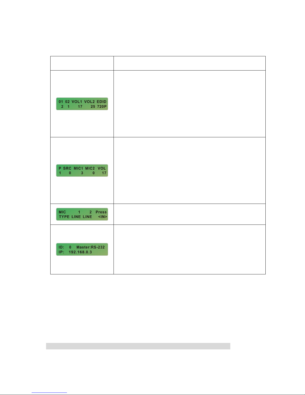
LCD Display
Description
* HDMI Output Channel 01: Specify the signal comes from
Input Channel 2.
* HDMI Output Channel 02: Specify the signal comes from
Input Channel 1.
* VOL1 and VOL2: Specify the sound output for AUD OUT 1
and 2 are level 17 and 25.
* EDID Value: 720P (Default Value)
* P: Show you currently AUD OUT configuration is 1 or 2.
* SRC: Specify the sound volume comes from connected
input port (HDMI1~3 or VGA4~6). Value 0 means mute.
* MIC 1 and MIC2: Specify the MIC1 and MIC2 volume are
level 3 and 0.
* VOL: Total output volume, namely the sound volume of
mixed SRC, MIC1 and MIC2.
Specify you the types of microphones are LINE in or 48V
phantom power.
* ID: Specify the Switcher Static ID to 0.
* Master: Specify the remote control interface is RS-232 or
Line.
* IP: Show the Switcher IP address (Default Value:
192.168.0.3)
SOURCE/SELECT knob: Adjusts the output volume, press the knob once to mute the
output and press again to restore the volume.
MIC1/MIC2 knobs: Adjusts the MIC1/MIC2 volume, press the knobs once to mute the
MIC1/MIC2 and press again to restore the volume.
VOLUME knob: Adjusts the mixed audio volume, press the knobs once to mute the
mixed audio and press again to restore the volume.
You can adjust the volume level from value 0 (mute) to value 30 (max.).
Page 13
V
V
V
P
P
P
-
-
-
6
6
6
0
0
0
2
2
2
H
H
H
H
H
H
T
T
T
U
U
U
12
5.2 Rear Panel
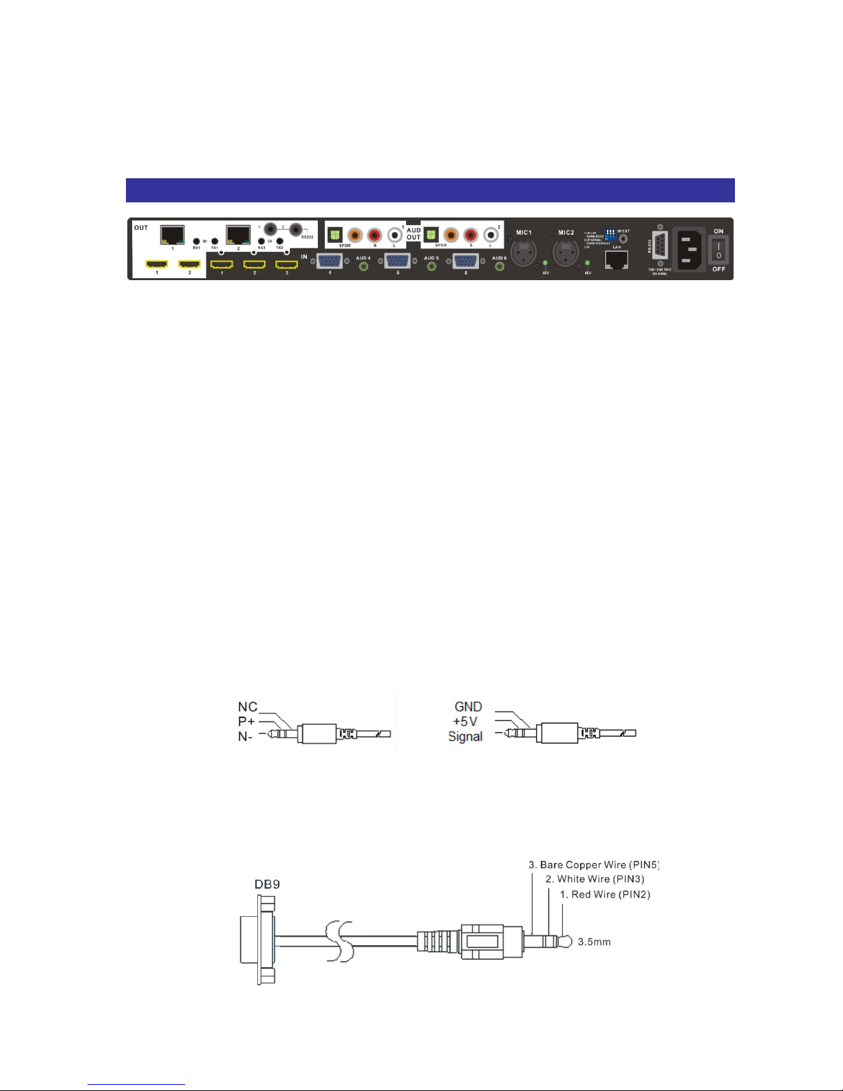
Figure 5-6 VP-602HHTU Switcher Rear Panel
The Switcher supports up to 6 input jacks (HDMI x 3 VGA+Audio set x 3), MIC input
port*2 and multiple output interfaces on the rear panel. The input interfaces allowing you
to connect to different equipments including CD/DVD players, Blue Ray player, PS3,
Video Camera, STB and so on. The HDMI output can be connected to projectors, video
recorders, multiplexers and other displayers directly. Other output interfaces allowing
you to connect to extensible accessory devices for over long connections with terminal
display devices.
OUT1~2 (HDMI): The Switcher Output connector is connected to the A/V, HDTVs or
other output devices directly.
OUT1~2 (RJ45): The Switcher Output connector is connected to the A/V, HDTVs or
other output devices via an extensible accessory device for over long connection.
IR (RX1/RX2,TX1/TX2): Through a IR Blaster/Receiver cable connection, you can
extend the IR signals transmission between Switcher and Remote devices.
IR Blaster Pin Definitions IR Receiver Pin Definitions
RS232 1~2 ports: Through a 3.5mm to DB9 female RS232 cable for a long-distance
serial data transmission.
PIN5
PIN3
PIN2
Page 14
V
V
V
P
P
P
-
-
-
6
6
6
0
0
0
2
2
2
H
H
H
H
H
H
T
T
T
U
U
U
13
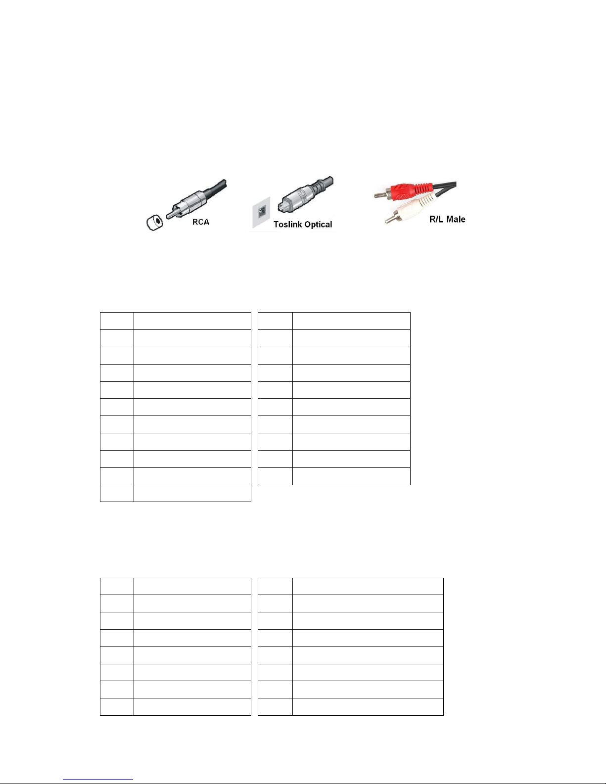
AUD OUT 1~2 sets: These ports are complied with SPDIF and R/L audio connecters
that are connected to the audio output device.
- SPDIF ports: The Switcher supports the signal transmitted over either a coaxial
cable with RCA connectors or a fiber optic cable with Toslink connectors to keep the
signal transmission fidelity in a short-distance.
- R/L ports: The Switcher supports the stereo R/L analog audio output interface.
IN1~3 (HDMI): These ports receive the HDMI signals through a HDMI cable comes
from the input sources.
HDMI Type A Connector host assignment:
Pin #
Signal
Pin #
Signal
1
TMDS Data2+
11
TMDS Clock Shield
2
TMDS Data2 Shield
12
TMDS Clock-
3
TMDS Data2-
13
NC 4 TMDS Data1+
14
NC 5 TMDS Data1 Shield
15
DDC-SCL
6
TMDS Data1-
16
DDC-SDA
7
TMDS Data0+
17
DDC-Ground
8
TMDS Data0 Shield
18
+5V Power
9
TMDS Data0-
19
Hot Plug Detect
10
TMDS Clock+
IN4~6 (VGA+Audio): These ports receive the VGA and Audio signals through VGA
and Audio cables come from the input sources.
VGA Connector assignment:
Pin #
Signal
Pin #
Signal
1
Red 9
NC 2 Green
10
Sync return
3
Blue
11
NC 4 NC 12
Bi-directional data (SDA)
5
Return (GND)
13
Horizontal sync
6
Red return
14
Vertical sync
7
Green return
15
Data clock (SCL)
Page 15

V
V
V
P
P
P
-
-
-
6
6
6
0
0
0
2
2
2
H
H
H
H
H
H
T
T
T
U
U
U
14
8
Blue return
MIC1, 2: The Switcher supports at least 2 microphones connection.
48V LED: The Switcher supports the microphone with 48V phantom power. When you
want to connect a 48V Condenser microphone, you can press the MENU key on the
front panel to switch the LCD screen to microphone configuration screen, then press IN
key 1 or 2 to select microphone input port 1 or 2 for a 48V phantom power. Once the
connection is successful, the 48V LED indicator turns to solid green.
When using a 48V microphone (phantom power), make sure the MIC connector on
the rear panel of your Switcher is connected to a 48V microphone in order to avoid
the damage to non-48V type of microphone.
Switcher: The switcher supports 3 pins DIP for connected configurations.
- Pin 1: RS232/LAN
- Pin 2: IP RESET
- Pin 3: NC
IR EXT: This is used for connecting the IR Receiver. Refer to 6.5 IR Pass-Through
Connection.
LAN Port: Use the RJ-45 connection cable to connect the Internet and the Switcher.
The entire PC at the same network can control the Switcher through the LAN port.
Refer to 6.4 Remote Control Connection
RS-232 connector: Uses a 9-pin RS-232 cable to connect both computer serial port
(for example: COM1 or COM2) and the Switcher’s RS-232 communication connector,
refer to 6.7.1 RS-232. The computer can then be deployed to control the Switcher
through a terminal session (command line) on your control PC. Refer to
Chapter 7 Remote
Configurations
for more information.
Power port: The Power Port is applicable for 100~240VAC, 50~60Hz connected to the
outlet of power source. Refer to 6.6 Power Connection.
Power Switch: To switch power ON or OFF the Switcher.
Page 16
V
V
V
P
P
P
-
-
-
6
6
6
0
0
0
2
2
2
H
H
H
H
H
H
T
T
T
U
U
U
15
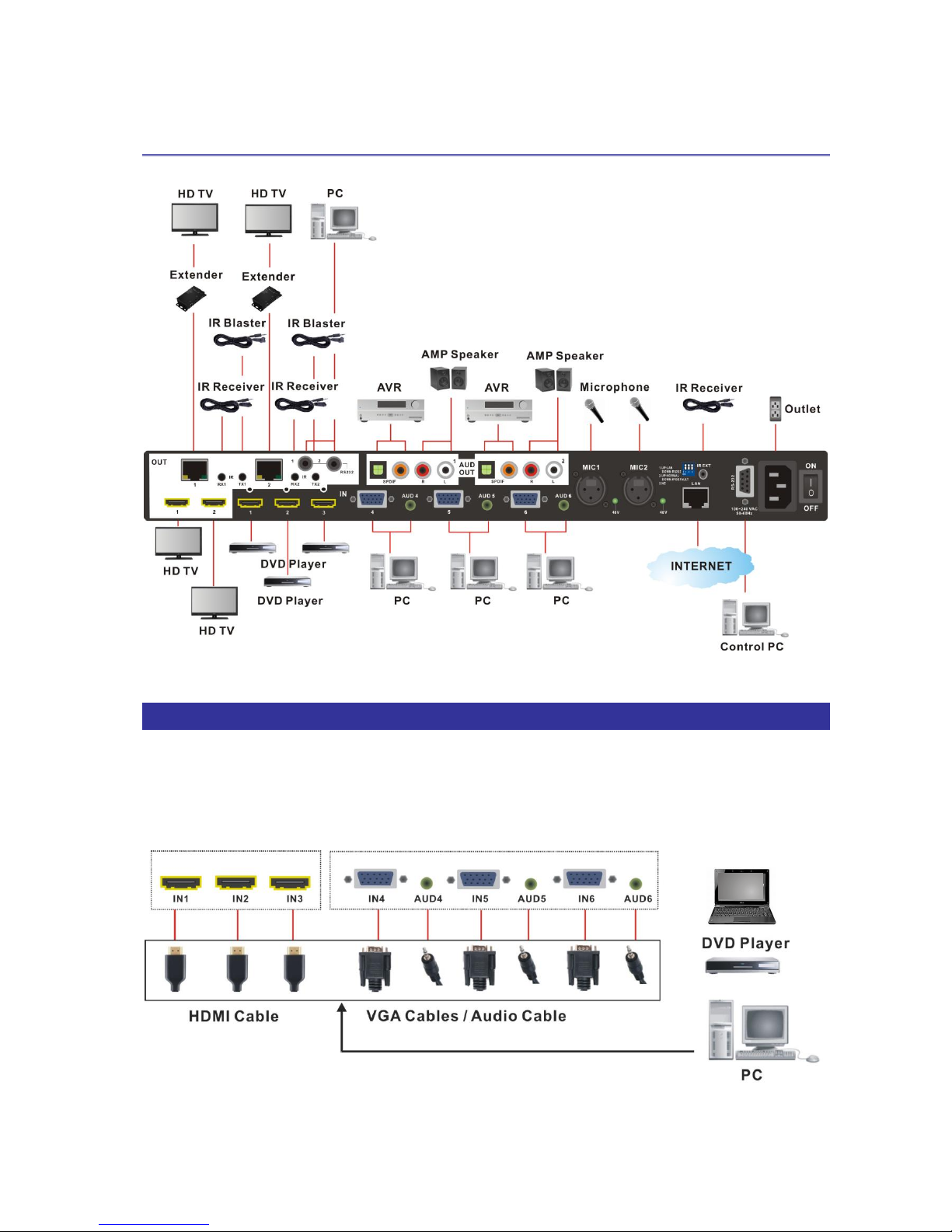
CHAPTER 6 CONNECTIONS
Figure 6-1 Switcher Connections
6.1 Input Connections
Use the HDMI/VGA+Audio connecting cable to connect the Input serial jack (IN1~3/
IN4~6) to the output source jack of the Blu-ray/DVD player displays/graphics
workstations/PC.
Notebook
Figure 6-2 Input Connections
Page 17
V
V
V
P
P
P
-
-
-
6
6
6
0
0
0
2
2
2
H
H
H
H
H
H
T
T
T
U
U
U
16
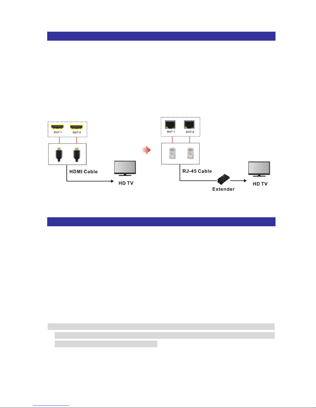
6.2 Output Connections
- Use the HDMI cable to connect the output jack (OUT1 ~ OUT2 with HDMI interface)
on the rear panel to the input jack of the projector, video recorder, display, HD TV or
multiplexer directly.
- Or use the Cat.5e cable to connect the output RJ-45 jack (OUT1 ~ OUT2 with RJ-45
interface) on the rear panel to the LINK IN jack of the Extender. Through the Extender,
you can extend the transmission distance and over-long configuring the projector,
video recorder, display or multiplexer to your Switcher.
Figure 6-3 Output Connections
6.3 Multiple Connections
- MIC: Connected to the microphone.
- SPDIF: Uses the SPDIF cable with RCA or Toslink connector to connect the SPDIF
port on the rear panel to the AVR device. Then, transmit signals through coaxial or
fibre optic of SPDIF cable.
- R/L: Uses the R/L cable to connect the R/L output port to AMP speaker for audio
connection.
- Use the RS232 cable with 3.5mm connector to connect the RS232 1~2 port on the
rear panel to the RS-232 jack of PC.
- Use the IR Receiver and IR Blaster to connect the IR ports (RX1/RX2, TX1/TX2) on
the real panel for remote control.
The Switcher integrates the IR RX/TX and RS232 input signals and outputs the
signals via the RJ-45 port simultaneously. Through the extender, the output signals
will be transmitted to the remote device.
Page 18
V
V
V
P
P
P
-
-
-
6
6
6
0
0
0
2
2
2
H
H
H
H
H
H
T
T
T
U
U
U
17
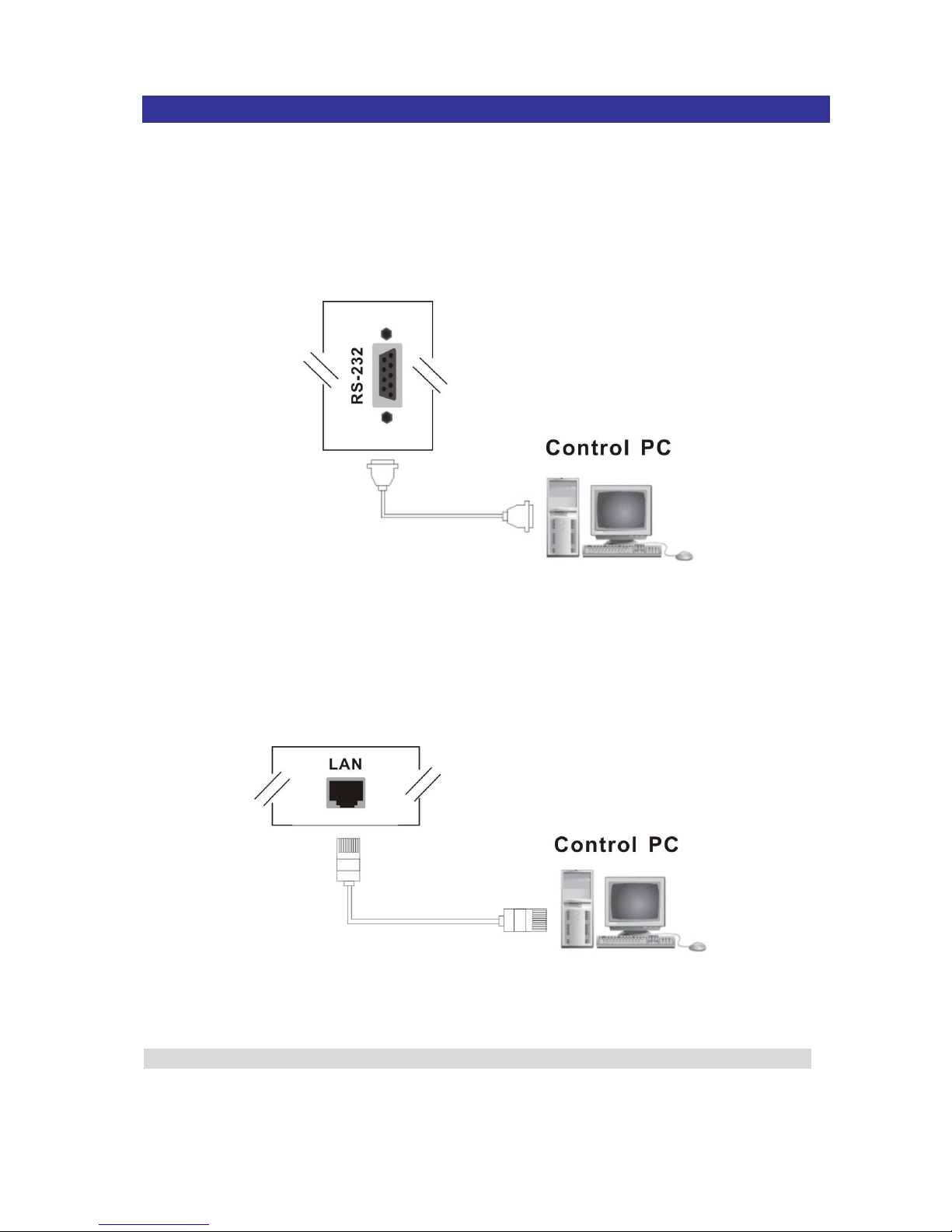
6.4 Remote Control Connection
Use the RS-232 connecting cable to connect the computer serial communication port
(COM1 or COM2) to the RS-232 communication port of the Switcher. The computer can
then be used to control the Switcher after installing of application software. Aside from
using the front panel keys for switching operation, you are also permitted to use the
RS-232 connection port for a remote operation.
Figure 6-4 RS-232 and Control PC connection
The Switcher also supports a LAN port allowing you to control all the series connection
devices through PC Browser.
Figure 6-5 LAN port and Control PC Connection
The Switcher supports RS-232 and LAN port on the rear panel for a remote control.
Page 19
V
V
V
P
P
P
-
-
-
6
6
6
0
0
0
2
2
2
H
H
H
H
H
H
T
T
T
U
U
U
18
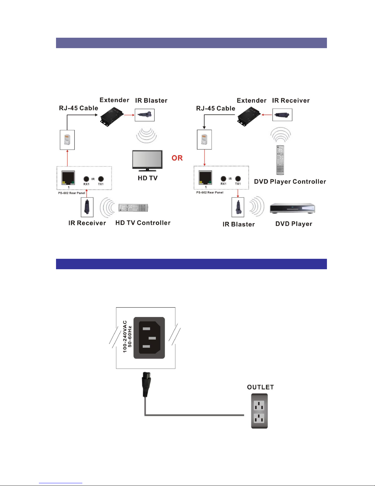
6.5 IR Pass-Through Connection
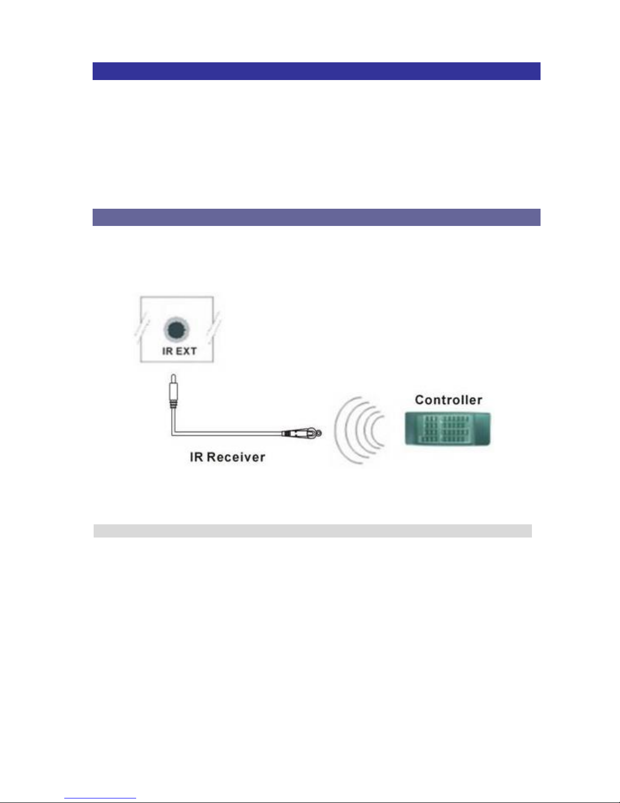
The Switcher provides an IR Receiver cable and IR Blaster cable accessories for IR
pass-through; on the other hand, it also provides you an extended IR pass-through
transmission through Extender.
- Supports you an IR channel to control the TV-end of your Switcher and Remote.
- Supports all kinds of IR frequency band
6.5.1 Normal IR Connection
The Switcher provides you an IR receiver for more convenient to react to the controller.
Please connect the receiver to the IR port located on the rear panel for optional position.
Figure 6-6 IR Extended Aiming
The package of this Switcher is not including the controller, the controller is optional.
Page 20
V
V
V
P
P
P
-
-
-
6
6
6
0
0
0
2
2
2
H
H
H
H
H
H
T
T
T
U
U
U
19
6.5.2 Extended IR Connection
Extended Connection:
You can extend the signal connection through the Extender described as below.
Figure 6-7 IR Extended Connection
6.6 Power Connection
Use the included power cord to connect from the power port on the rear panel of the
Switcher to the outlet.
Figure 6-8 Power Connection
Page 21
V
V
V
P
P
P
-
-
-
6
6
6
0
0
0
2
2
2
H
H
H
H
H
H
T
T
T
U
U
U
20
6.7 Ports and Switchers
The Switcher provides standard RS-232 serial communication port as well as LAN for
remotely managing. Besides the front panel is ideally for the local switching, managing
and setting operation, the Switcher also provides Dip switcher for locally settings.
6.7.1 RS-232
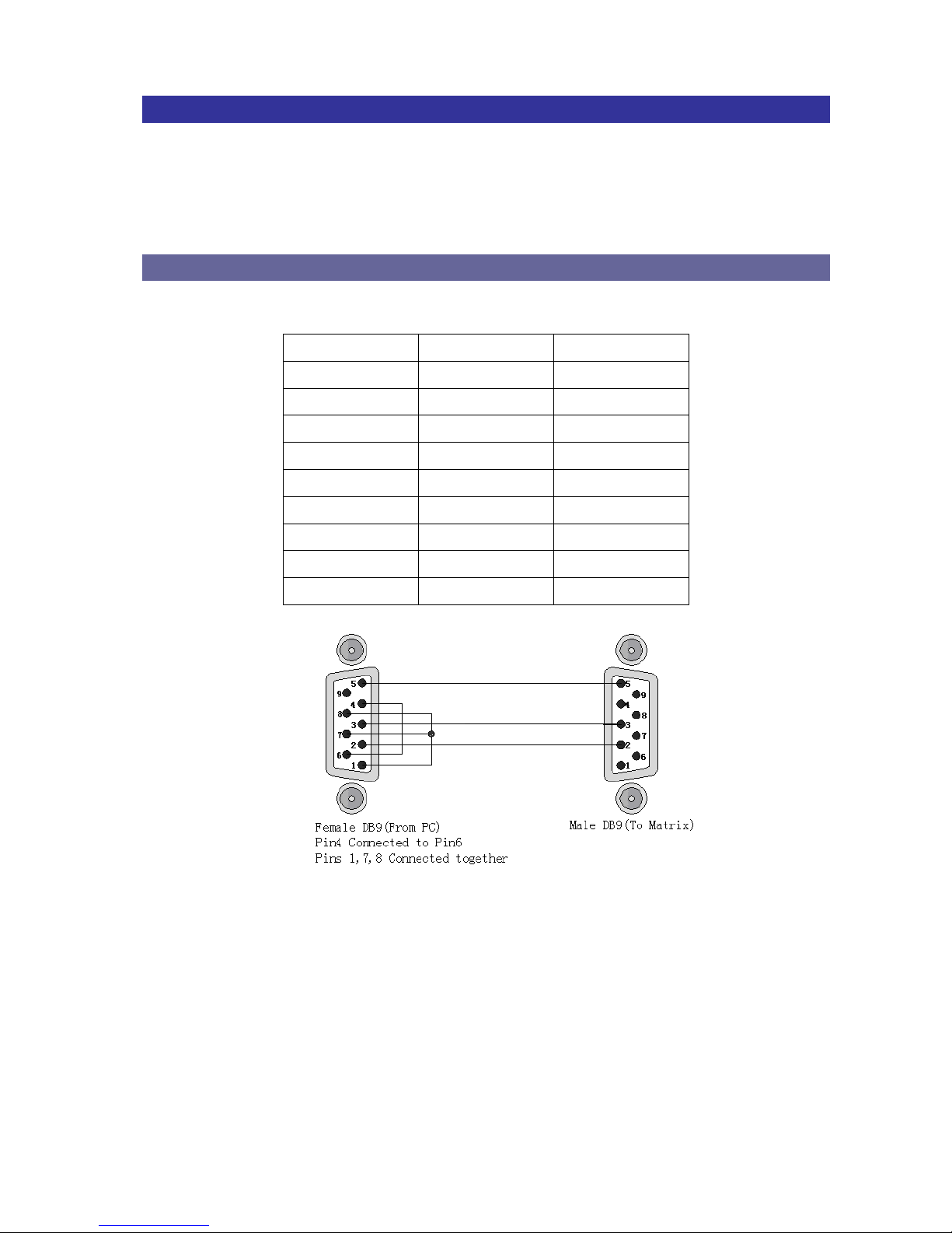
The RS-232 Pin functions are described as below:
Pin No.
Abbreviation
Description
1
N/u
Null
2
TXD
Send
3
RXD
Receive
4
N/u
Null
5
GND
Ground
6
N/u
Null
7
N/u
Null
8
N/u
Null
9
N/u
Null
Figure 6-8 (a)
Page 22
V
V
V
P
P
P
-
-
-
6
6
6
0
0
0
2
2
2
H
H
H
H
H
H
T
T
T
U
U
U
21
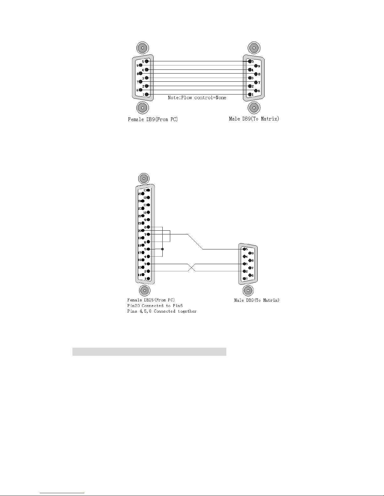
Figure 6-8 (b)
Figure 6-9
The Switcher RS-232 port is defined by DCE.
Page 23
V
V
V
P
P
P
-
-
-
6
6
6
0
0
0
2
2
2
H
H
H
H
H
H
T
T
T
U
U
U
22
6.7.2 HDBaseT Output Port
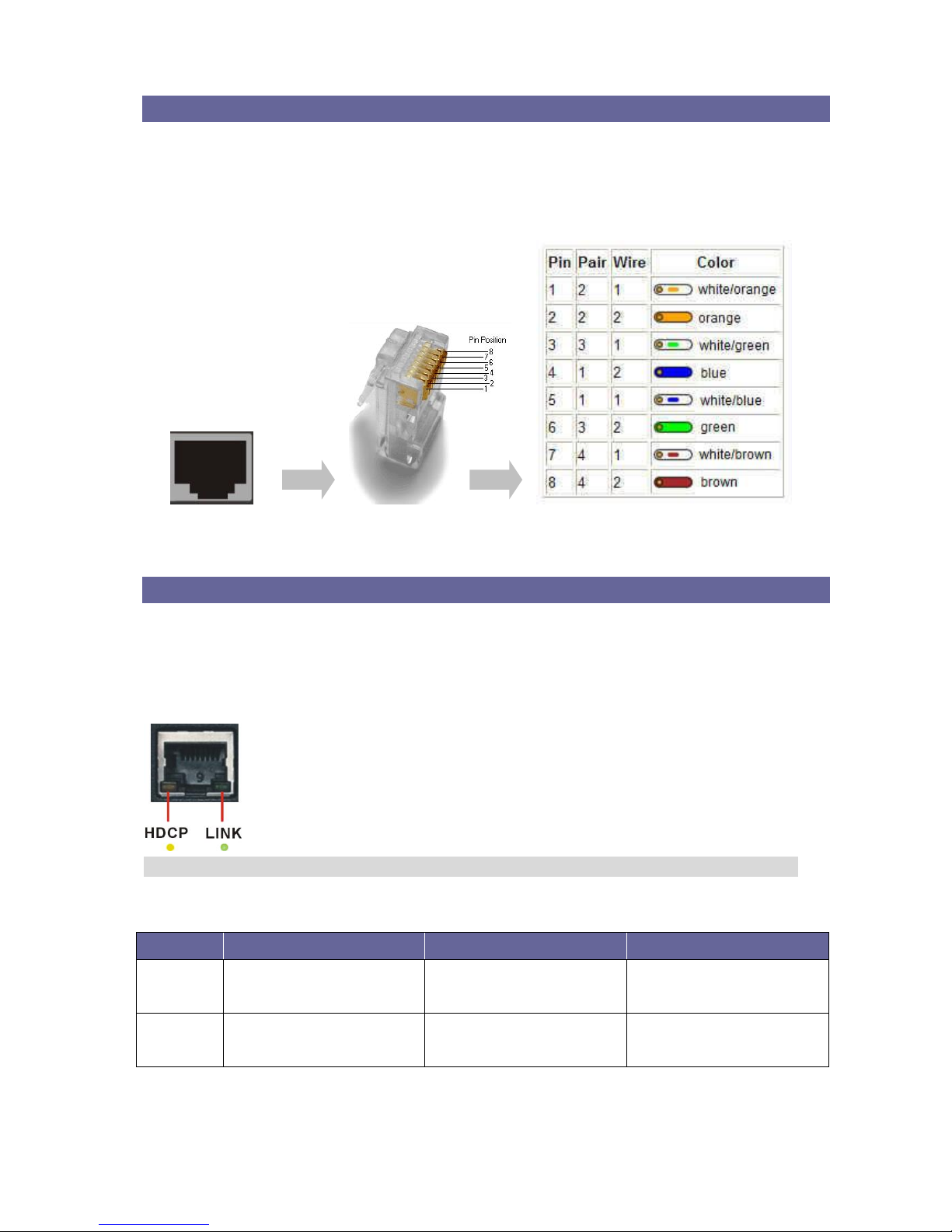
The Switcher supports RJ-45 registered jacks using 8P8C modular connector, which
specifies the physical male and female connectors as well as the pin assignments of the
wires in a LAN cable. (A common LAN cable is available.)
Figure 6-10 LAN (HDBT) Port
6.7.3 Output LED
The Switcher supports HDBaseT output for a long distance signal transmission. Output
connector is RJ-45 jack with two LED indicators. The LED indicators show you the status
of output transmission.
* The left of RJ-45 output jack is specified for HDCP LED (Yellow).
* The right of RJ-45 output jack is specified for LINK LED (Green).
The LED indicators are only designed for the Output – RJ-45 jack of the Switcher.
LED Indicators:
LED
Off
Blink
On
LINK
(Green)
No Link
Low Power Mode
HDBaseT Link
HDCP
(Yellow)
No HDMI Signals
No Encryption
HDCP Encryption
Page 24

V
V
V
P
P
P
-
-
-
6
6
6
0
0
0
2
2
2
H
H
H
H
H
H
T
T
T
U
U
U
23
6.7.4 Output Cable
HDBaseT was designed to provide Full HD performance up to 100/70 meters of Cat.5e
or superior cables. In a typical installation, the cable is stretched to its full length between
the HDBaseT Transmitter device and the HDBaseT Receiver device. However
sometimes, especially, in demonstrations or in a lab environment, the cable is rolled
randomly in small turns for convenience. The randomly rolled UTP cable suffers
additional signal impairments (compared to straight cable) and therefore the maximal
operating reach might be reduced. When a Cat.5e cable is randomly rolled, it is
recommended to limit its length to approximate 50 meters. Rolling a Cat.5e cable around
a 70cm fixed diameter plastic drum has just a minor effect on the FEXT (Far End Cross
Talk) when compared to a fully stretched cable.
Figure 6-11 Output LAN Cable
The VS010 family features the following:
When the VS010 is in low power mode (LPPF1/2), the sample rate of the PDIF channel
is reduced to 100 KHz. This implies that high data rates may not be used when the
VS010 is in LPPF.
Enables 10.2 Gbps of HDMI 1.4 traffic (including HDCP) over a single LAN cable
according to the following specifications:
Cable Type
Range
Supported Video
CAT5e/CAT6
60 meters
Most common full HD formats:
- Up to 1080P, 60Hz, 36bpp
- Data rates lower than 5.3 Gbps or below
225 MHz TMDS clock
CAT6a/CAT7
70 meters
CAT5e/CAT6
35 meters
Ultra HD video formats:
- Deep color: 1080P, 60Hz, 48bpp
- 4K x 2K
- Data rates higher than 5.3 Gbps or above
225MHz TMDS clock
CAT6a/CAT7
40 meters
Full HD support: 1080P@60Hz@48b/pixels, 3D, 4K x 2K
Page 25
V
V
V
P
P
P
-
-
-
6
6
6
0
0
0
2
2
2
H
H
H
H
H
H
T
T
T
U
U
U
24
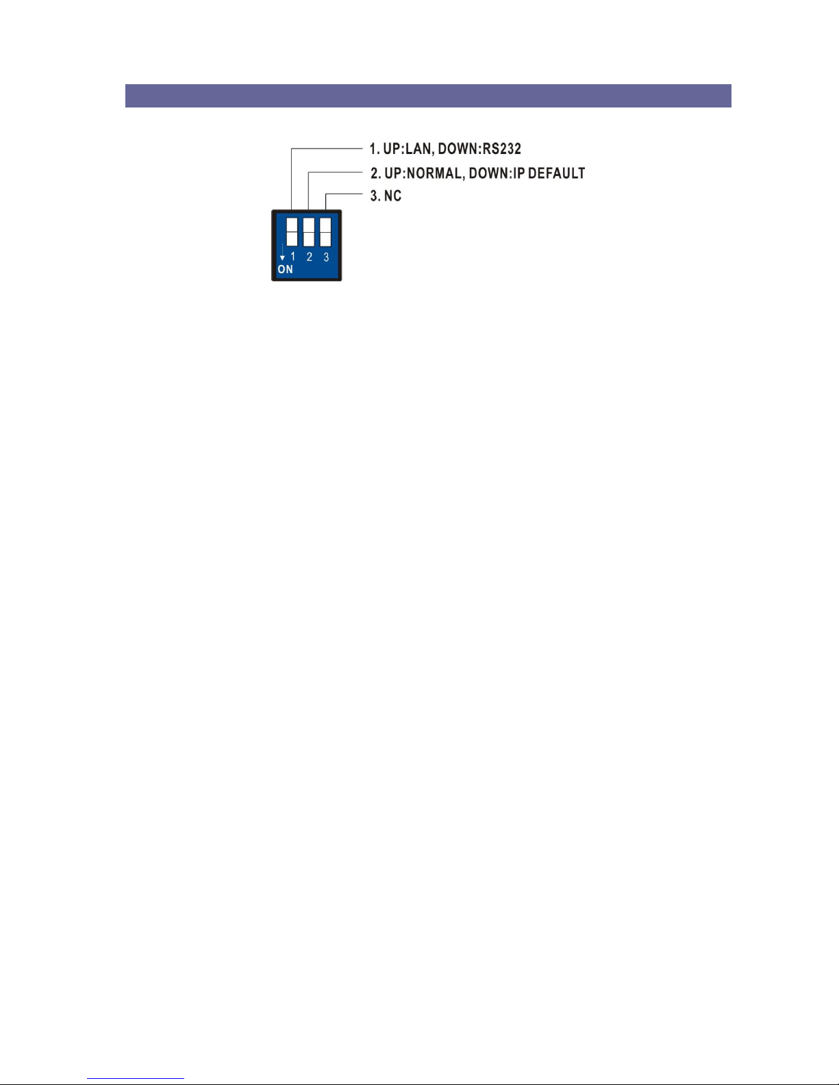
6.7.5 DIP Switcher for 3 Pins
Figure 6-12 DIP Switcher for 3 Pins
A. DIP Switcher Pin 1: Switch between RS-232 port and LAN port connection. The
default value is up specified “UP (OFF)” for LAN port connection.
DOWN (ON): RS232
UP (OFF): LAN
B. DIP Switcher Pin 2: Reset the web server IP address to 192.168.0.3, the default
value is up specified “UP (OFF)” for NORMAL IP configuration. For a normal operation,
please adjust the Pin2 to DOWN (ON), then power on the Switcher again. The IP
address will be restored to the default value: 192.168.0.3.
Page 26
V
V
V
P
P
P
-
-
-
6
6
6
0
0
0
2
2
2
H
H
H
H
H
H
T
T
T
U
U
U
25
CHAPTER 7 REMOTE CONFIGURATIONS
7.1 Telnet Commands
You can operate and configure the Switcher via a remote terminal session using Telnet.
Follow the steps as below to log into the Switcher by means of a Telnet session:
1. Connect the Switcher to LAN port of your network with RJ-45 cable.
2. Power on both Switcher and control PC.
3. Open a terminal session (command line) on your control PC.
4. At the prompt, key in the Switcher’s IP address as below:
TELNET [IP Address]:192.168.0.3
5. Press Enter
Please switch the DIP Switcher PIN 1 to UP (OFF) for LAN configuration.
7.1.1 Command List and Reboot
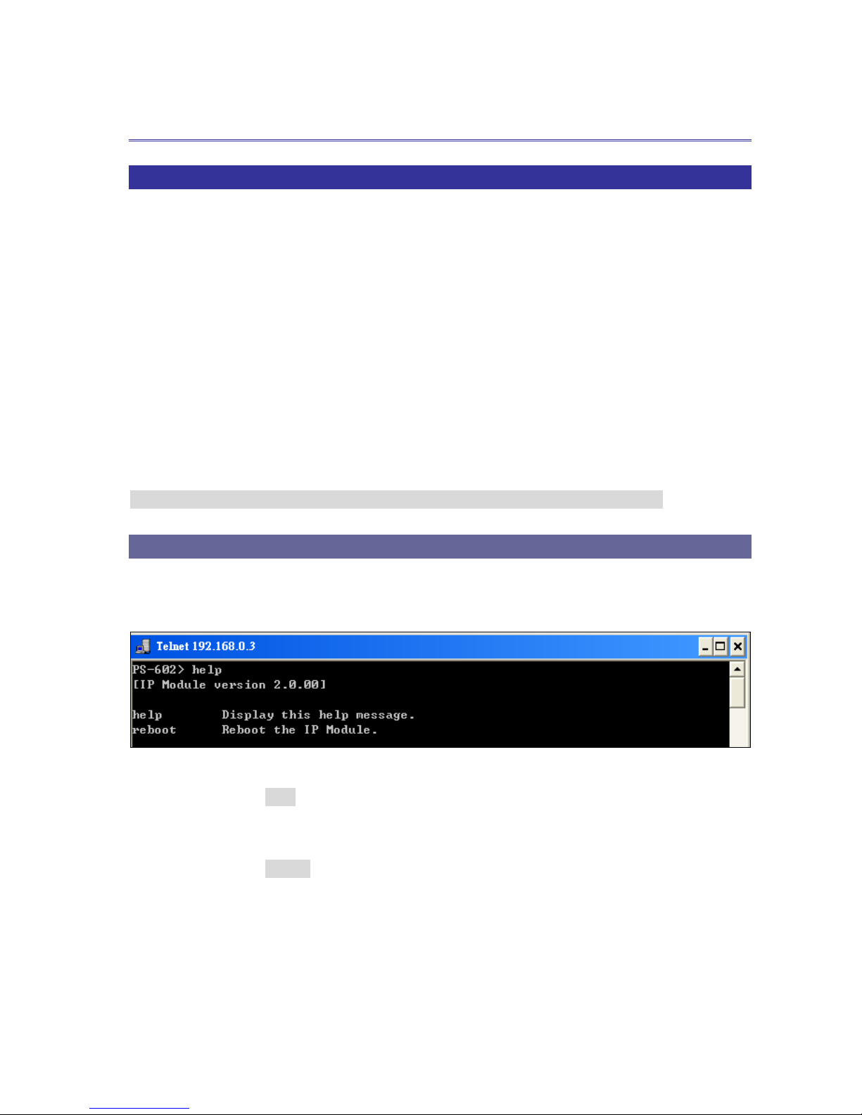
Once the connection with Switcher is established, the VP-602HHTU Telnet prompt
screen will appear, type help [Enter] to show the command list.
- Display the command list.
VP-602HHTU> help [Enter]
- Reboot the IP Module.
VP-602HHTU> reboot [Enter]
Page 27
V
V
V
P
P
P
-
-
-
6
6
6
0
0
0
2
2
2
H
H
H
H
H
H
T
T
T
U
U
U
26
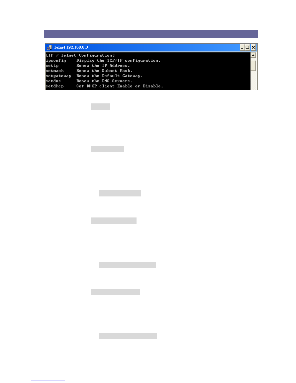
7.1.2 IP/Telnet Configuration
- Display the TCP/IP configuration
VP-602HHTU> ipconfig [Enter]
Current IP: 192.168.0.3
Current IP Mask: 255.255.255.0
Current Gateway: 192.168.0.1
- Renew the IP Address
VP-602HHTU> setip [ip addr] [Enter]
[ip addr]: xxx.xxx.xxx.xxx
Example:
Set IP address: 192.168.0.2
VP-602HHTU> setip 192.168.0.2 [Enter]
VP-602HHTU> setip IP address: 192.168.0.2
- Renew the Subnet Mask
VP-602HHTU> setmask [netmask] [Enter]
[netmask]: xxx.xxx.xxx.xxx
Example:
Set subnet mask address: 255.255.255.0
VP-602HHTU> setmask 255.255.255.0 [Enter]
VP-602HHTU> setmask Subnet Mask: 255.255.255.0
- Renew the Default Gateway
VP-602HHTU> setgateway [ip addr] [Enter]
[ip addr]: xxx.xxx.xxx.xxx
Example:
Set gateway address: 192.168.0.1
VP-602HHTU> setgateway 192.168.0.1 [Enter]
VP-602HHTU> setgateway Gateway: 192.168.0.1
Page 28

V
V
V
P
P
P
-
-
-
6
6
6
0
0
0
2
2
2
H
H
H
H
H
H
T
T
T
U
U
U
27
- Renew the DNS Servers
VP-602HHTU> setdns [ip addr] [Enter]
[ip addr]: xxx.xxx.xxx.xxx
Example:
Set DNS IP address: 192.168.0.1
VP-602HHTU> setdns 8.8.8.8 [Enter]
VP-602HHTU> setdns DNS IP:8.8.8.8
- Set DHCP Enable or Disable
VP-602HHTU> sethdcp [status] [Enter]
[status]: 0: Disable 1: Enable
Example:
Set DHCP to disable.
VP-602HHTU> setdhcp 0 [Enter]
VP-602HHTU> setdhcp DHCP Client: Disable
Please reboot to make the new values take effect.
Page 29
V
V
V
P
P
P
-
-
-
6
6
6
0
0
0
2
2
2
H
H
H
H
H
H
T
T
T
U
U
U
28
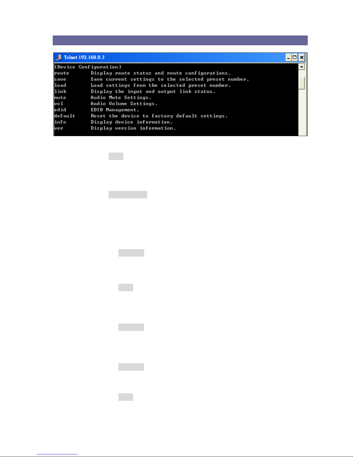
7.1.3 Device Configuration
- Display current route status
VP-602HHTU> route [Enter]
Output 01: Input = 03
Output 02: Input = 05
- Route configurations
VP-602HHTU> route [xx] [yy] [Enter]
xx – select output port, 0: select all outputs
yy – select input port, 0: disconnect
Example:
1. Set the output 2 and input 5.
VP-602HHTU> route 2 5 [Enter]
Output 02: Input = 05
Display reset route status.
VP-602HHTU> route [Enter]
Output 01: Input = 03
Output 02: Input = 05
2. Set all outputs to accept signals come from input 4.
VP-602HHTU> route 0 4 [Enter]
Output 01: Input = 04
Output 02: Input = 04
3. Disconnect the input signal to output 1.
VP-602HHTU> route 1 0 [Enter]
Output 01: Input = 00
Display reset route status.
VP-602HHTU> route [Enter]
Output 01: Input = 00
Output 02: Input = 05
Page 30

V
V
V
P
P
P
-
-
-
6
6
6
0
0
0
2
2
2
H
H
H
H
H
H
T
T
T
U
U
U
29
VP-602HHTU> route [yy] [Enter]
Route all outputs to the specified input.
Example:
Set all outputs to accept the signals come from input 5.
VP-602HHTU> route 6 [Enter]
Output 01: Input = 06
Output 02: Input = 06
VP-602HHTU> route [xx] [yy0] [yy1] …[yyn] [Enter]
Route output sequentially to the corresponding input.
Route output to the specified input yy0.
Route next 1 output to the specified input yy1.
Route next n output to the specified input yyn, n<=8
Example:
Set output 1 and 2 sequentially to the corresponding input 3 and 4.
VP-602HHTU> route 1 3 4 [Enter]
Output 01: Input = 03
Output 02: Input = 04
- Display the input and output link status
VP-602HHTU> link [Enter]
Output 01: Connected
Output 02: Connected
Output 03: Not Connected
Output 04: Not Connected
This command is used for HDMI Hot-Plug-Detect, when an HDMI signals is
detected, the resulting hot-plug detection instantiates a start-up communication
sequence. Output 01 and 02 are for local output (HDMI), Output 03 and 04 are for
remote output (HDBT)
- Display the mute status
VP-602HHTU> mute [Enter]
Audio 01: Volume is unmuted
Audio 02: Volume is unmuted
Audio 03: Volume is unmuted
Audio 04: Volume is unmuted
Audio 05: Volume is unmuted
Audio 06: Volume is unmuted
Audio 07: Volume is unmuted
Audio 08: Volume is unmated
Page 31

V
V
V
P
P
P
-
-
-
6
6
6
0
0
0
2
2
2
H
H
H
H
H
H
T
T
T
U
U
U
30
Audio 01, 03, 05 and 07 are specified for AUD OUT 1 (source/MIC1/MIC2/volume
knob) and Audio 02, 04, 06 and 08 are specified for AUD OUT 2 (source/MIC1/
MIC2/volume knob).
- Audio mute settings
VP-602HHTU> mute [xx] [yy] [Enter]
xx – select audio signal, 0: select all audio signals
yy – 1: mute, 0: unmute
Example:
1. Set audio 1 volume to mute.
VP-602HHTU> mute 1 1 [Enter]
Audio 01: Volume is muted
Display all audio volume status.
VP-602HHTU> mute [Enter]
Audio 01: Volume is muted
Audio 02: Volume is unmuted
Audio 03: Volume is unmuted
Audio 04: Volume is unmuted
Audio 05: Volume is unmuted
Audio 06: Volume is unmuted
Audio 07: Volume is unmuted
Audio 08: Volume is unmuted
2. Set all audio volume to mute.
VP-602HHTU> mute 0 1 [Enter]
Audio 01: Volume is muted
Audio 02: Volume is muted
Audio 03: Volume is muted
Audio 04: Volume is muted
Audio 05: Volume is muted
Audio 06: Volume is muted
Audio 07: Volume is muted
Audio 08: Volume is muted
3. Set all audio volume to unmute.
VP-602HHTU> mute 0 0 [Enter]
Audio 01: Volume is unmuted
Audio 02: Volume is unmuted
Audio 03: Volume is unmuted
Audio 04: Volume is unmuted
Audio 05: Volume is unmuted
Audio 06: Volume is unmuted
Audio 07: Volume is unmuted
Page 32

V
V
V
P
P
P
-
-
-
6
6
6
0
0
0
2
2
2
H
H
H
H
H
H
T
T
T
U
U
U
31
Audio 08: Volume is unmuted
VP-602HHTU> mute [yy] [Enter]
Set all audio volume to mute status
Example:
Set all audio volume to mute.
VP-602HHTU> mute 1 [Enter]
Audio 01: Volume is muted
Audio 02: Volume is muted
Audio 03: Volume is muted
Audio 04: Volume is muted
Audio 05: Volume is muted
Audio 06: Volume is muted
Audio 07: Volume is muted
Audio 08: Volume is muted
VP-602HHTU> mute [xx] [yy0] [yy1] … [yyn] [Enter]
Set audio sequentially to the corresponding volume status
Set audio xx volume status to yy0
Set next 1 audio volume status to yy1
Set next n audio volume status to yyn, n <= 8
Example:
Set specified audio volume to mute or unmute.
VP-602HHTU> mute 3 0 1 0 1 [Enter]
Audio 01: Volume is muted
Audio 02: Volume is muted
Audio 03: Volume is unmuted
Audio 04: Volume is muted
Audio 05: Volume is unmuted
Audio 06: Volume is muted
Audio 07: Volume is muted
Audio 08: Volume is muted
- Display the volume status
VP-602HHTU> vol [Enter]
Audio 01: Volume = 0
Audio 02: Volume = 0
Audio 03: Volume = 0
Audio 04: Volume = 0
Audio 05: Volume = 0
Audio 06: Volume = 0
Audio 07: Volume = 0
Audio 08: Volume = 0
Page 33

V
V
V
P
P
P
-
-
-
6
6
6
0
0
0
2
2
2
H
H
H
H
H
H
T
T
T
U
U
U
32
Audio 01, 03, 05 and 07 are specified for AUD OUT 1 (source/MIC1/MIC2/volume
knob) and Audio 02, 04, 06 and 08 are specified for AUD OUT 2 (source/MIC1/
MIC2/volume knob).
- Audio volume settings
VP-602HHTU> vol [xx] [yy] [Enter]
Set specified audio volume level
xx – select audio signal port, 0: select all signals index
yy – volume level, 0: mute
Example:
1. Set audio 2 volume level to 24.
VP-602HHTU> vol 2 24 [Enter]
Audio 02: Volume = 24
Display all audio volume level status.
VP-602HHTU> vol [Enter]
Audio 01: Volume = 0
Audio 02: Volume = 24
Audio 03: Volume = 0
Audio 04: Volume = 0
Audio 05: Volume = 0
Audio 06: Volume = 0
Audio 07: Volume = 0
Audio 08: Volume = 0
2. Set all audio volume level to 15.
VP-602HHTU> vol 0 15 [Enter]
Audio 01: Volume = 15
Audio 02: Volume = 15
Audio 03: Volume = 15
Audio 04: Volume = 15
Audio 05: Volume = 15
Audio 06: Volume = 15
Audio 07: Volume = 15
Audio 08: Volume = 15
3. Set audio 3 volume level to 0 (mute).
VP-602HHTU> vol 3 0 [Enter]
Audio 03: Volume = 0
Display all audio volume level status.
VP-602HHTU> vol [Enter]
Audio 01: Volume = 15
Page 34

V
V
V
P
P
P
-
-
-
6
6
6
0
0
0
2
2
2
H
H
H
H
H
H
T
T
T
U
U
U
33
Audio 02: Volume = 15
Audio 03: Volume = 0
Audio 04: Volume = 15
Audio 05: Volume = 15
Audio 06: Volume = 15
Audio 07: Volume = 15
Audio 08: Volume = 15
VP-602HHTU> vol [yy] [Enter]
Set all audio to the specified volume level
Example:
Set all audio volume level to 20.
VP-602HHTU> vol 20 [Enter]
Audio 02: Volume = 20
Display all audio volume status.
VP-602HHTU> vol [Enter]
Audio 01: Volume = 20
Audio 02: Volume = 20
Audio 03: Volume = 20
Audio 04: Volume = 20
Audio 05: Volume = 20
Audio 06: Volume = 20
Audio 07: Volume = 20
Audio 08: Volume = 20
VP-602HHTU> vol [xx] [yy0] [yy1] … [yyn] [Enter]
Set audio signal sequentially to the corresponding volume level
Set audio xx volume level to yy0
Set next 1 audio volume level to yy1
Set next n audio volume level to yyn, n <= 8
Example:
Set the specified audio to specific volume level. Set the audio 2 volume level to 1 and
others to specific values sequentially.
VP-602HHTU> vol 2 1 2 3 4 5 6 7 [Enter]
Audio 01: Volume = 20
Audio 02: Volume = 1
Audio 03: Volume = 2
Audio 04: Volume = 3
Audio 05: Volume = 4
Audio 06: Volume = 5
Audio 07: Volume = 6
Audio 08: Volume = 7
Page 35
V
V
V
P
P
P
-
-
-
6
6
6
0
0
0
2
2
2
H
H
H
H
H
H
T
T
T
U
U
U
34
- Display EDID status
VP-602HHTU> edid [Enter]
Input 01: EDID = 00
Input 02: EDID = 00
- EDID management
VP-602HHTU> edid <input> <edid> [Enter]
<input>: select input port, 0: select all inputs
<edid>: select edid source, 0: default 1080P and 2ch audio
VP-602HHTU does not support EDID adjustment of individual input port.
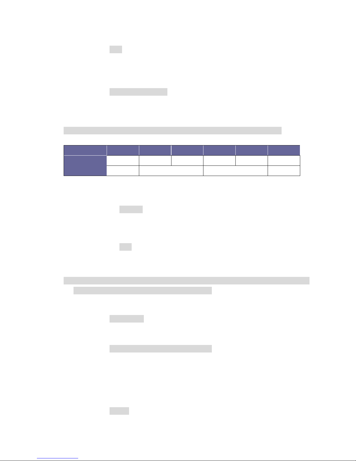
EDID Value
0 1 2 3 4
5
Description
1080P
OUT1
OUT2
OUT1
OUT2
720P
Default
Local Output
Remote Output
Default
Example:
Set input 1 to use the EDID comes from local output 2.
VP-602HHTU> edid 1 2 [Enter]
Input 01: EDID = 02
Display all EDID status.
VP-602HHTU> edid [Enter]
Input 01: EDID = 02
Input 02: EDID = 02
EDID values are from 0 up to 5 individual indicates the 1080P, OUT1 Local, OUT2
Local, OUT1 Remote, OUT2 Remote and 720P.
- All inputs using the specified EDID
VP-602HHTU> edid <edid> [Enter]
<edid>: select edid source, 0: default 1080P and 2ch audio
VP-602HHTU> edid <input> <edid 0> <edit 1> …. [Enter]
Specified input using the specified EDID 0 sequentially
Specified next 1 input using the specified EDID 1
Specified next n input using the specified EDID n, n <= 8
<edid>: select edid source, 0: default 1080P and 2ch audio
- Reset the device to factory default settings
VP-602HHTU> default [Enter]
Reset the device to factory default settings.
Page 36

V
V
V
P
P
P
-
-
-
6
6
6
0
0
0
2
2
2
H
H
H
H
H
H
T
T
T
U
U
U
35
- Display device information
VP-602HHTU> info [Enter]
Device Name: VP-602HHTU
Output Total: 2
Input Total: 6
Memory Total: 0
Support Link Status: Output
Support EDID management
Support audio control
- Display version information
VP-602HHTU> ver [Enter]
IP Module version 2.0.00
AV Matrix Protocol <API> version 2.30
Device Firmware version 1.0.00
7.1.4 AV Matrix Protocol Command
- Send AV Matrix protocol command <API>
VP-602HHTU> avm <instruction> <index> <value> [Enter]
<instruction>: AVM Protocol Byte 2
<index>: AVM Protocol Byte 3
<value>: AVM Protocol Byte 4
Example:
VP-602HHTU> avm 1 2 3 [Enter]
Response: ACK
Page 37

V
V
V
P
P
P
-
-
-
6
6
6
0
0
0
2
2
2
H
H
H
H
H
H
T
T
T
U
U
U
36
7.2 RS-232 Commands
You can also operate and configure the Switcher via a remote terminal session using
RS-232. Follow the steps as below to log into the Switcher by means of a RS-232
session (the example as below is for Hyper Terminal):
1. Connect the Switcher to your control PC with RS-232 cable.
2. Power on both Switcher and control PC.
3. Open the Hyper Terminal by clicking Start│Programs│Accessories
Communications│Hyper Terminal on your control PC.
4. The New Connection – Hyper Terminal screen will appear. Input the connection
name and select a representative icon. Then click OK.
5. Select the connecting port that you want to use, click OK. Default port is COM1.
6. Set the Bits per second to 9600, Data Bits to 8 (Default), Parity to None (Default), Stop
bits to 1 (Default) and flow control to None from the drop-down list, click OK.
Please switch the DIP Switcher PIN 1 to DOWN (ON) for RS-232 configuration.
Page 38
V
V
V
P
P
P
-
-
-
6
6
6
0
0
0
2
2
2
H
H
H
H
H
H
T
T
T
U
U
U
37
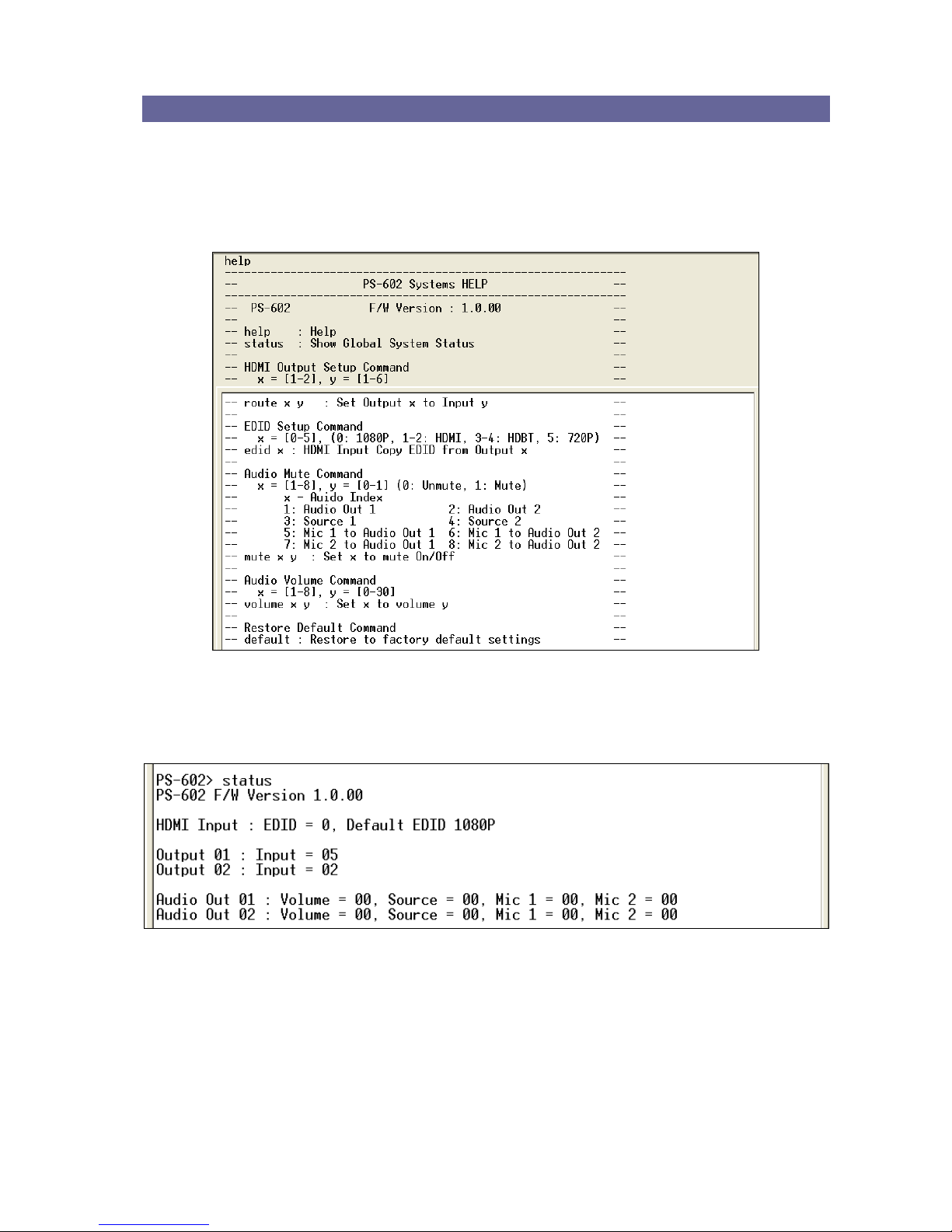
7.2.1 Commands List and Status
Once the connection with Switcher is established, type help in the Hyper Terminal
screen to show the command list.
- Show the command list
- Show the Status of Your Switcher
Page 39
V
V
V
P
P
P
-
-
-
6
6
6
0
0
0
2
2
2
H
H
H
H
H
H
T
T
T
U
U
U
38
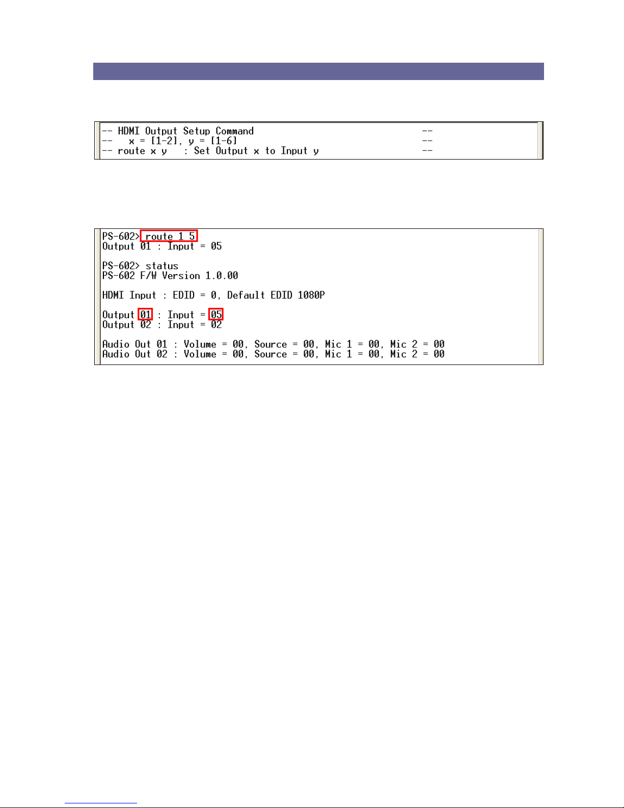
7.2.2 HDMI Command
- HDMI Output Setup Command
Example:
Set output 1 signal comes from input 5.
Page 40
V
V
V
P
P
P
-
-
-
6
6
6
0
0
0
2
2
2
H
H
H
H
H
H
T
T
T
U
U
U
39
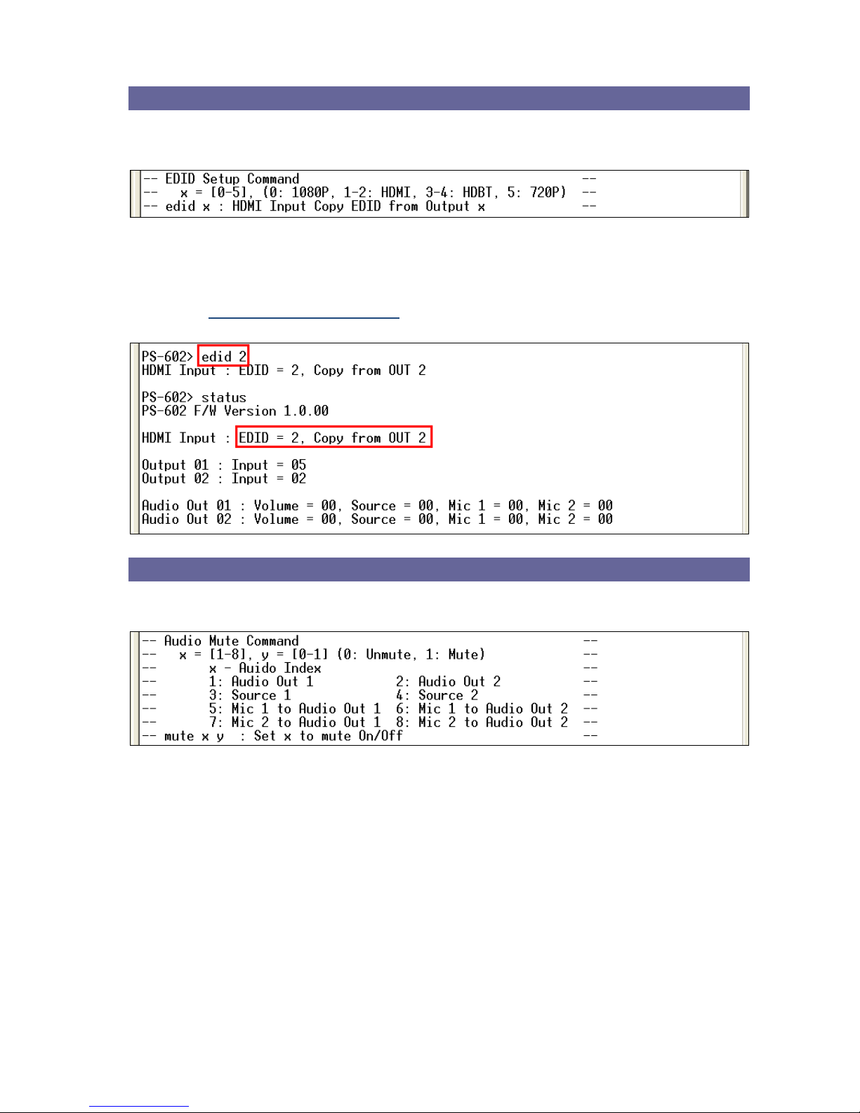
7.2.3 EDID Command
- EDID Setup Command
Example:
Set resolution copied from EDID output 2. For EDID value configurations, please
refer to 7.1.3 Device Configuration.
7.2.4 Audio Commands
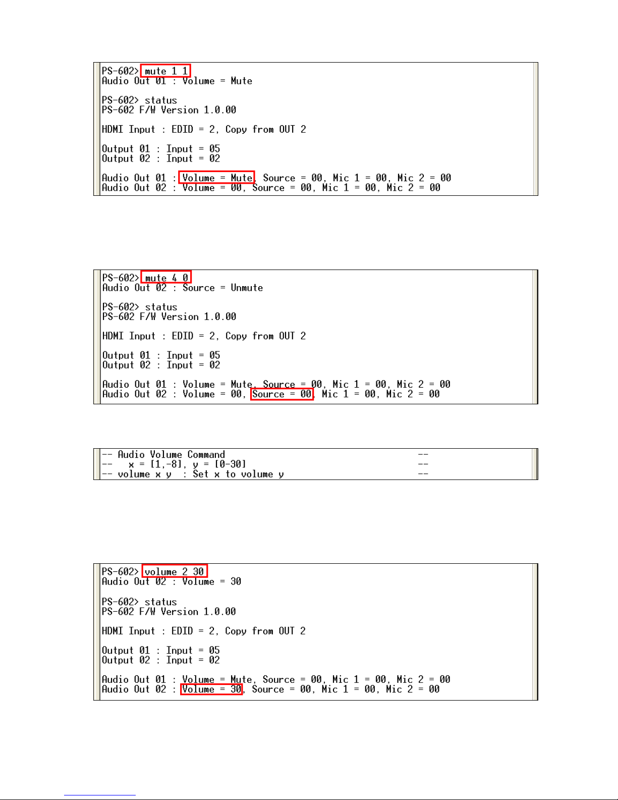
- Audio Mute Command
Example:
Set audio out 1 (audio out integrated status) to mute. The audio out 1 will show you
the integrated volume status is mute.
Page 41
V
V
V
P
P
P
-
-
-
6
6
6
0
0
0
2
2
2
H
H
H
H
H
H
T
T
T
U
U
U
40
Example:
Set audio out 2 (source status) to unmute. The audio out 2 will show you the source
volume level presently.
- Audio Volume Command
Example:
Set audio out 2 volume level (audio out integrated volume) to 30.
Example:
Page 42
V
V
V
P
P
P
-
-
-
6
6
6
0
0
0
2
2
2
H
H
H
H
H
H
T
T
T
U
U
U
41
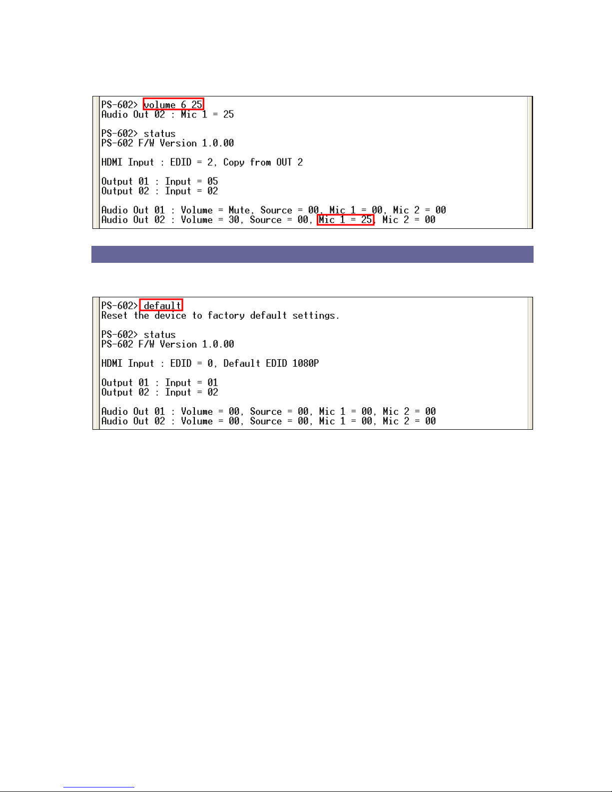
Set the MIC1 volume level for audio out 2 to 25. (Input source: MIC1 volume level=30,
Output port: audio out 2)
7.2.5 Restore Default Command
- Restore to Factory Default Settings
Page 43

V
V
V
P
P
P
-
-
-
6
6
6
0
0
0
2
2
2
H
H
H
H
H
H
T
T
T
U
U
U
42
CHAPTER 8 TROUBLESHOOTING
1. What to do if LCD is fail in display?
Answer: Check the connection of power cord is not loosening and the power cord is in a
good status having no any damage. Check the power source is normally.
2. What to do if the Switcher front panel keys switching not responsive?
Answer: The Switcher front panel keys employ scanning testing and require longer
response time. Press the keys for 2 seconds and then release. This way, key
switching will be responsive in operation.
3. What to do if the serial port (usually refer to the computer serial port) fails to control the
Switcher?
Answer: Check that the communication port set by the control software is correctly
connected to the corresponding serial port of the equipment. Also, check if the
computer communication port is in good order. Check the ID address and DIP
Switcher is configured correctly. Refer to 6.7.5 DIP Switcher for 3 Pins.
4. What to do if the corresponding audio signal fails to output during Switcher switching?
Answer:
(1) Check if there is signal on the input end. If there is no input signal, it could be that the
input connection cable is broken or the connector gets loosen. You are advised to
replace the connection cable.
(2) Check if there is signal on the output end. If there is no output signal, it could be that
the cable is broken or the connector gets loosen. You are advised to replace the
connection cable.
(3) Check if the output port number is the same as the controlled port number.
(4) Check the connections of input and output ports are correctly.
(5) If none of the above circumstances happen, it could be internal failure of the product
itself. You must send for repair by qualified technical engineers.
5. What to do if you sense the power leakage during plugging or unplugging of the
input/output ports?
Answer: It could be that the equipment power is not properly grounded. You must
properly ground your equipment; otherwise product life can easily be shortened.
Page 44

V
V
V
P
P
P
-
-
-
6
6
6
0
0
0
2
2
2
H
H
H
H
H
H
T
T
T
U
U
U
43
6. What to do if the Switcher panel keys and communication ports are out of order?
Answer: Check if the equipment power input is in good contact and the computer
communication ports are in good order. If yes, it could be some internal failure of the
product, please send for repair by qualified technical engineer.
7. What to do if operation and function failure occurred?
Answer: Check if the equipment and the Switcher system are in proper connection. If
the problem persists, send the product to the maintenance center for repair.
8. How to avoid the equipment failure due to the high temperature?
Answer: Place the equipment in a ventilate location. If it is still not to be improved,
please check with the build-in fan whether is damaged. Or contact your agency for
helping.
9. What to do if IR function failure occurred?
Answer: Check the battery of remote controller is NOT running low and the IR connector
is not loosening. Check whether the remote controller is aiming at the IR receiver
accurately.
Page 45
V
V
V
P
P
P
-
-
-
6
6
6
0
0
0
2
2
2
H
H
H
H
H
H
T
T
T
U
U
U
44
APPENDIX A HDBASET FIRMWARE UPGRADE
Process the Update TX_xxx.bat or UpdateRX_xxx.bat file to upgrade firmware. (xxx is
specified for firmware version) These files are used for upgrading the
VS010TX/VS010RX IC in your devices.
- The UpdateTX_xxx.bat file is used to upgrade the Switcher or D.A system (the
VS010TX IC in your Switcher) firmware.
- The UpdateRX_xxx.bat file is used to upgrade the Extender (the VS010RX IC in your
VE-70HHTW-F) firmware.
VE-70HHTW-F HDBaseT F/W Upgrade
Follow the steps as below to upgrade the Extender firmware:
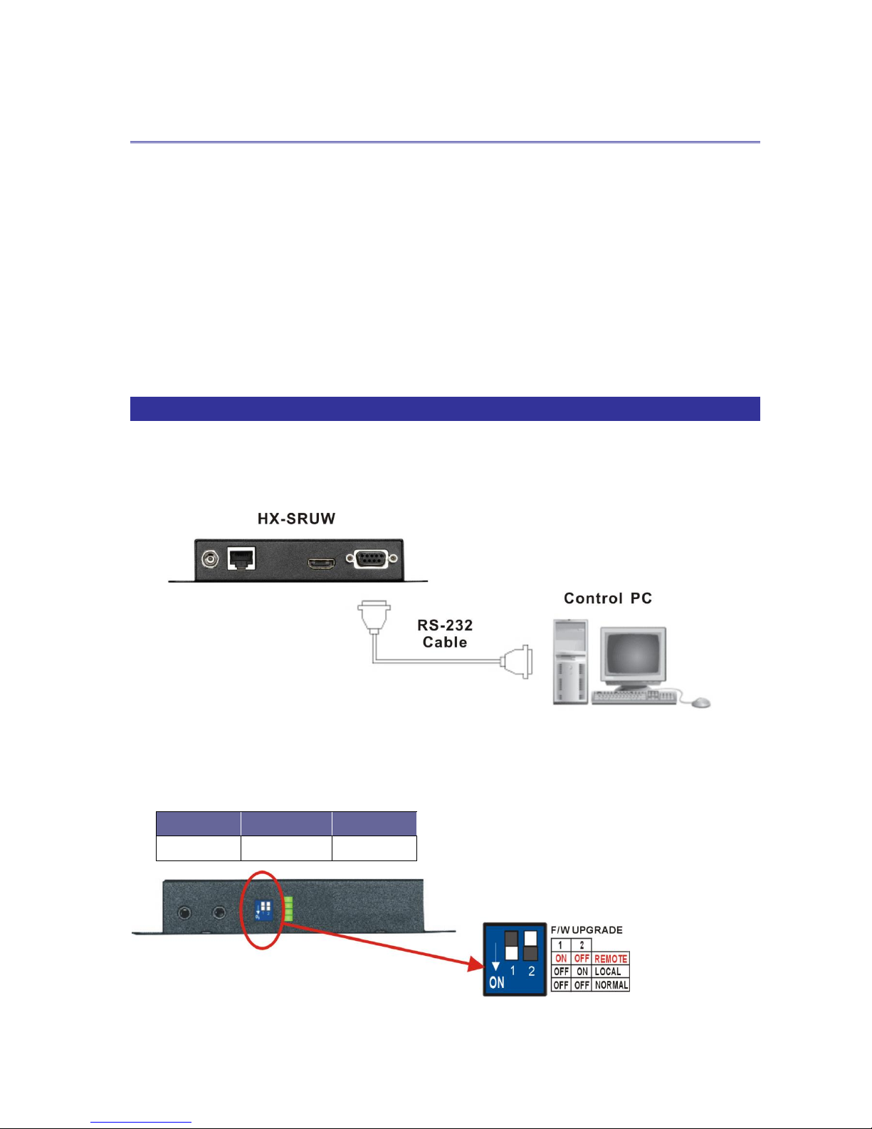
1. Connect the control PC and VE-70HHTW-F with a RS-232 cable.
2. Connect the DC 12V adapter
3. Adjust the F/W DIP switch on the Extender.
Remote (Receiver) Firmware Upgrade
Pin 1
Pin 2
REMOTE
ON
OFF
Page 46
V
V
V
P
P
P
-
-
-
6
6
6
0
0
0
2
2
2
H
H
H
H
H
H
T
T
T
U
U
U
45
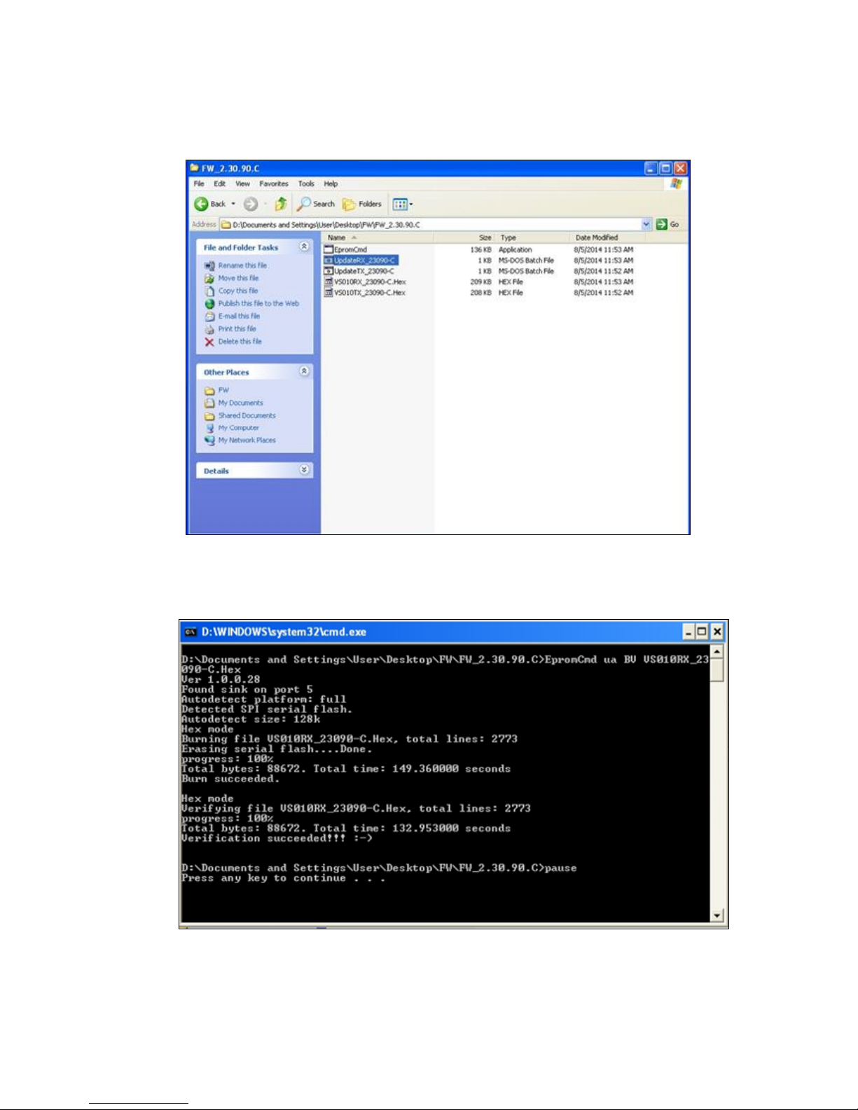
4. On the control PC, process the UpdateRX_23090-C.bat file to upgrade firmware.
(The update file name is only for reference, it will be different based on version.)
5. Final, the update is finished as below.
Page 47
V
V
V
P
P
P
-
-
-
6
6
6
0
0
0
2
2
2
H
H
H
H
H
H
T
T
T
U
U
U
46
Switcher HDBaseT F/W Upgrade
Follow the steps as below to upgrade the Switcher firmware:
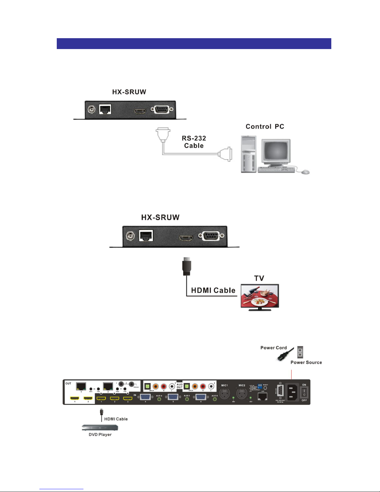
1. Connect the control PC and VE-70HHTW-F with a RS-232 cable.
2. Connect the TV and VE-70HHTW-F with a HDMI cable.
3. Connect the DVD Player and Switcher with a HDMI cable.
Page 48
V
V
V
P
P
P
-
-
-
6
6
6
0
0
0
2
2
2
H
H
H
H
H
H
T
T
T
U
U
U
47
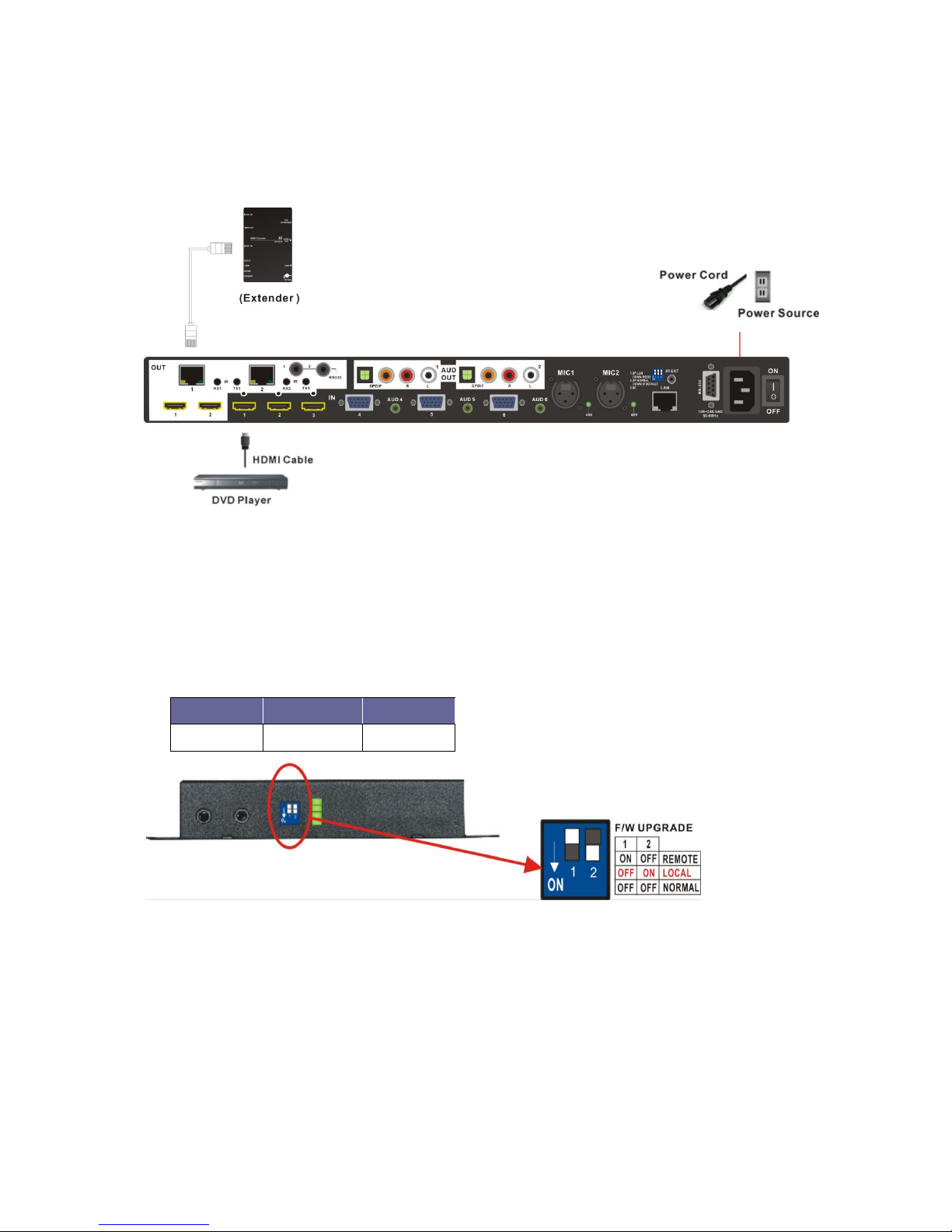
4. Connect the LAN cable to the LINK IN port on the panel of Switcher. The other end of
the LAN cable connected to the OUTPUT port of Switcher.
5. Connect the DC 12V adapter.
6. Enable the Switcher, TV and DVD player power, and play the video comes from the
DVD Player.
7. Adjust the VE-70HHTW-F F/W Upgrade switcher to LOCAL mode.
Local (Switcher) Firmware Upgrade
Pin 1
Pin 2
LOCAL
OFF
ON
Page 49
V
V
V
P
P
P
-
-
-
6
6
6
0
0
0
2
2
2
H
H
H
H
H
H
T
T
T
U
U
U
48
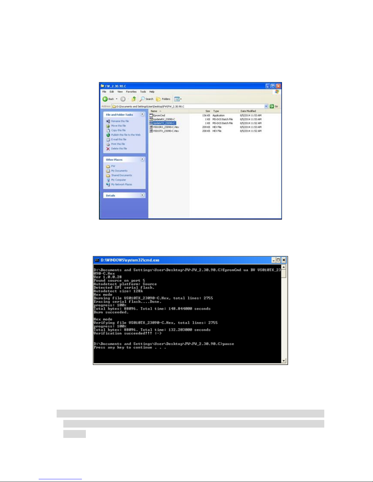
8. On the control PC, process the UpdateTX_23090-C.bat file to upgrade firmware.
(The update file name is only for reference, it will be different based on version.)
9. Final, the update is finish as below.
10. Each procedure only updates one port; please follow the same procedures to update
other OUT ports.
Implementation of the Switcher HDBaseT F/W Upgrade should be at the active status
(the video playing on TV is normal display). Otherwise, it will enter power-saving
mode.
Page 50
V
V
V
P
P
P
-
-
-
6
6
6
0
0
0
2
2
2
H
H
H
H
H
H
T
T
T
U
U
U
49
APPENDIX B EXTENDER
The extension of HDMI video signal device supports up to 70 meters away by using an
Extender and Cat.5e cable.
HDMI Extender is ideal for:
Test bench facilities
Data Center
Help desks
VE-70HHTW-F Extender
Side View
Side View
Page 51
V
V
V
P
P
P
-
-
-
6
6
6
0
0
0
2
2
2
H
H
H
H
H
H
T
T
T
U
U
U
50
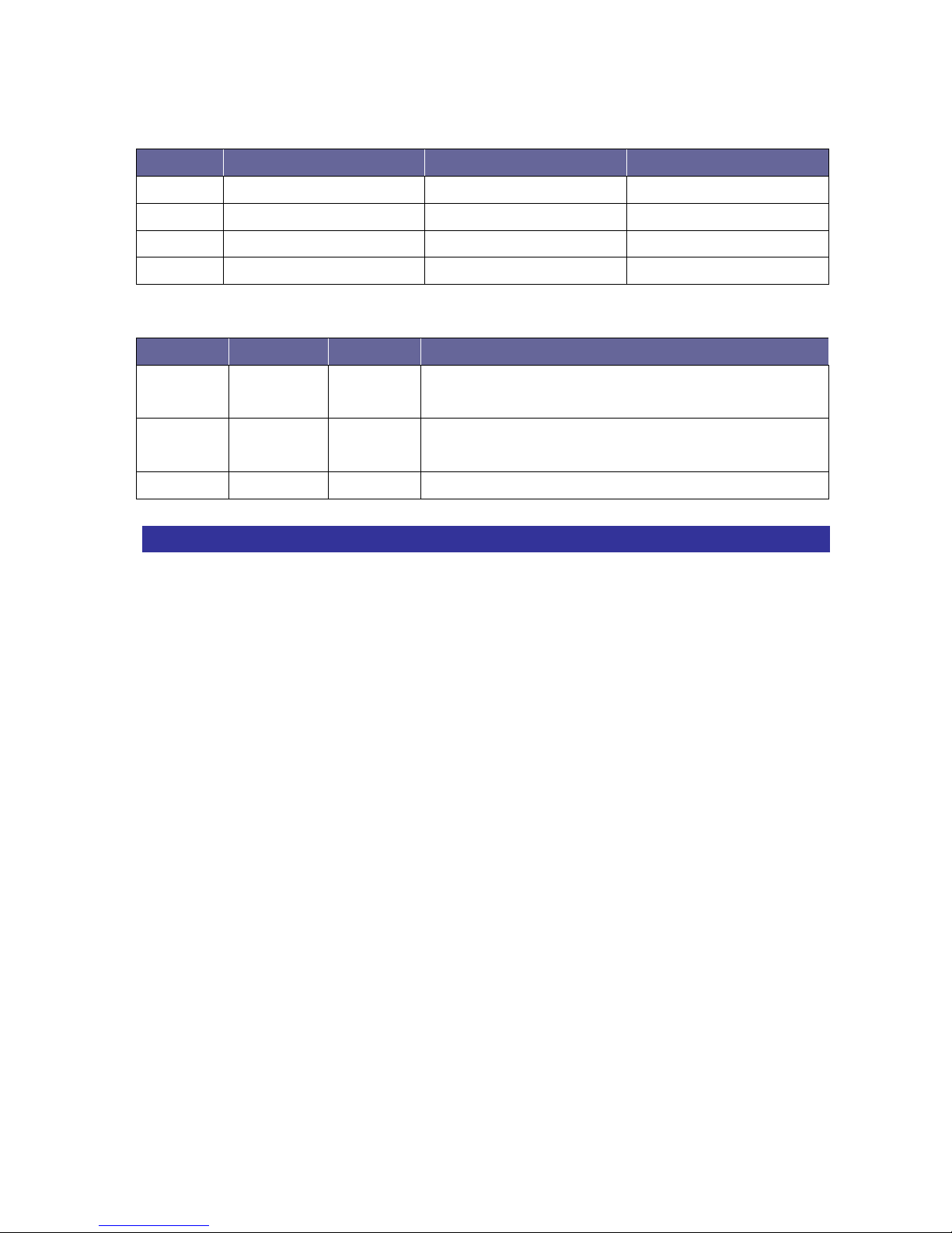
LED Indicators (Green):
LED
Off
Blink
On
MODE
-
Power Connected
-
LINK
No Link
Low Power Mode
HDBaseT Link
HDCP
No HDMI Signals
No Encryption
HDCP Encryption
POWER
Power Off
-
Power On
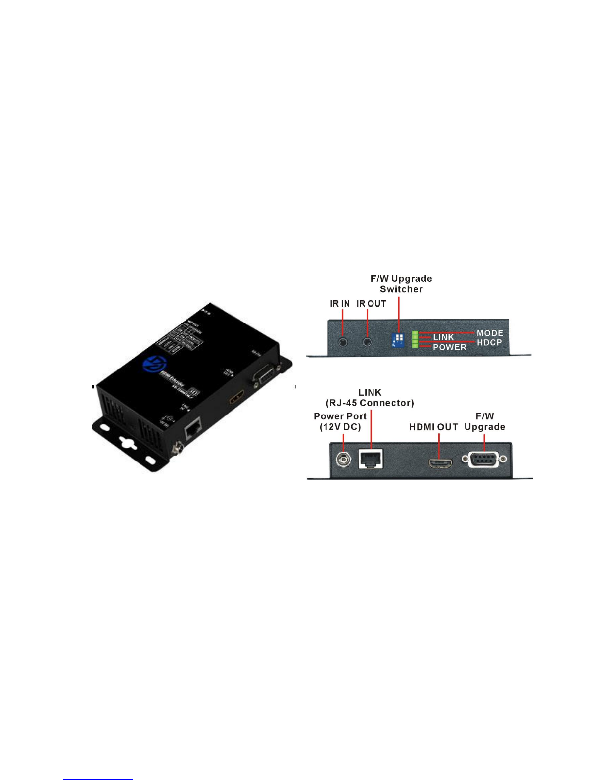
VE-70HHTW-F Extender: F/W Upgrade Switcher (2-Pin)
Pin 1
Pin 2
Description
REMOTE
ON
OFF
Through the RS-232 connection to upgrade
Receiver unit.
LOCAL
OFF
ON
Through the LAN Connection to upgrade
Transmitter (VP-602HHTU).
NORMAL
OFF
OFF
Extend the RS-232 Signal Transmission
Features
Through the Extender, you can use the output of the Switcher to display identical
image and extension of HDMI signal up to 70 meters on HDTV
HDCP Compliant
Supports F/W Upgrade (Optional)
Supports 3D pass-through
Supports all frequency band IR pass-through
Supports IR/RS-232 extension function.
One Cat.5e cable extension
Supports resolution up to 4K x 2K
HDBaseT technology
Use Cat.5e cable to install easily
Page 52

V
V
V
P
P
P
-
-
-
6
6
6
0
0
0
2
2
2
H
H
H
H
H
H
T
T
T
U
U
U
51
Specifications
Hardware
HDMI OUT
HDMI A-Type Female x 1
LINK
RJ-45 Connector x 1
IR OUT
3.5ψ Stereo Jack x 1
IR IN
3.5ψ Stereo Jack x 1
2 Pins Dip Switch
F/W Upgrade Setting
RS-232 Connector
DB9 Female x 1 (For F/W Upgrade)
LED indicators
MODE/LINK/HDCP/POWER
Power Supply
DC 12V with Lock
Housing
Metal
Weight
308g
Dimensions (LxWxH)
150x80x35mm
Multimedia
Max. Resolution
4K x 2K@30Hz, 8-bit
Highest TMDS Frequency
300MHz
Control Information
HDMI Cable Distance
10 meters (At least)
Cat.5e Cable Distance
70 meters (Max.)
Remote Control
IR Receiver, IR Blaster
Page 53
V
V
V
P
P
P
-
-
-
6
6
6
0
0
0
2
2
2
H
H
H
H
H
H
T
T
T
U
U
U
52
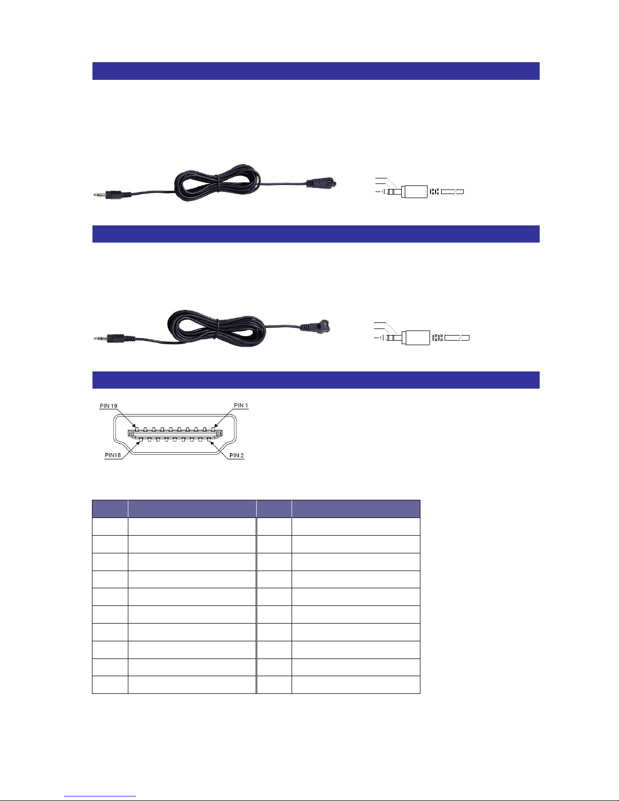
IR Receiver Cable Directions
Put IR Receiver cable into the Receiver “IR IN” port and place the IR Receiver Cable, so
that you can aim at it easily with your IR remote controller.
IR Receiver Cable:
GND
+V
Sig
IR Blaster Cable Directions
Plug IR Blaster cable into Receiver “IR OUT” port located on the front-panel.
IR Blaster Cable:
NC
P+
N-
HDMI Output Connector
HDMI Type A Connector host assignment:
Pin #
Signal
Pin #
Signal
1
TMDS Data 2+
11
TMDS Clock Shield
2
TMDS Data 2 Shield
12
TMDS Clock -
3
TMDS Data 2-
13
NC 4 TMDS Data 1+
14
NC 5 TMDS Data 1 Shield
15
DDC SCL
6
TMDS Data 1-
16
DDC SDA
7
TMDS Data 0+
17
DDC/CEC Ground
8
TMDS Data 0 Shield
18
+5V Power
9
TMDS Data 0-
19
Hot Plug Detect
10
TMDS Clock+
Page 54
V
V
V
P
P
P
-
-
-
6
6
6
0
0
0
2
2
2
H
H
H
H
H
H
T
T
T
U
U
U
53
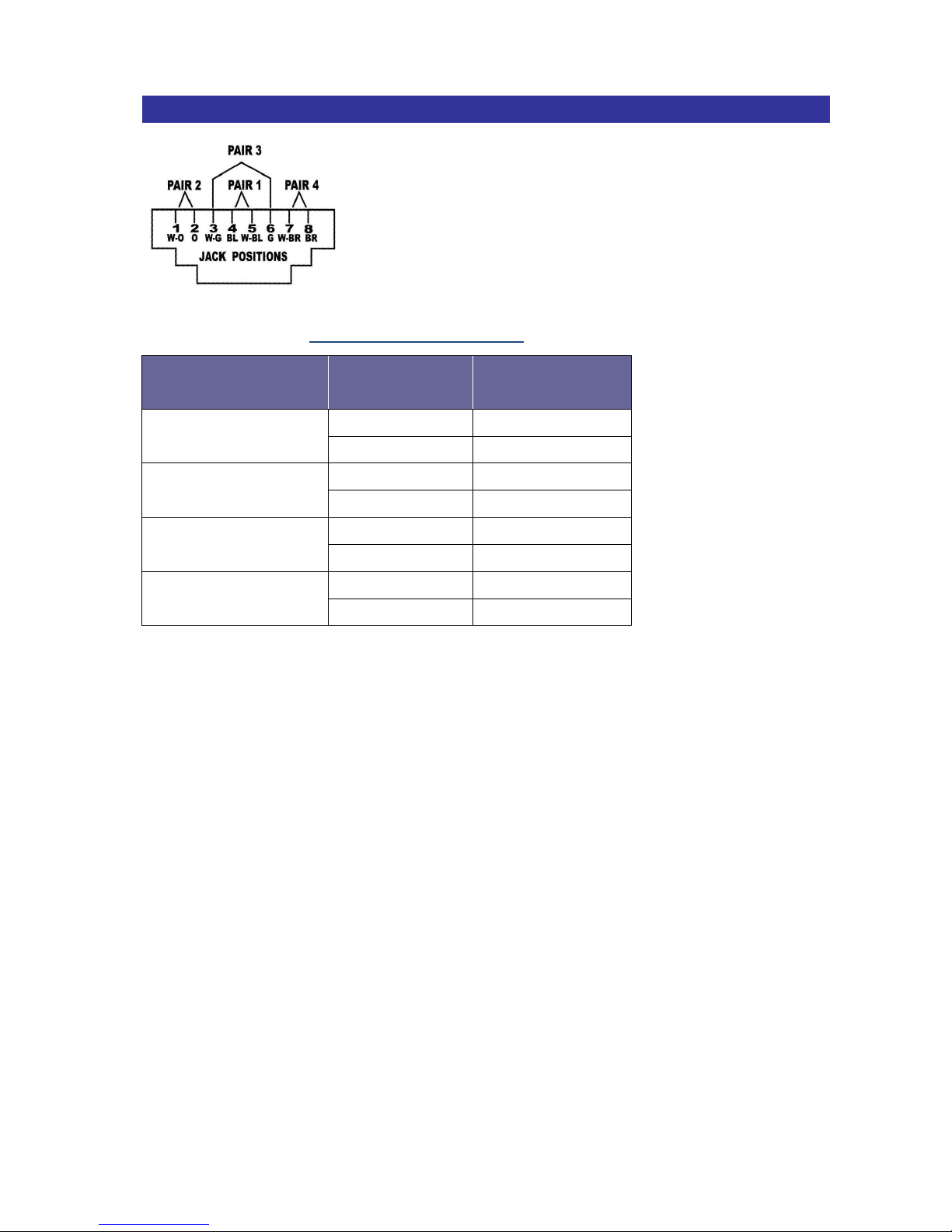
Wiring Information for Link Connector
You can also refer to 6.7.2 HDBaseT Output Port
Conductor
Identification
RJ-45 Pin
Assignment
Color Code for
Conductor
Pair 1
5
White-Blue
4
Blue
Pair 2
1
White-Orange
2
Orange
Pair 3
3
White-Green
6
Green
Pair 4
7
White-Brown
8
Brown
Page 55
V
V
V
P
P
P
-
-
-
6
6
6
0
0
0
2
2
2
H
H
H
H
H
H
T
T
T
U
U
U
54
APPENDIX C FIRMWARE UPGRADE
This Chapter will introduce you how to upgrade firmware on your web browser. For
firmware upgrade, you have to upload the firmware file to your web server and then
renew it to your device from web server.
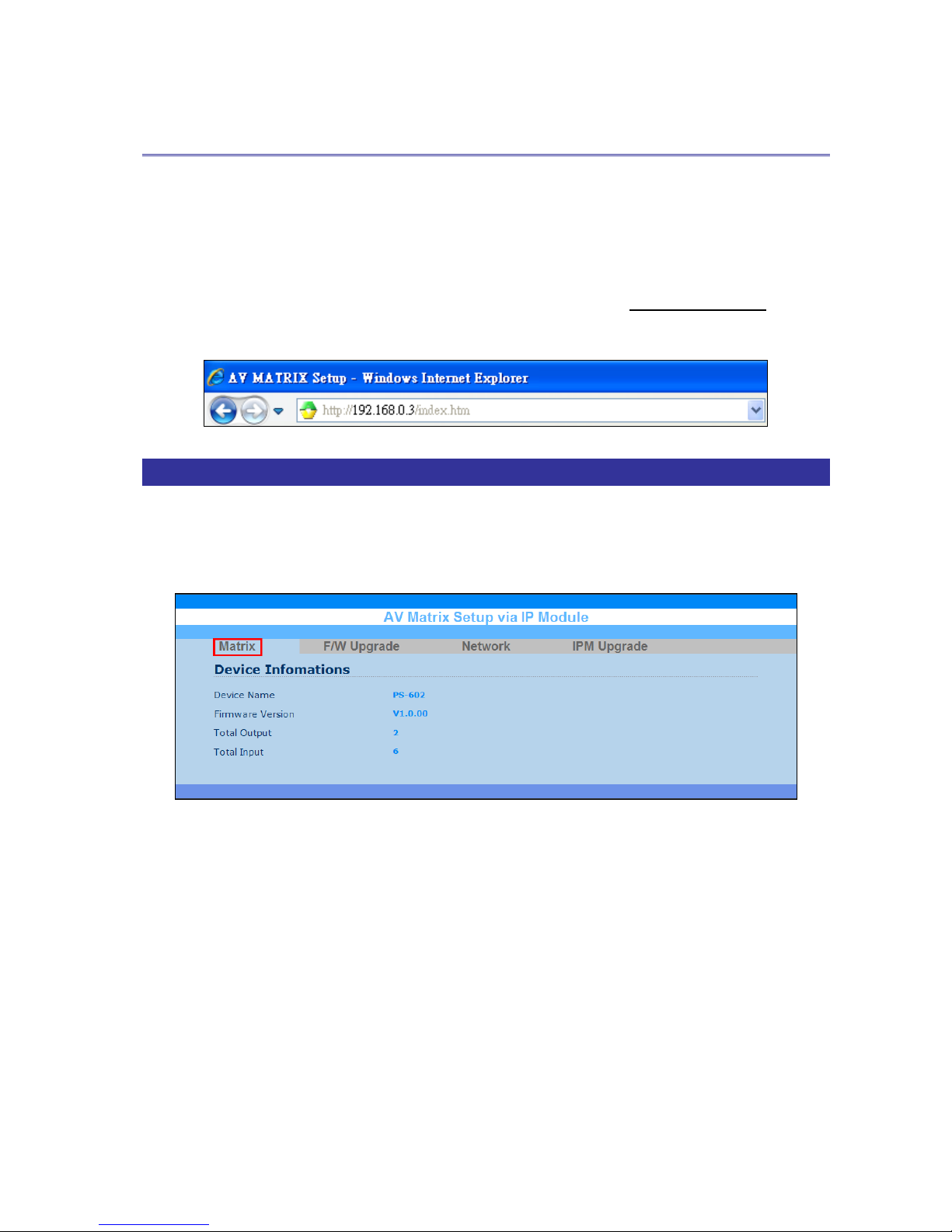
Open the Browser on your PC, key in the default IP address: http://192.168.0.3 to login
the AV MATRIX Setup configuration menu.
Matrix
Click “Matrix” to display the device information including Device Name, Firmware
Version, Total Output and Total Input. Then reboot your Switcher to take the new settings
effect and renew the information.
Page 56
V
V
V
P
P
P
-
-
-
6
6
6
0
0
0
2
2
2
H
H
H
H
H
H
T
T
T
U
U
U
55
F/W Upgrade
The Switcher allows you to upgrade firmware General, Module and Manual.
Besides, the firmware upgrade will not stop even though the web connection is fail
suddenly. Please check with the LCD screen to confirm the firmware upgrade has been
finished successfully or wait at least 2 minutes then power off to restart your PC.
General Upgrade
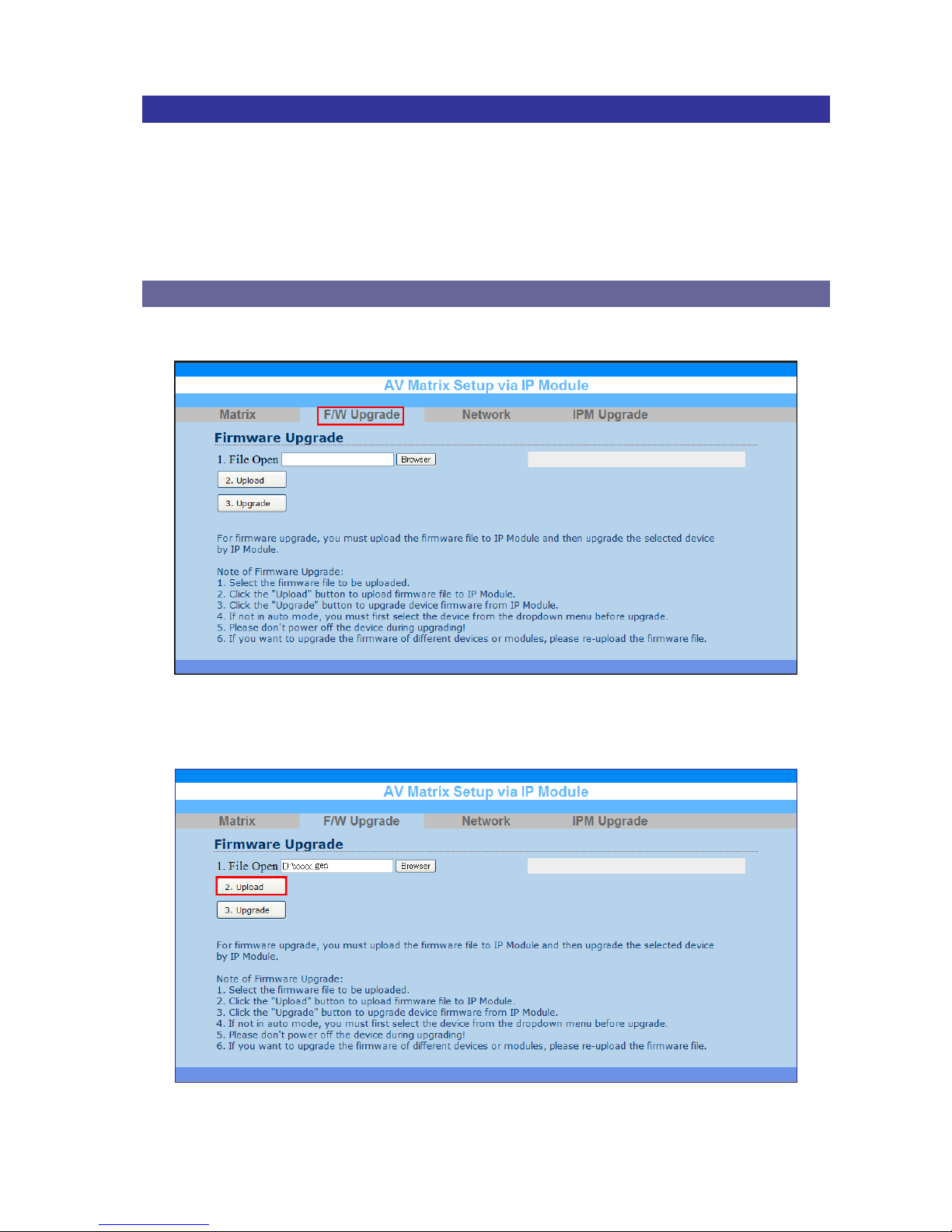
1. Click “F/W Upgrade” to enter the F/W Upgrade menu.
2. Click “Browser” to select upgraded .gen firmware, then click “Upload” to upload the
firmware to web server.
Page 57
V
V
V
P
P
P
-
-
-
6
6
6
0
0
0
2
2
2
H
H
H
H
H
H
T
T
T
U
U
U
56
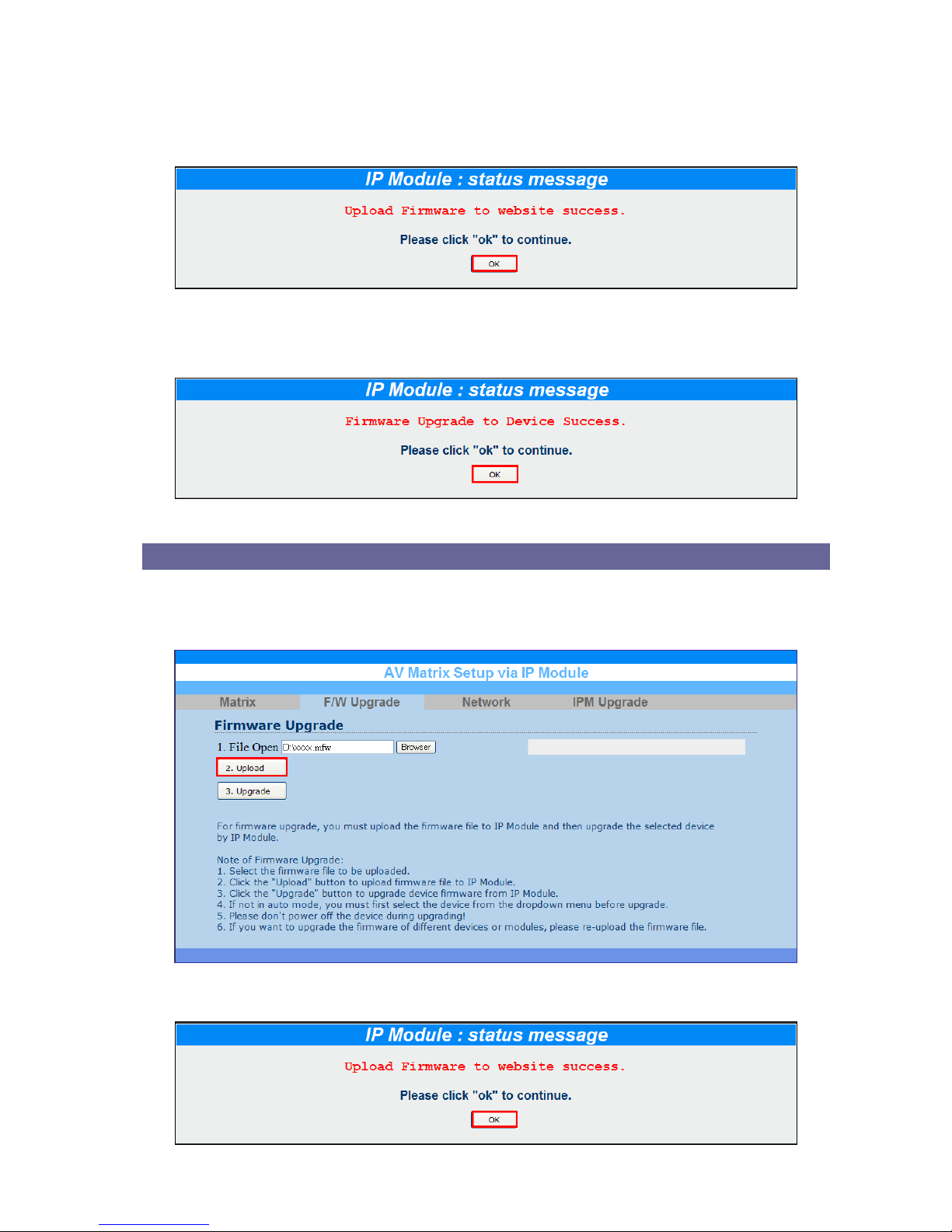
3. When the upload is successful, the following information will appear. Click “OK” to
continue.
4. Click “Upgrade” to upgrade. When the upgrade is successful, the following
information will appear, Click “OK” to complete the upgrade.
Module Upgrade
1. Click “F/W Upgrade” to enter the F/W Upgrade menu. Click “Browser” to select
upgraded .mfw firmware, then click “Upload” to upload the firmware to web server.
2. Click “OK” to continue.
Page 58
V
V
V
P
P
P
-
-
-
6
6
6
0
0
0
2
2
2
H
H
H
H
H
H
T
T
T
U
U
U
57
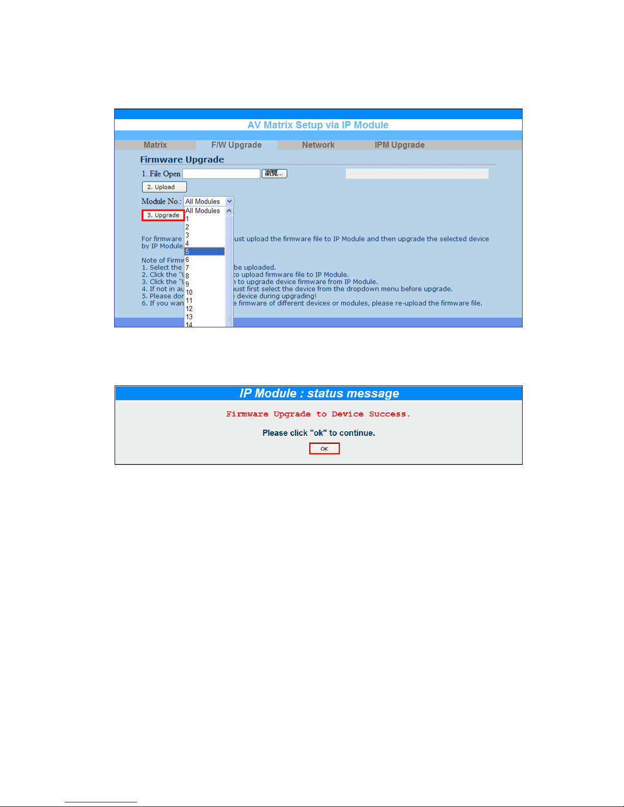
3. Select the suitable Module No. from the drop-down menu. Click “Upgrade” to
upgrade.
4. Click “Upgrade” to upgrade. When the upgrade is successful, the following
information will appear, Click “OK” to complete the upgrade.
Page 59
V
V
V
P
P
P
-
-
-
6
6
6
0
0
0
2
2
2
H
H
H
H
H
H
T
T
T
U
U
U
58
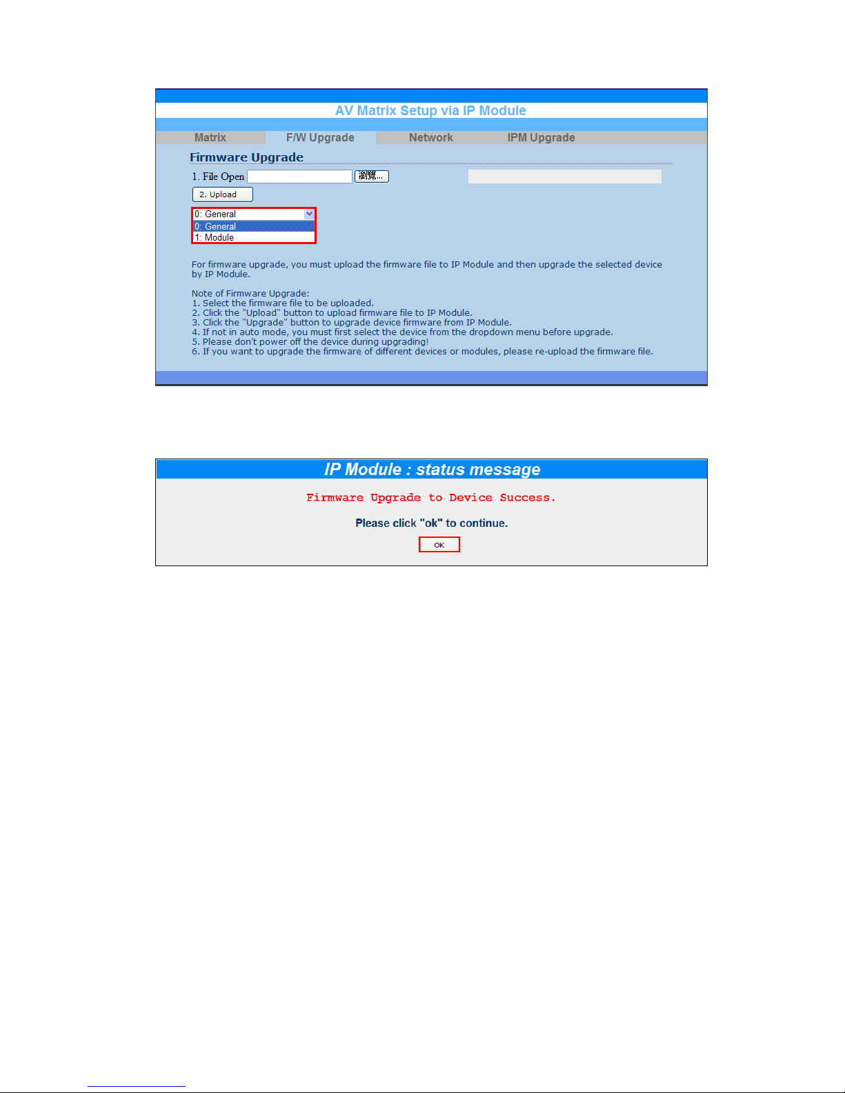
Manual Upgrade
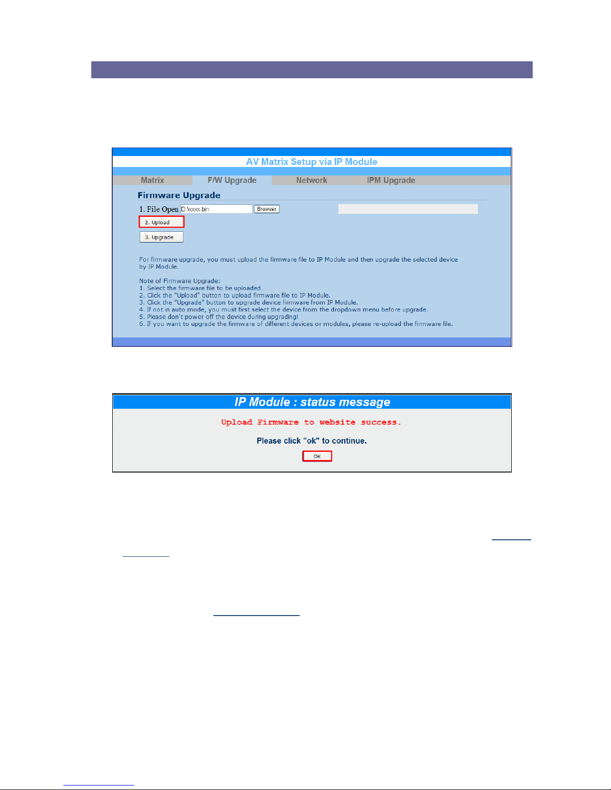
1. Click “F/W Upgrade” to enter the F/W Upgrade menu. Click “Browser” to select
upgraded .bin or .enc firmware, then click “Upload” to upload the firmware to web
server.
2. Click “OK” to continue.
3. Select the 0: General or 1: Module from the drop-down menu. Click “Upgrade” to
upgrade.
0: General: Select this item will hide the Module No. option. Refer to General
Upgrade.
1: Module: Select this item will allow you to upgrade the firmware of module; you
have to select the suitable Module No. from the drop-down list. Click “Upgrade” to
upgrade. Refer to Module Upgrade.
Page 60
V
V
V
P
P
P
-
-
-
6
6
6
0
0
0
2
2
2
H
H
H
H
H
H
T
T
T
U
U
U
59
4. Click “Upgrade” to upgrade. When the upgrade is successful, the following
information will appear, Click “OK” to complete the upgrade.
Page 61
V
V
V
P
P
P
-
-
-
6
6
6
0
0
0
2
2
2
H
H
H
H
H
H
T
T
T
U
U
U
60
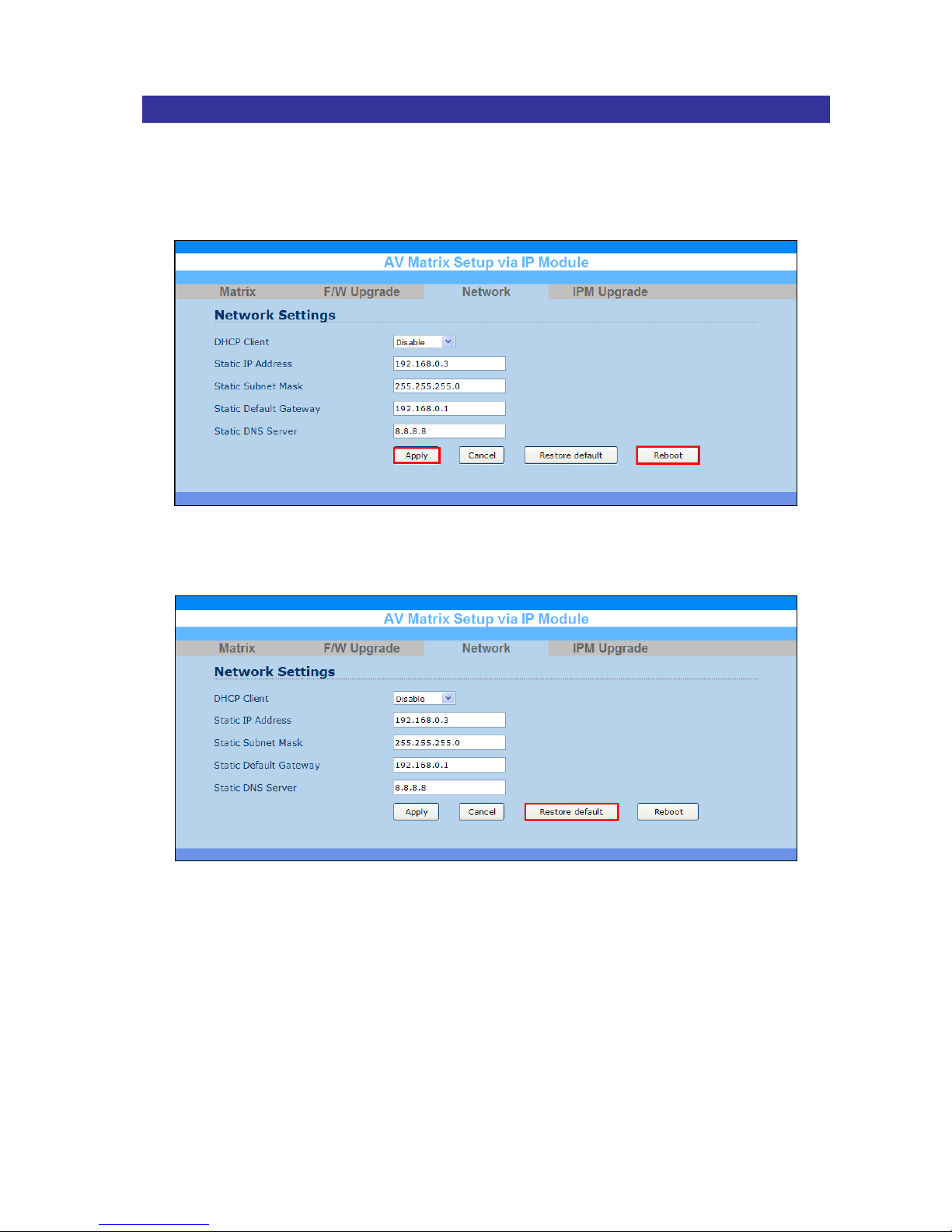
Network
1. Click “Network” to enter the Network Settings information menu. After renewing the
relative network settings, click “Apply” to save, and then click “Reboot” to take new
settings effect.
2. Or click “Restore default” to restore all settings to the factory default values.
Page 62
V
V
V
P
P
P
-
-
-
6
6
6
0
0
0
2
2
2
H
H
H
H
H
H
T
T
T
U
U
U
61
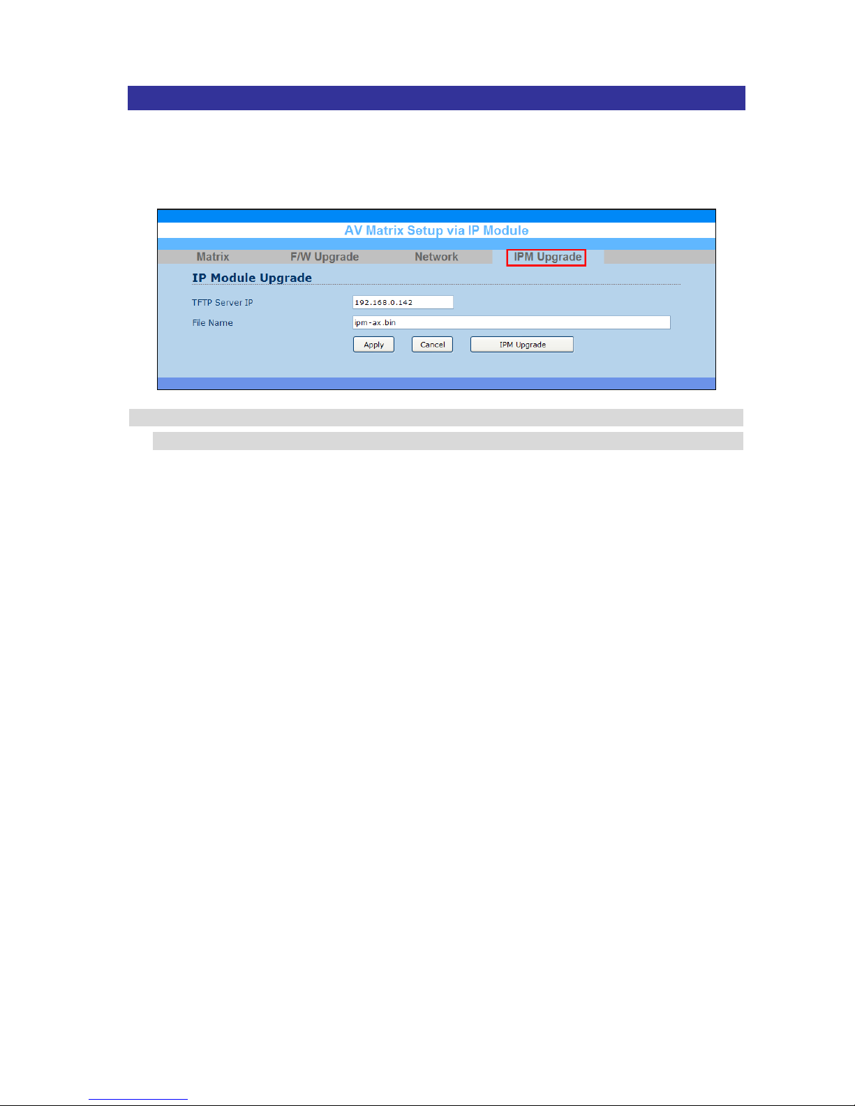
IPM Upgrade
Click “Upgrade” to enter the IP Module Upgrade menu. Enter the TFTP Server IP and
upgrade File Name, click “Apply” to save and then click “IPM Upgrade” to take the
settings effect.
Before upgrading the IP module, you can use the existed TFTP Server or set up a
TFTP Server by yourself to put the Firmware file on. Then, enable your TFTP Server.
 Loading...