

Page 1

Application Note - Video Sync Setup
(For VS-700) | Version 1.3
Page 2

Table of Contents
1 Network Topology ................................................................................................... 3
2 Installation ............................................................................................................... 4
2.1 Connecting Master unit to LAN ........................................................................... 4
2.2 Connecting Slave unit(s) to LAN ......................................................................... 4
2.3 Connecting Slave unit(s) to monitor(s) ............................................................... 4
3 NETCFG.INI and DVSYNC.INI setup ..................................................................... 6
3.1 Configure a NETCFG.INI for master unit ............................................................ 6
3.2 Configure a NETCFG.INI for slave unit ............................................................... 7
3.3 Disable the DVSYNC.INI .................................................................................... 8
4 Playlist Setup .......................................................................................................... 9
4.1 Playlist for Master Player .................................................................................... 9
4.2 Playlist for Slave Player .................................................................................... 12
Page 3
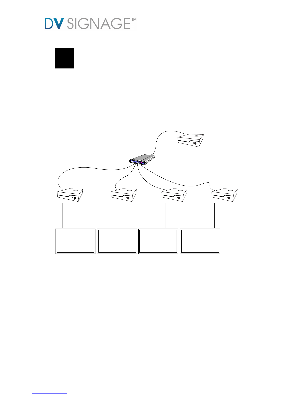
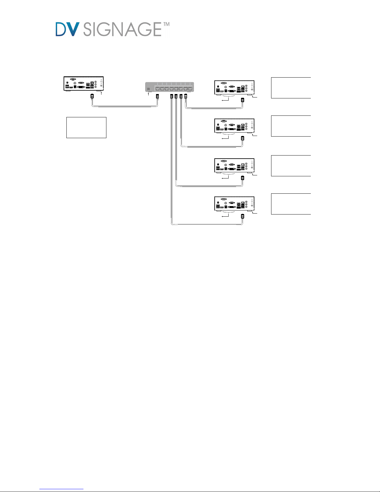
1 Network Topology
This setup is designed to achieve a video synchronization over Ethernet connection.
It requires one Master unit to control all slave units as a result to sync the video on
the monitors at the same time.
Both Master and Slave unit are required to assign a dedicated IP address (i.e. static
IP)
DIGITAL VIEW
Switch
VS-700(Master)
Static IP (e.g. 10.1.0.70)
RJ-45
RJ-45
RJ-45
RJ-45
RJ-45
VS-700
(Slave)
Static IP
(e.g.10.1.0.71)
VS-700
(Slave)
Static IP
(e.g.10.1.0.72)
VS-700
(Slave)
Static IP
(e.g.10.1.0.73)
VS-700
(Slave)
Static IP
(e.g.10.1.0.74)
Page 4
2 Installation
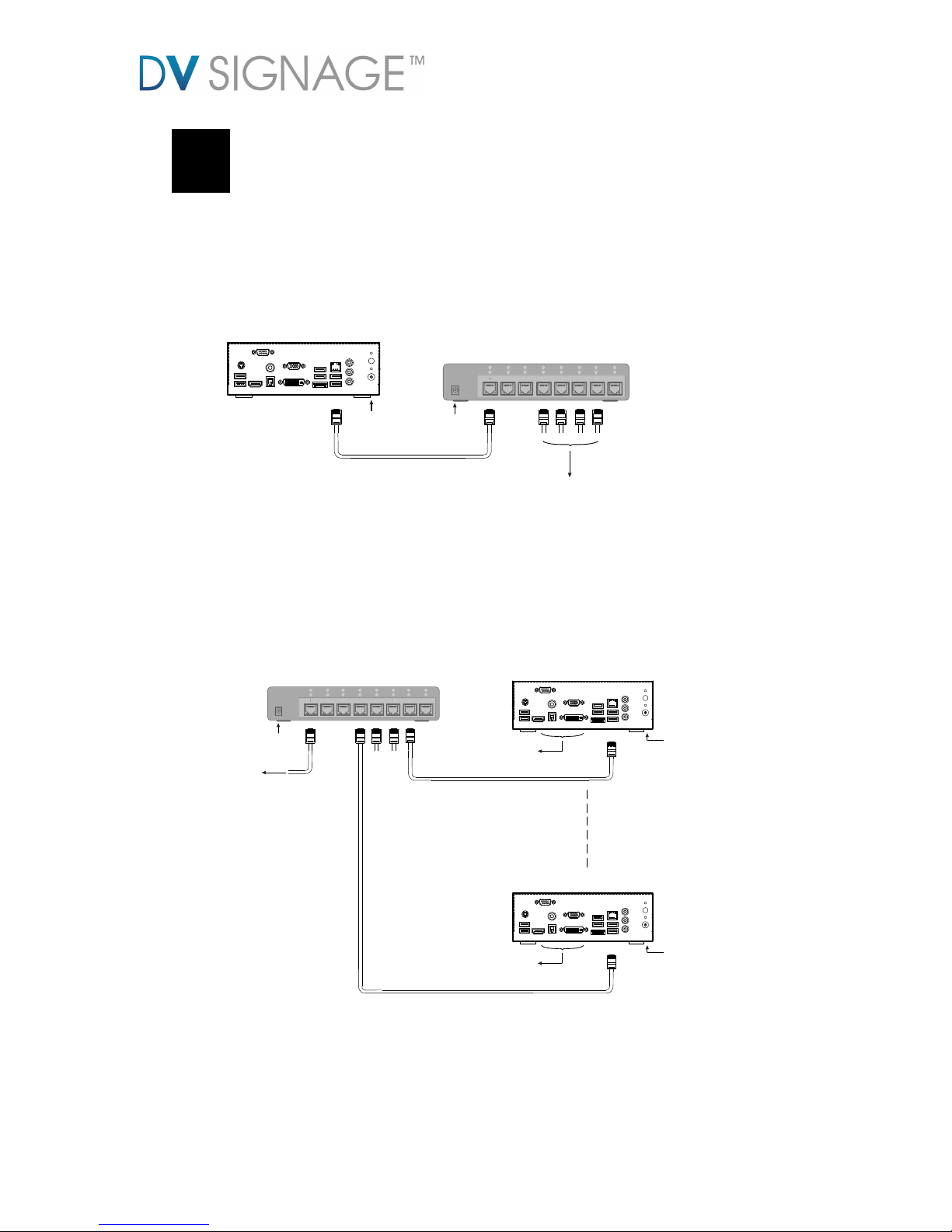
2.1 Connecting Master unit to LAN
Connect the Master unit (VS-700) to the network switch with a standard Cat-5
Ethernet cable (Straight type cable).
Connecting to Slave units
RJ-45 (Straight cable)
Network switch
1 2 3 4 5 6 7 8
356
8
100M
LNK /ACT
Power Supply
RS-232
SPDIF
PS/2
DC 19V
USB USB
USB
HDMI
VGA
DVI
LAN
eSATA
Line in
Line out
Mic
Master unit (VS-700)
Power Supply
2.2 Connecting Slave unit(s) to LAN
Connect the Slave unit(s) (VS-700) to the network switch with a standard Cat-5
Ethernet cable (Straight type cable).
RJ-45 (Straight cable)
Network switch
1 2 3 4 5 6 7 8
356
8
100M
LNK /ACT
Power Supply
Power Supply
Connect to Monitor
Connecting to Master unit
RS-232
SPDIF
PS/2
DC 19V
USB USB
USB
HDMI
VGA
DVI
LAN
eSATA
Line in
Line out
Mic
Slave unit (VS-700)
RJ-45 (Straight cable)
Power Supply
Connect to Monitor
RS-232
SPDIF
PS/2
DC 19V
USB USB
USB
HDMI
VGA
DVI
LAN
eSATA
Line in
Line out
Mic
Slave unit (VS-700)
2.3 Connecting Slave unit(s) to monitor(s)
Page 5
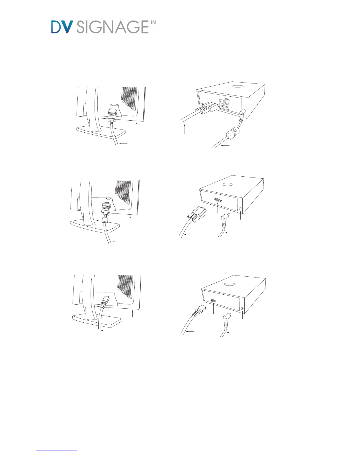
Connect all Slave units (VS-700) to the monitor. Make sure you got the proper video
output setting (Default output is 1920x1080 resolution) to match with your LCD
monitor.
VGA cable
VGA Monitor
(Support 1920x1080
or 1280x720)
DVI
cable
Power cable
HDMI
HDMI cable
DC 19V in
Power cable
VGA cable
VGA
DC 19V in
Power cable
DVI cable
DVI Monitor
(Support 1920x1080
or 1280x720)
HDMI cable
HDMI Monitor
(Support 1920x1080
or 1280x720)
DVI connection
VGA connection
HDMI connection
Page 6

3 NETCFG.INI and DVSYNC.INI setup
To enable video synchronization feature on VS-700, a special options are required to setup in
NETCFG.INI file. Below is the section to show how to configure a NETCFG.INI for master unit
and slave unit respectively.
3.1 Configure a NETCFG.INI for master unit
Copy all video content on to “media” folder on USB flash drive.
Create a NETCFG.INI and place it in the “media” folder on the USB flash drive.
Update the video content and NETCFG.INI on to the Master unit (VS-700) through
USB update. (see VS-700 user guide)
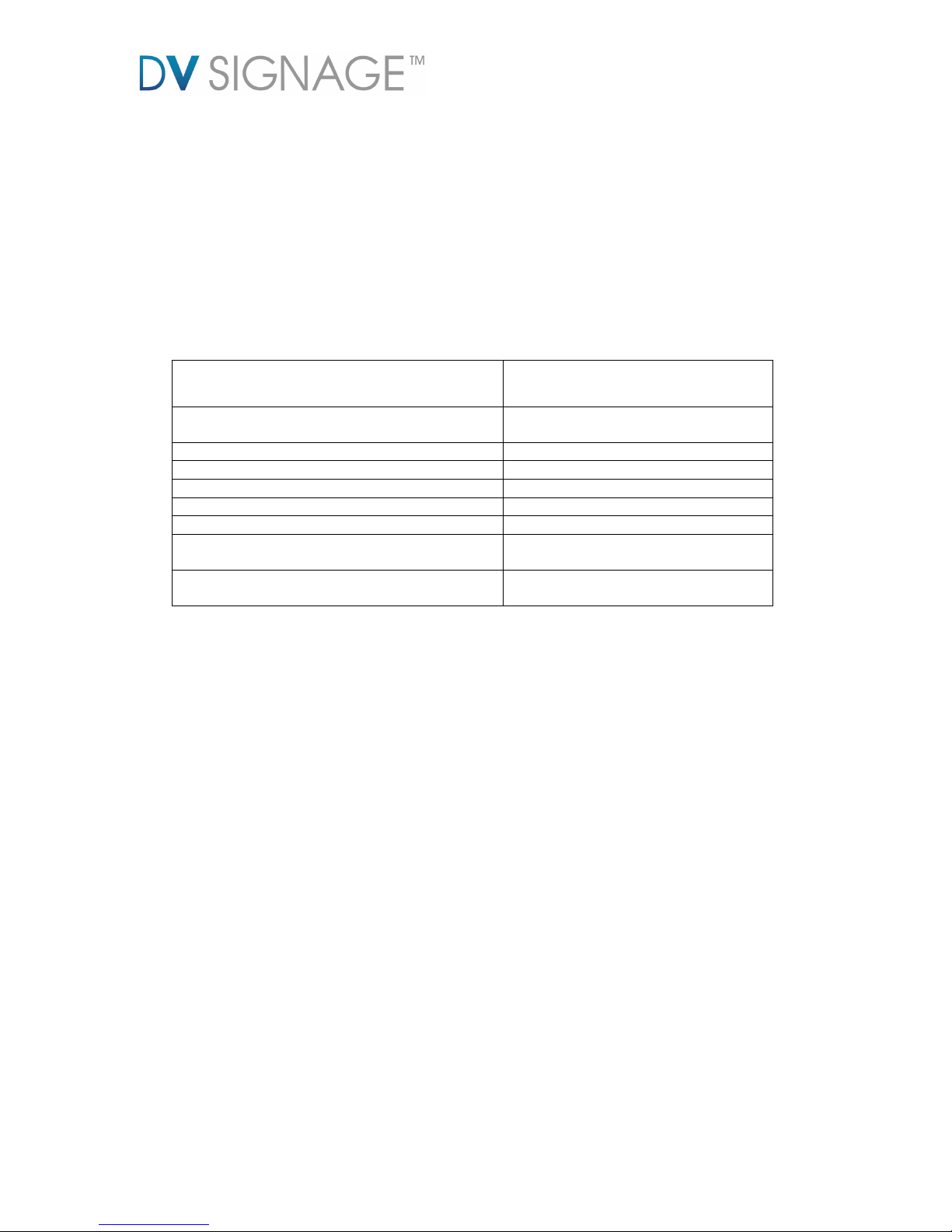
The NETCFG.INI file contains some system and network settings. The following table
shows the major options required in Video synchronization.
Options in NETCFG.INI
Description
IP_OVERWRITE
0 – Keep old IP address
1 – Use the new IP address
IP
IP address
NETMASK
Subnet Mask Address
GATEWAY
Gateway address
DNS1
DNS1 address
DNS2
DNS2 address
NETSYNC_MASTER_MODE
Master mode enable
(0=disable, 1=enable)
NETSYNC_NUM_SLAVE
The total number of Slave unit in the
LAN.
Below is an example of a NETCFG.INI file for “Master unit”:
IP_OVERWRITE=1
IP=10.1.0.70
NETMASK=255.255.255.0
GATEWAY=10.1.0.1
NETSYNC_MASTER_MODE=1
NETSYNC_NUM_SLAVE=4
Note: All master and slave unit must in different static IP addresses.
Page 7
3.2 Configure a NETCFG.INI for slave unit
Copy all video content on to “media” folder on USB flash drive.
Create a NETCFG.INI and place it in the “media” folder on the USB flash drive.
Update the video content and NETCFG.INI on to the Slave unit (VS-700) through
USB update. (see VS-700 user guide)
The NETCFG.INI file contains some system and network settings. The following table
shows the major options required in Video synchronization.
Options in NETCFG.INI
Description
IP_OVERWRITE
0 – Keep old IP address
1 – Use the new IP address
IP
IP address
NETMASK
Subnet Mask Address
GATEWAY
Gateway address
DNS1
DNS1 address
DNS2
DNS2 address
NETSYNC_SLAVE_MODE
Slave mode enable
(0=disable, 1=enable)
NETSYNC_MASTER_ADDR
An IP address of Master unit
Below is an example of a NETCFG.INI file for “Slave unit”:
IP_OVERWRITE=1
IP=10.1.0.71
NETMASK=255.255.255.0
GATEWAY=10.1.0.1
NETSYNC_SLAVE_MODE=1
NETSYNC_MASTER_ADDR=10.1.0.70
Note: All master and slave unit must in different static IP addresses.
Both master and slave unit must contain the same content (but different in playlist
settings – see Section 4).
Page 8
A complete NETCFG.INI example for Master and Slave units:
RJ-45 (Straight cable)
RJ-45 (Straight cable)
RJ-45 (Straight cable)
Network switch
NETCFG.INI (for Slave unit)
NETCFG.INI (for Master unit)
1 2 3 4 5 6 7 8
356
8
100M
LNK /ACT
Power Supply
Power Supply
RS-232
SPDIF
PS/2
DC 19V
USB USB
USB
HDMI
VGA
DVI
LAN
eSATA
Line in
Line out
Mic
Master unit (VS-700)
Power Supply
Power Supply
Connect to Monitor
RS-232
SPDIF
PS/2
DC 19V
USB USB
USB
HDMI
VGA
DVI
LAN
eSATA
Line in
Line out
Mic
Slave unit (VS-700)
Connect to Monitor
RS-232
SPDIF
PS/2
DC 19V
USB USB
USB
HDMI
VGA
DVI
LAN
eSATA
Line in
Line out
Mic
Slave unit (VS-700)
RJ-45 (Straight cable)
RJ-45 (Straight cable)
Power Supply
Connect to Monitor
RS-232
SPDIF
PS/2
DC 19V
USB USB
USB
HDMI
VGA
DVI
LAN
eSATA
Line in
Line out
Mic
Slave unit (VS-700)
Power Supply
Connect to Monitor
RS-232
SPDIF
PS/2
DC 19V
USB USB
USB
HDMI
VGA
DVI
LAN
eSATA
Line in
Line out
Mic
Slave unit (VS-700)
IP=10.1.0.71
NETMASK=255.255.255.0
GATEWAY=10.1.0.1
DNS1=0.0.0.0
DNS2=0.0.0.0
NETSYNC_SLAVE_MODE=1
NETSYNC_MASTER_ADDR=10.1.0.70
NETCFG.INI (for Slave unit)
IP_OVERWRITE=1
IP=10.1.0.72
NETMASK=255.255.255.0
GATEWAY=10.1.0.1
DNS1=0.0.0.0
DNS2=0.0.0.0
NETSYNC_SLAVE_MODE=1
NETSYNC_MASTER_ADDR=10.1.0.70
NETCFG.INI (for Slave unit)
IP_OVERWRITE=1
IP=10.1.0.73
NETMASK=255.255.255.0
GATEWAY=10.1.0.1
DNS1=0.0.0.0
DNS2=0.0.0.0
NETSYNC_SLAVE_MODE=1
NETSYNC_MASTER_ADDR=10.1.0.70
NETCFG.INI (for Slave unit)
IP_OVERWRITE=1
IP=10.1.0.74
NETMASK=255.255.255.0
GATEWAY=10.1.0.1
DNS1=0.0.0.0
DNS2=0.0.0.0
NETSYNC_SLAVE_MODE=1
NETSYNC_MASTER_ADDR=10.1.0.70
IP_OVERWRITE=1
IP=10.1.0.70
NETMASK=255.255.255.0
GATEWAY=10.1.0.1
DNS1=0.0.0.0
DNS2=0.0.0.0
NETSYNC_MASTER_MODE=1
NETSYNC_NUM_SLAVE=4
3.3 Disable the DVSYNC.INI
All VS-700 are shipped with “DVSYNC.INI” disable setting. If this DVSYNC.INI was
enabled, the video sync among master and slaves might not successful.
In case you find the slaves units cannot video sync with each others, please try to
disable the dvsync.ini through the following procedures.
1. Create a dummy DVSYNC.INI (i.e. a blank file) and place it in the “media” folder
on the USB flash drive.
2. Update the dummy DVSYNC.INI on to the Master unit (VS-700) and all Slave unit
(VS-700) through USB update. (see VS-700 user guide)
Page 9
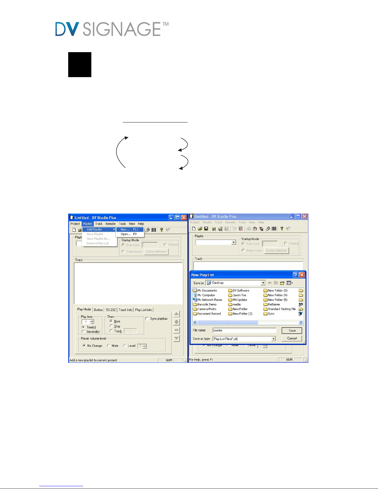
4 Playlist Setup
Players must have a suitably setup playlist as outlined below.
4.1 Playlist for Master Player
Track 1 (1.mpg)
Track 2 (2.mpg)
Track 3 (3.mpg)
Next Track
Playlist settings for Master
Next Track
Next Track
Step 1: Open DV Studio – the Digital View playlist creation software.
Step 2: Add a new playlist.
Page 10
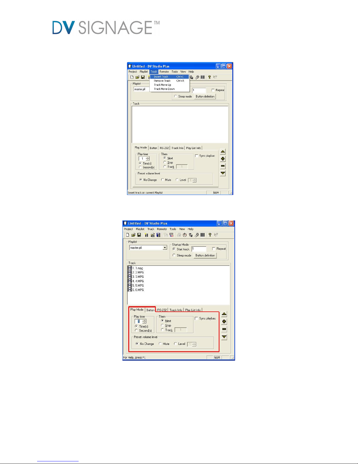
Step 3: Insert the media file to the playlist.
Step 4: Set the play mode and button.
Page 11
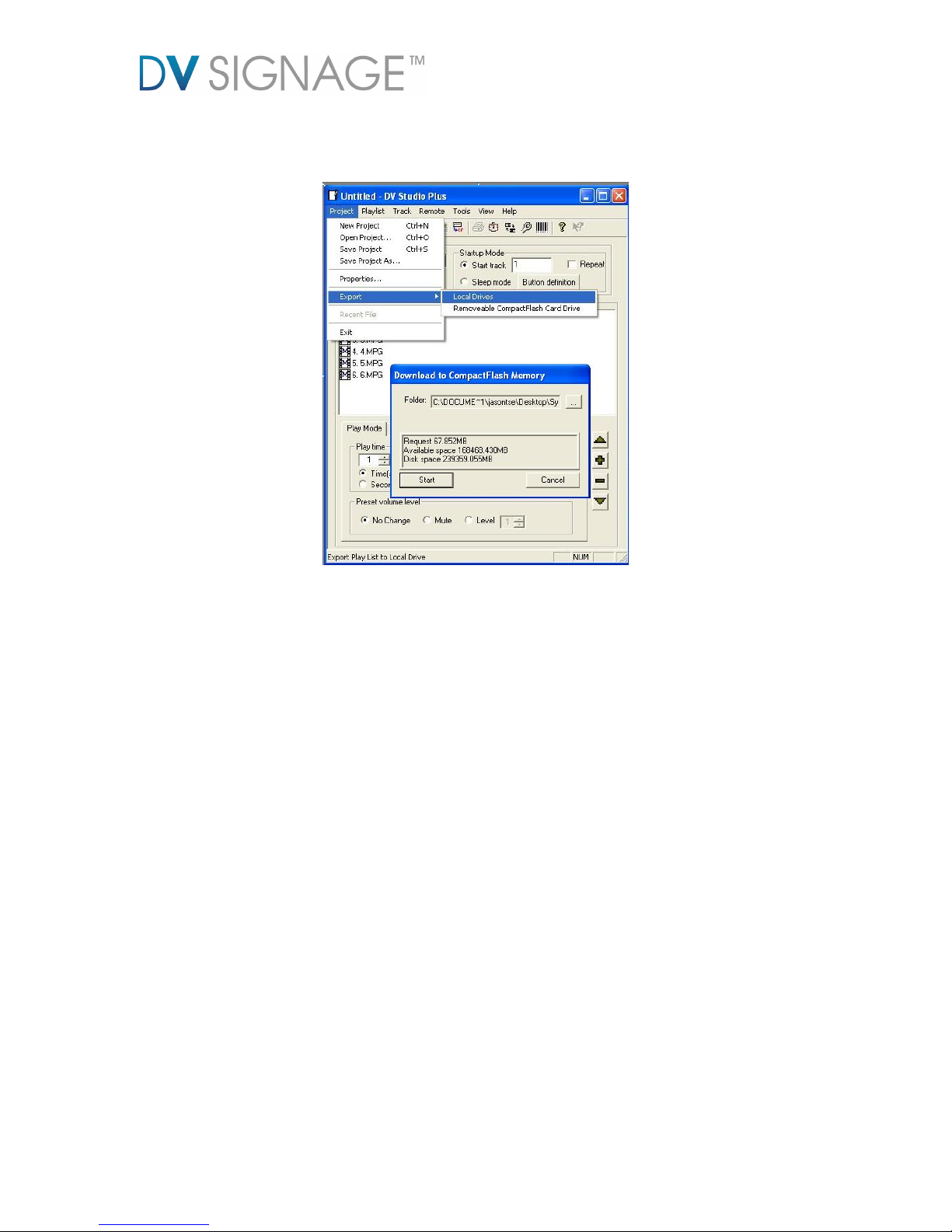
Step 5: Click Project -> Export to export the playlist file.
Page 12
4.2 Playlist for Slave Player
Track 1 (1.mpg)
Track 2 (2.mpg)
Track 3 (3.mpg)
Stop
Playlist settings for Slave
Stop
Stop
Step 1: Open the DV studio.
Step 2: Add a new playlist. (same as Section 2.3.1 – step 2)
Step 3: Insert the media file to the playlist. (same as Section 2.3.1 – step 3)
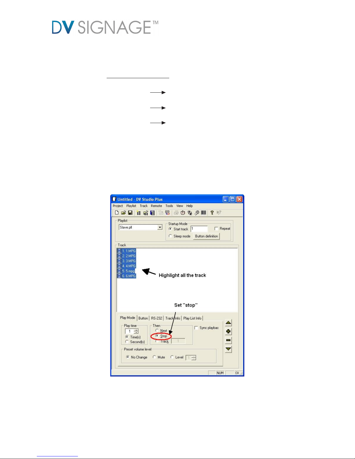
Step 4: Highlight all the track and set “Stop” in the Play Mode.
Page 13
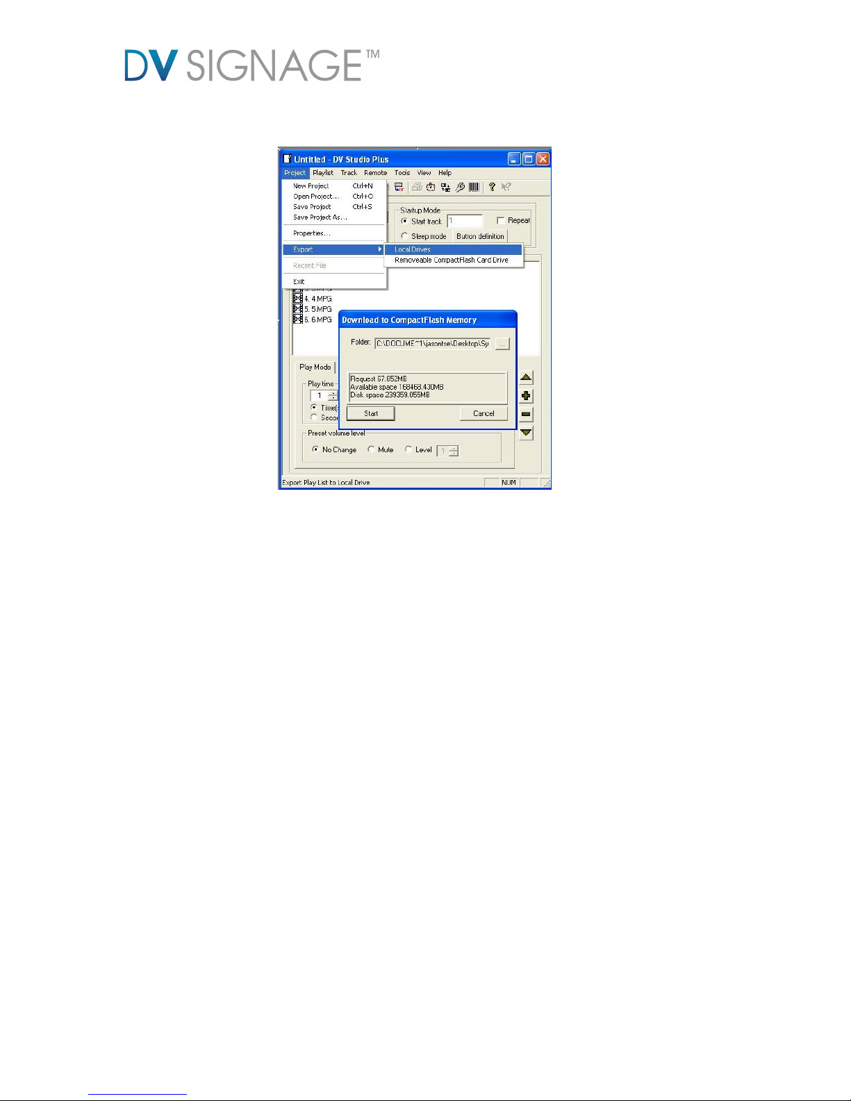
Step 5: After finished the step 4, click Project -> Export to export the playlist file.
[END]
Page 14

CONTACT DETAILS
USA: 18440 Technology Drive
Building 130
Morgan Hill, CA 95037
EUROPE: The Lake House,
Knebworth Park,
Hertfordshire, SG3 6PY
UK
ASIA: 16th floor Millennium City 3
370 Kwun Tong Road
Kwun Tong
Hong Kong
Specifications subject to change without notice
Application Note – Video Sync Setup on VS-700 (June 1 2011) © DV Signage 2012
 Loading...