

Page 1
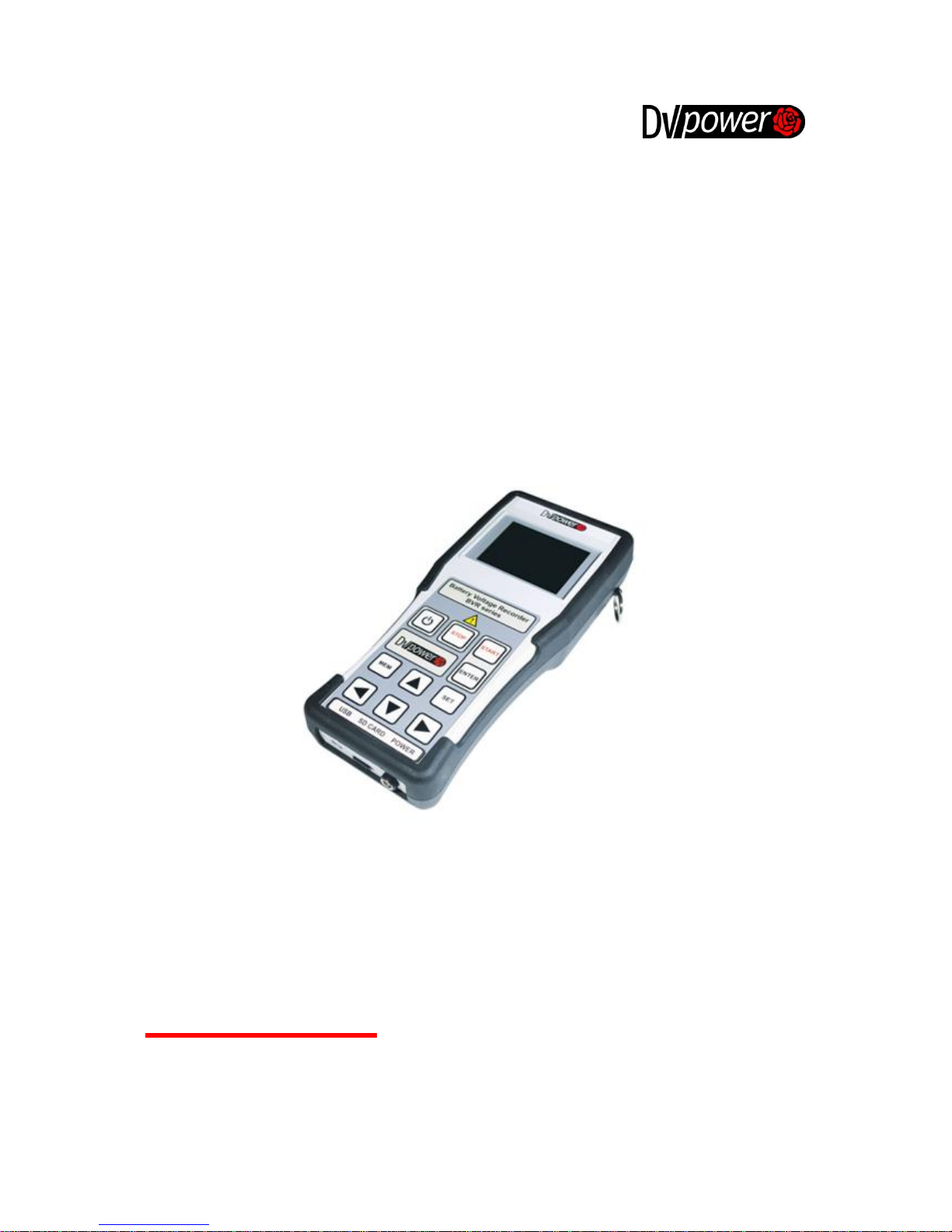
BATTERY VOLTAGE RECORDER
BVR11
Manual
Manual Version: M-B011VR-202-EN
This Manual refers to the firmware version 1.14
Publishing date: 2016-08-08
Page 2

Battery Voltage Recorder BVR11
M-B011VR-202-EN 2
Contents
1. Introduction ....................................................................................................................................... 3
1.1. SAFETY INSTRUCTIONS ............................................................................................................... 3
1.1.1. Terms of Use......................................................................................................................... 3
1.1.2. Orderly Practices and Procedures ......................................................................................... 3
1.1.3. Instrument Maintenance ........................................................................................................ 3
1.1.4. Operator‟s Qualifications ................................................................................................ ....... 3
1.1.5. Safe Operating Procedures ................................................................................................... 4
1.1.6. PC Interface .......................................................................................................................... 4
1.2. INTENDED USE ........................................................................................................................... 4
2. Description ........................................................................................................................................ 5
2.1. FRONT PANEL COMPONENTS ....................................................................................................... 5
3. Getting Started ................................................................................................................................. 7
3.1. CONNECTING BVR11 TO A TEST OBJECT ..................................................................................... 7
3.2. SETTING MEASUREMENT PARAMETERS ........................................................................................ 8
3.2.1. Main Menu ............................................................................................................................ 8
3.2.2. Measurement Menu .............................................................................................................. 9
3.2.3. Memory Menu ..................................................................................................................... 11
3.2.4. Settings Menu ..................................................................................................................... 12
4. SD Card Initialization Error Messages ............................................................................................ 16
4.1. INITIALIZATION FAILURE DURING STARTUP OF THE BVR11 ........................................................... 16
4.2. INITIALIZATION FAILURE IN MEASUREMENT MENU ........................................................................ 16
5. Troubleshooting .............................................................................................................................. 17
MEASUREMENT PARAMETERS ............................................................................................................... 17
5.1. CHECKING VOLTAGE MEASUREMENT ACCURACY ................................................................ ......... 17
6. Customer Service ........................................................................................................................... 18
7. Packing the Instrument for Shipment .............................................................................................. 19
8. Technical Data ................................................................................................................................ 20
9. Accessories .................................................................................................................................... 22
Manufacturer Contact Information .......................................................................................................... 23
Page 3

Battery Voltage Recorder BVR11
M-B011VR-202-EN 3
1. Introduction
The purpose of this Manual is to provide helpful instructions on how to use the BVR11 instrument safely,
properly and efficiently.
The following instructions will help the user to avoid unsafe situations, reduce maintenance costs and will
ensure the reliability and durability of the BVR11 instrument.
BVR11 must be used in accordance with all existing safety requirements and regulations based on
national/local standards for accident prevention and environmental protection. In addition, the relevant
international standards are listed in paragraph 8 of the “Technical data” section of this document.
1.1. Safety Instructions
Safety is the responsibility of the user. Before operating the BVR11, please read the following safety
instructions carefully.
It is not recommended that the BVR11 is used (or even turned on) without careful observation of the
instructions listed in this Manual. The BVR11 should only be operated by trained and authorized
personnel.
1.1.1. Terms of Use
The BVR11 shall be used only if it is in good technical condition. Its use shall be in accordance with
local safety and industrial regulations. Adequate precautions must be taken to avoid any risks related
to high voltages associated with this equipment and nearby objects.
The BVR11is intended exclusively for the application purposes specified in the ”Intended Use” section.
The manufacturer and distributors are not liable for any damage resulting from wrong usage. The user
bears responsibility in case of not following the instructions defined in this document.
Do not remove the protective casing of BVR11.
All service and maintenance work must be performed by qualified personnel only.
1.1.2. Orderly Practices and Procedures
The Manual shall always be available on the site where the BVR11 is used.
Before using BVR11, all personnel (even personnel who only occasionally, or less frequently, work
with BVR11) assigned to operate the BVR11 should read this Manual.
Do not make any modifications, extensions, or adaptations to the BVR11.
Use the BVR11 only with the original accessories provided by its manufacturer.
Use the BVR11 and its original accessories for the device‟s intended use only.
1.1.3. Instrument Maintenance
The device should be kept clean in order to prevent excessive cases of dust or other contaminants
affecting its operation. It should be cleaned with water/isopropyl alcohol after any dirt/contaminants are
noticed on its surfaces.
1.1.4. Operator’s Qualifications
Testing with the BVR11 should only be carried out by authorized and qualified personnel.
Personnel receiving training, instruction or education on the BVR11 should remain under the constant
supervision of an experienced operator while working with the test set and the test object.
Page 4

Battery Voltage Recorder BVR11
M-B011VR-202-EN 4
1.1.5. Safe Operating Procedures
Before putting the BVR11 into operation, check the test set for any visible damage.
Do not operate the BVR11 under wet or moist conditions (condensation).
Do not operate the BVR11 if explosive gas or vapors are present.
Removing the BVR11 protective casing will void the warranty. Any work inside the instrument without
prior authorization from DV Power will also void the warranty.
If the BVR11 seems to be malfunctioning, please contact the DV Power Support Team (refer to the
"Manufacturer Contact Information” section) after previously checking the “Error Messages” section.
1.1.6. PC Interface
The BVR11 is provided with a mini USB cable for USB communication with a PC. Bluetooth
communication is available as well, with a Bluetooth communication module (dongle) as the recommended
accessory.
In case the Bluetooth cannot establish a communication with DV-B Win software, please follow the
procedure below:
• Disconnect the Bluetooth communication module (dongle) from a PC
• Turn off the BVR11
• Turn on the BVR11
• Reconnect the Bluetooth communication module
• Check the connection by starting DV-B Win software
1.2. Intended Use
Battery Voltage Recorder (BVR11) is a portable, handheld device for measuring battery voltages, ambient
temperature, and float current while battery is either in online or offline mode. It is used on batteries and
large battery banks that serve as a backup power supply in:
• Power plants
• Generator excitation systems
• Substations
• Protection and control systems.
The BVR11 can be used as an individual device, and also in a combination with the BLU series of devices.
In this case, the BVR11 serves as an efficient support tool for a battery capacity testing process, offering
cell voltage and ambient temperature measurement during the discharge process.
Page 5
Battery Voltage Recorder BVR11
M-B011VR-202-EN 5
2. Description
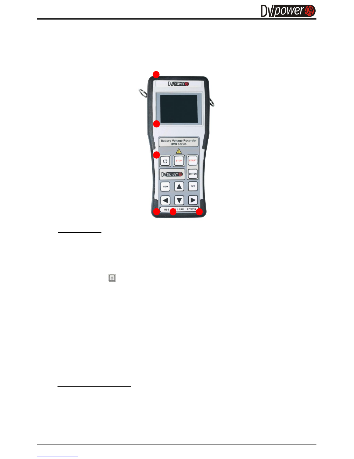
2.1. Front Panel Components
1. Operator Control
3,1„‟ color display
Displays the settings during the device test mode selection as well as the measured values during
and after a test operation.
2. Keyboard
Used to control the device.
• Use the button to turn on/off the device.
• Use the START button to start the test.
• Use the STOP button to stop a test.
• Use the ENTER button to confirm the defined test parameters, language, time and date, limits as
well as to go to the next screen if no changes needed on the active one. ENTER button is also
used for navigating to the Voltmeter mode or Current probe mode of measurement in Main
Menu.
• Use the LEFT/RIGHT buttons to navigate through the active menu.
• Use the UP/DOWN buttons to set the test parameters and to navigate through the Measurement
(MEM) and Settings (SET) Menu.
• Use the MEM button to go to the Memory Menu.
• Use the SET button to go to the Settings Menu (language, time & date, limits, default setup).
3. Voltage terminals
Voltage sense cable terminal
The terminal for connecting voltage sense cables or current clams used for float current
measurements.
2 3 4
5
Figure 2-1:
BVR11 Front Panel
1
Page 6
Battery Voltage Recorder BVR11
M-B011VR-202-EN 6
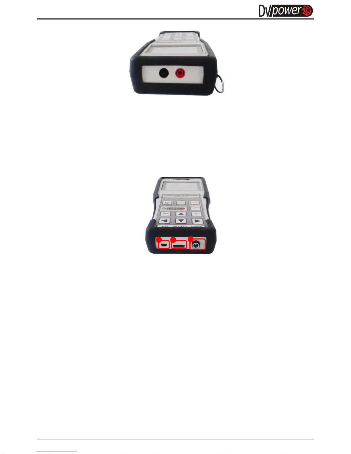
4. Interface
The BVR11 is equipped with a Bluetooth and USB serial interface to connect to an external computer,
if required.
5. SD Card
To store the test results the BVR11 is equipped with a removable 2 GB Mini SD Card.
6. Mains Power Connector
The connector for the mains power supply.
Figure 2-2:
Voltage sense terminals
Figure 2-3:
Mains power supply connector
4
5
6
Page 7
Battery Voltage Recorder BVR11
M-B011VR-202-EN 7
3. Getting Started
3.1. Connecting BVR11 to a Test Object
Before the BVR11 has been connected to a test object (e.g. a battery), the following steps must be taken:
• The test object should be examined in case of any visual damages or leakages.
Note: Always connect measuring cables to the BVR11 instrument first and then to the test object. When
disconnecting, always disconnect the cables from the test object first and then from the BVR11.
Not following these instructions may cause hazardous situations.
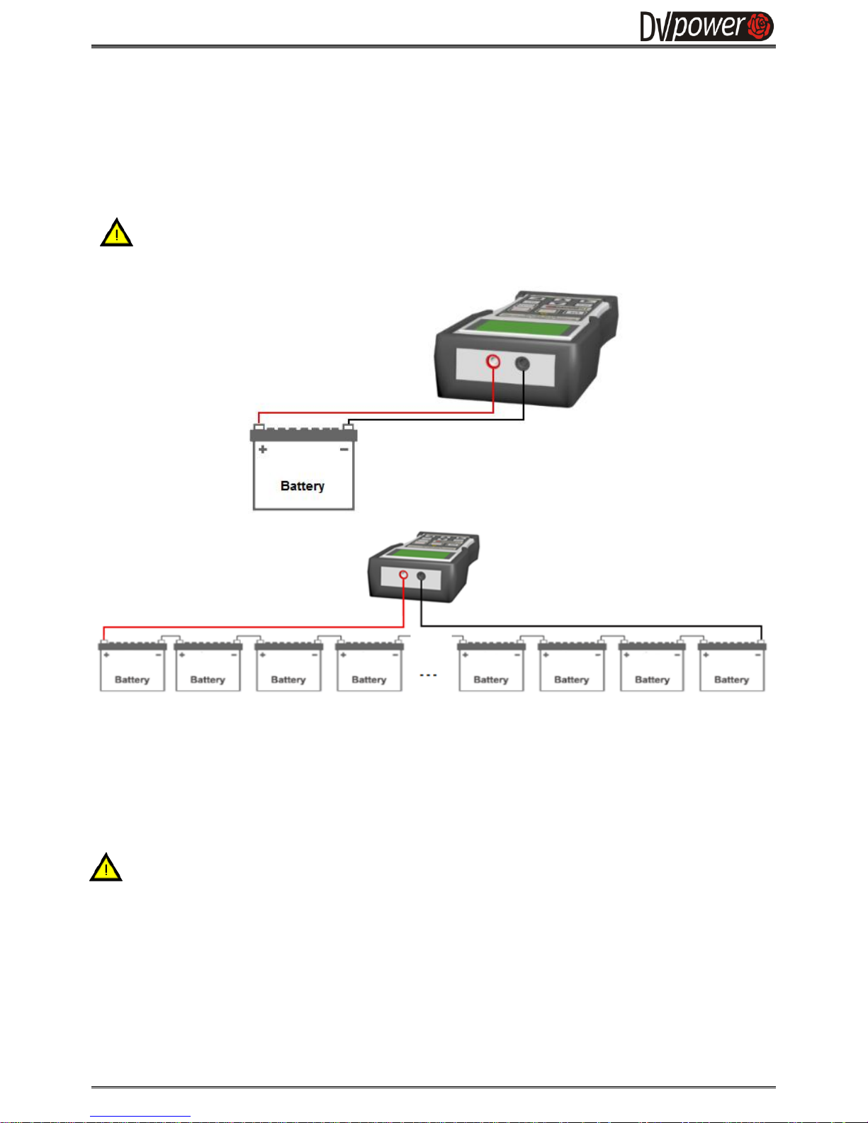
The red sense cable should be connected to the positive polarity side at the beginning of a battery or a cell
string, depending on a test object being measured. The black sense cable should be connected to the
negative polarity side at the end of the measured string (batteries or cells).
Any source of interference should be eliminated from the test area, if possible.
• To maximize the accuracy and measurement repeatability, make sure that all clamps have a good
connection to the test object and avoid any crossing between the measuring cables.
C A U T I O N
For safety reasons, a connection of the device should be always established with the test
object in the way described in this Manual.
The measuring cables should not be connected after the start of the test.
The measuring cables should not be disconnected before the test is over.
Figure 3-1:
Connecting BVR11 to a
single battery
Figure 3-2:
String measurement
with BVR11
Page 8
Battery Voltage Recorder BVR11
M-B011VR-202-EN 8
3.2. Setting Measurement Parameters
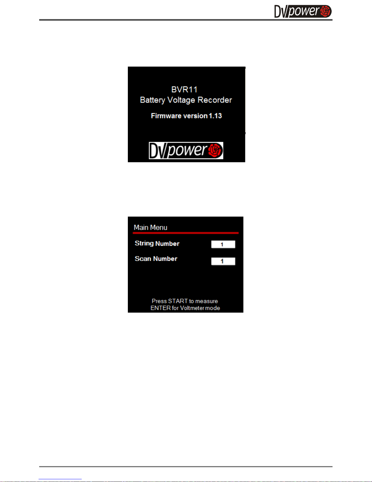
The Start message appearing on the BVR11 screen after turning on the device is shown in the Fig. 3-3.
3.2.1. Main Menu
Immediately following the first (initial) message on the display shown in the Figure 3-2, the BVR11
automatically changes the display to the Main Menu.
In the Main Menu, the following parameters need to be selected:
• String Number- This number represents the ID number of the string that is being tested. The numeric
values between 1 and 1000 may be selected. By default, the BVR11 is automatically increasing the
string ID and a scan ID number sequentially. The user may select a preferred unused or used ID
number, in which case the previous measurement will be overwritten.
• Scan number - This number represents the ID number of the scan being performed on a particular
string.
By pressing the START button in the Main menu, the BVR11 switches to the Voltage Recorder mode.
Pressing the ENTER button, the user enters the Voltmeter mode, which will be discussed later in the section
below. Pressing the ENTER button once again the user enters the Current probe mode which enables float
current measurement.
Figure 3-4:
The Main Menu
Figure 3-3:
BVR11 Initial screen display
Page 9
Battery Voltage Recorder BVR11
M-B011VR-202-EN 9
3.2.2. Measurement menu
3.2.2.1. Voltage Recorder mode
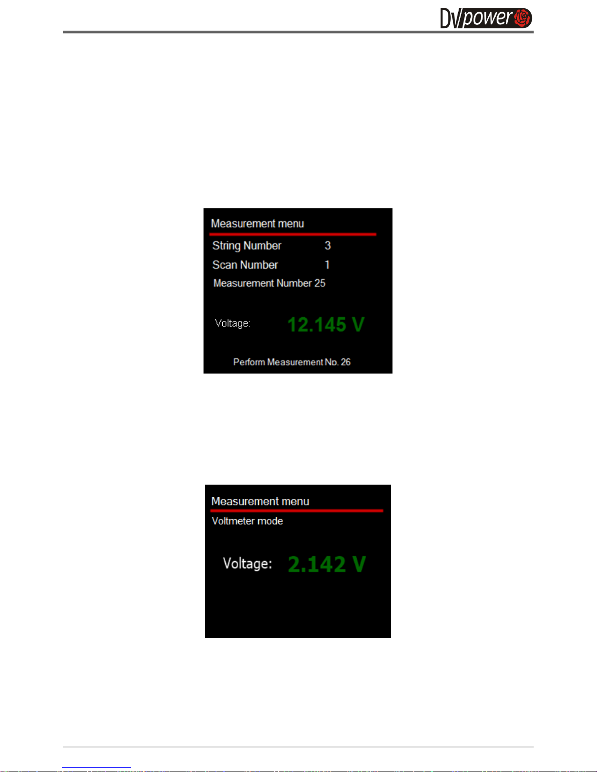
After configuring test parameters, the test is started by pressing the START button and the device switches to
the Voltage Recorder Mode. It enables the measured voltage value to be previewed, and stored in the
BVR11 internal memory (Figure 3-5). Data is recorded in the Scan ID device memory location. If already used
Scan ID is selected a message: "Memory location is already used" will be displayed. The user can decide to
keep the same scan ID in which case the previously recorded data will be overwritten.
3.2.2.2. Voltmeter mode
By pressing the ENTER button while in the Main menu, the BVR11 goes into the Voltmeter mode for
continuous measurement of battery voltage. In this mode the voltage values are previewed but not stored in
the device internal memory. The display layout during the Voltmeter mode is shown in the Fig. 3-7.
3.2.2.3. Current probe mode
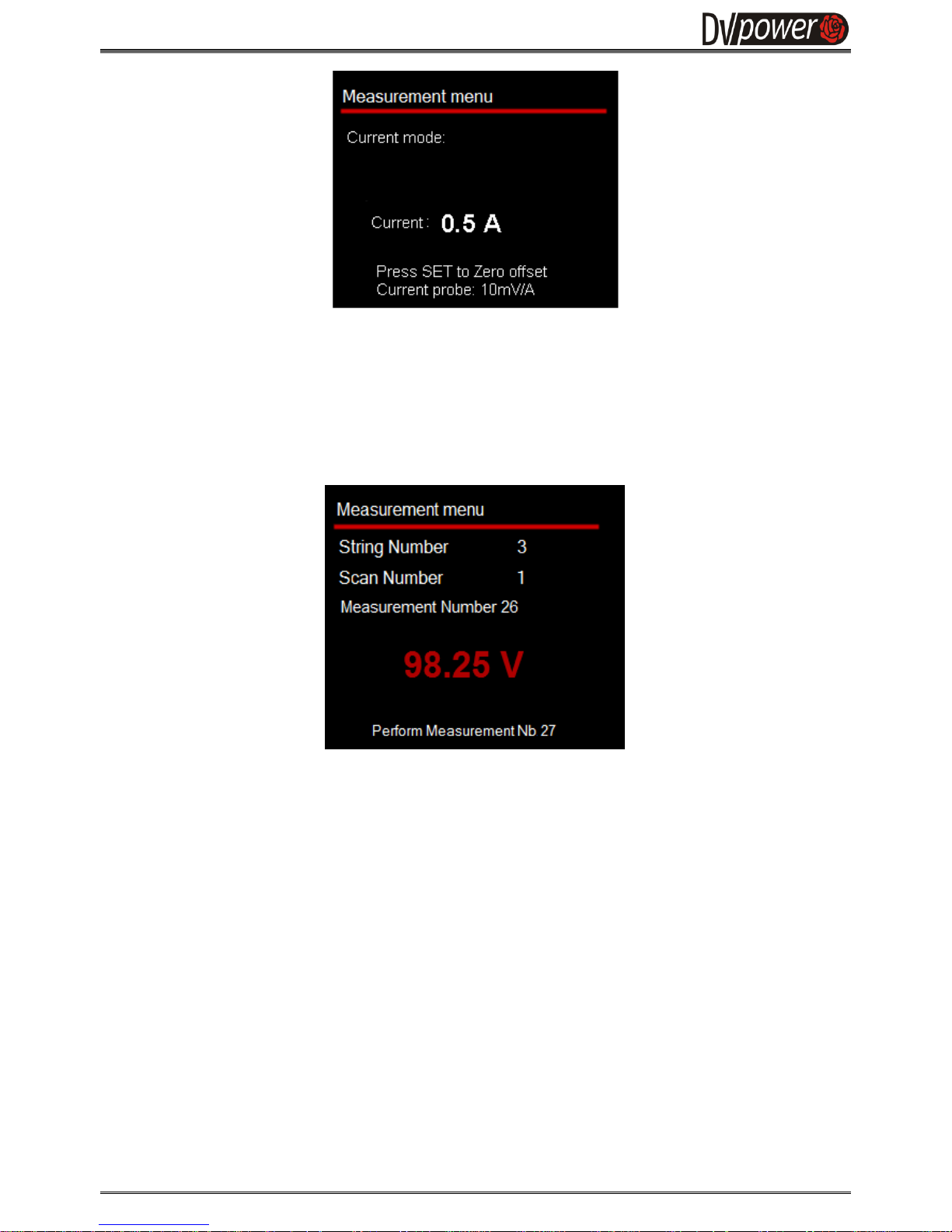
By pressing the ENTER button while in the Voltmeter mode the BVR11 goes into the Current probe mode
for continuous measurement of a float battery current. In this mode current values are previewed and stored
in the devices internal memory. The display layout during the Current probe mode is shown in the Fig. 3-8.
Figure 3-7:
The Measurement
Menu – Voltmeter mode
Figure 3-6:
The Measurement
Menu – Voltage
Recorder mode
Page 10
Battery Voltage Recorder BVR11
M-B011VR-202-EN 10
3.2.2.4. String voltage measurement
When the BVR11 detects voltage values within the range of a user selected string limit values in the
Settings menu (Section 3.2.3), the BVR11 automatically enters in the String measurement mode. In this
mode, the BVR11 stores measurement results in a special memory location assigned to the String
values set of measurements.
The String measurement for the example in the Fig. 3-9 corresponds to the memory location 3.1.0.
Individual cell voltages for the corresponding string are memorized as measurement numbers 3.1.1,
3.1.2, 3.1.3 etc.
In case the user wants to repeat one of previous measurements, the return to the previous measurement
is enabled by pressing the LEFT button on the device.
If any of the test parameters need to be changed, return to the Main Menu screen by pressing STOP.
Note: Test results in the Voltage Recorder mode are automatically saved to the SD Card.
The test results are displayed in different colors based on the value and defined limits:
in green, if the result is within the limits, followed by a beep sound
in blue, if the result is above the upper limit, followed by an extended sound
in red, if the result is below the lower limit, followed by an extended sound
Figure 3-9:
String voltage
measurement – Voltage
recorder mode
Figure 3-8:
The Measurement
Menu – Current probe
mode
Page 11
Battery Voltage Recorder BVR11
M-B011VR-202-EN 11
3.2.2.5. Ambient temperature measurement
The Measurement menu supports the ambient temperature measurement mode, as well. A temperature is
measured automatically with every voltage measurement.
Temperature results will be automatically saved in the Memory Menu under the same ID number as the scan
ID number.
3.2.3. Memory Menu
The MEM button retrieves a preview of the saved battery voltage, string voltage, current and ambient
temperature measurements. After reaching the maximum allowed number of measurements (1,000 scans,
with maximum of 250 measurements per string), the device automatically records the next test data sequence
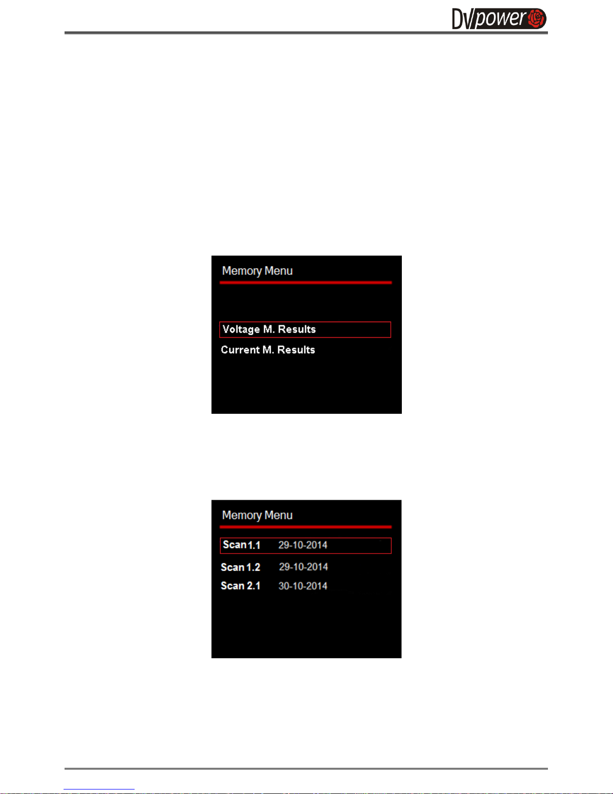
by overwriting memory locations of the previously recorded data set. After pressing the MEM following screen
appears
Choosing one of the above shown options the following screen appears.
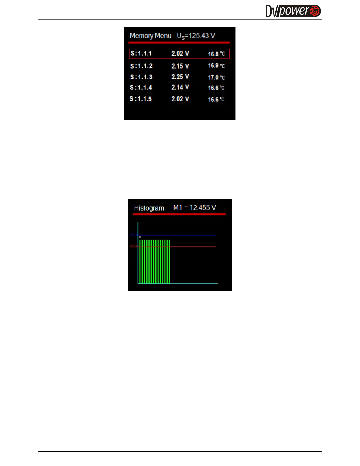
By pressing UP/DOWN buttons a user can navigate through the list of already saved test records. If selecting
the Scan 1.1 by pressing the ENTER button, a new screen will display all measured cell voltages for the
corresponding Scan Number 1, for the String Number 1.
Figure 3-11:
The Memory Menu
Figure 3-10:
The Memory Menu
Page 12
Battery Voltage Recorder BVR11
M-B011VR-202-EN 12
Ambient temperature values are displayed next to each cell voltage measurement, (Fig 3-12).
Pressing the UP/DOWN buttons moves the selection to the next/previous test. Pressing the LEFT/RIGHT
buttons switches to the next/previous five scans at a time.
The BVR11 automatically sorts all measurements by a date. A single scan recorded under the test name
1.2.3. represents the recorded voltage value for the cell Nb. 3 in the String Nb. 1, acquired during the
Scan Nb. 2 of that string.
When a particular test is selected and the ENTER button is pressed, the histogram graph of those
particular test results are displayed (Figure 3-11).
3.2.4. Settings Menu
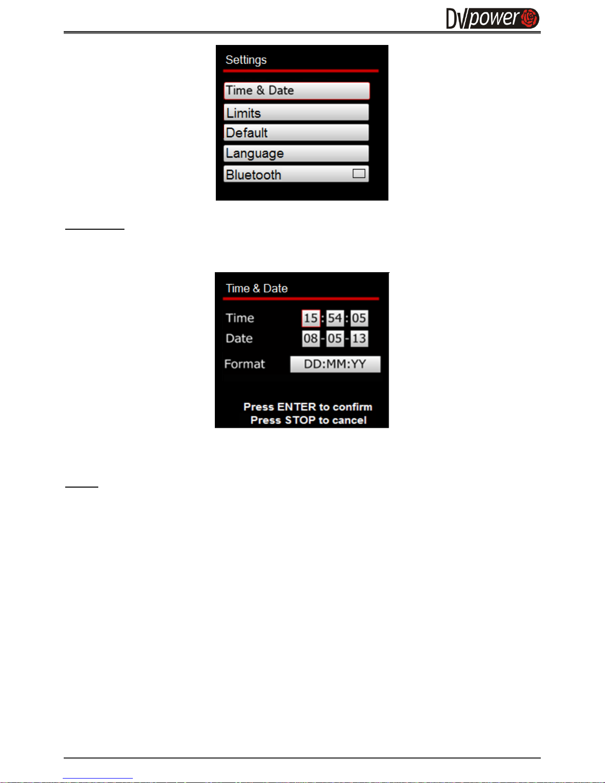
If the device is turned ON for the first time, or some additional system settings are required, pressing the SET
button will display the Settings menu, as illustrated below. In the Settings menu, the Limits, Bluetooth, Time
& Date, and Language parameters can be modified. The UP and DOWN buttons are used for navigation and
the ENTER button for activating the selected submenu.
Figure 3-13:
The Memory Menu –
Battery Voltagehistogram of performed
cell scans
Figure 3-12:
The Memory Menu
Page 13
Battery Voltage Recorder BVR11
M-B011VR-202-EN 13
Time & Date
Time and date information are displayed in the form as presented in the Fig. 3-15.
Date format can be selected in one of the three formats, by pressing the UP button in the Format field.
Limits
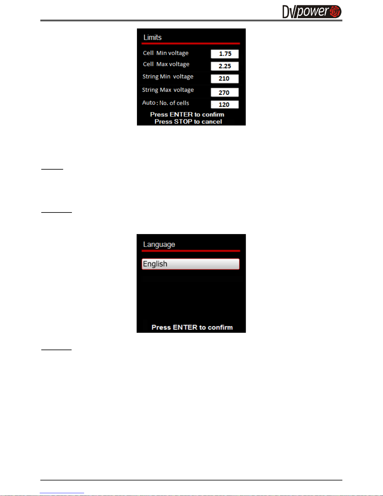
By selecting Limits, the user enters in the Limits screen, as shown in the Fig. 3-16. On this screen the
user can enter Minimum and Maximum voltage limit values for the entire string as well as for individual
cells.
In case the user prefers to use an automatic String limits calculation, based on the entered cell limits and
number of cells in the string, the user should enter a number of cells in the Auto: No. of cells field.
In this way, the BVR11 calculates String limits as:
- String Min voltage: No. Of cells x Cell Min voltage
- String Max voltage: No. Of cells x Cell Max voltage
Figure 3-14:
TheSettings Menu
Figure 3-15:
TheTime & Date
screen
Page 14
Battery Voltage Recorder BVR11
M-B011VR-202-EN 14
In case the value in the field “Auto: No. of cells” is equal to 0, the user should provide the string and cell limit
values by his/her choice.
Default
By selecting the Default option, all limits will be set to predefined values that correspond to the 2V cell type.
The cell voltage limits are set to 1,75 V and 2,35 V, and the string voltage limits are set for a 24 V battery
string to 21.00 V and 28,20 V.
Language
In the Language section, the user may select the displayed language.
Bluetooth
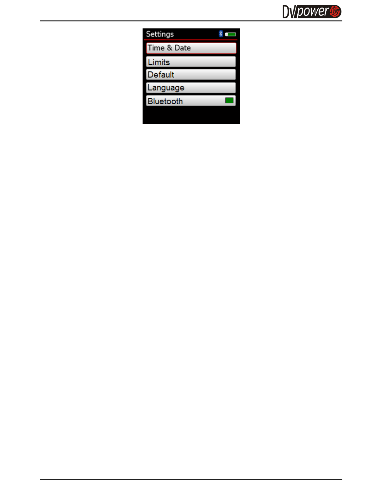
The Bluetooth communication is switched on by pressing ENTER when the Bluetooth entry box is selected.
The Bluetooth communication symbol appears in the upper right corner.
Figure 3-17:
TheLanguage screen
Figure 3-16:
Limits screen – Automatic
calculation of String limits based
on entered number of cells
Page 15
Battery Voltage Recorder BVR11
M-B011VR-202-EN 15
If the user is satisfied with the selected options, all the selections can be confirmed by pressing ENTER.
Figure 3-18:
Bluetooth selection
Page 16
Battery Voltage Recorder BVR11
M-B011VR-202-EN 16
4. SD Card Initialization Error Messages
The BVR11 device has one 2 GB Micro SD card installed. It is used to store internal device information, test
data and it enables data export.
4.1. Initialization failure during startup of the BVR11
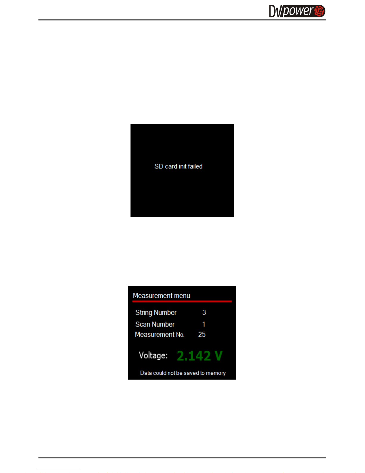
The SD card is initialized during the device startup stage. If there is no SD card in the SD card slot, or if the
initialization is not successful, the following message will be displayed.
4.2. Initialization failure in Measurement menu
In case the BVR11 fails to memorize measured voltage values in the Measurement menu, the device will
display the error message for three seconds and return to the Main Menu. The status message will be
displayed in the Measurement Menu as presented in the Figure 4-2.
.
Figure 4-1:
Error message
"SD Card init failed"
Figure 4-2:
Error message
"Data could not be
saved to memory"
Page 17
Battery Voltage Recorder BVR11
M-B011VR-202-EN 17
5. Troubleshooting
Measurement Parameters
The highest resolution of device readings is always displayed in the Measurement and Memory menus.
Full scale
Resolution
Voltage
range
30 V
10 mV
500 V
100 mV
Table 5.1: Resolution and full scale for each measurement range
Typical accuracy of BVR11 is ± (0,1% rdg + 0,1% F.S) for voltage, with the full scale values shown in the
Table 5.1.
If suspected the device is presenting inaccurate results, the following tests should be performed:
5.1. Checking voltage measurement accuracy
To check the voltage measurements in both ranges, an appropriate test should be performed.
In order to perform a test at ± 30 V range, please take the following steps:
1. Take a 6 V stable voltage source (6 V battery)
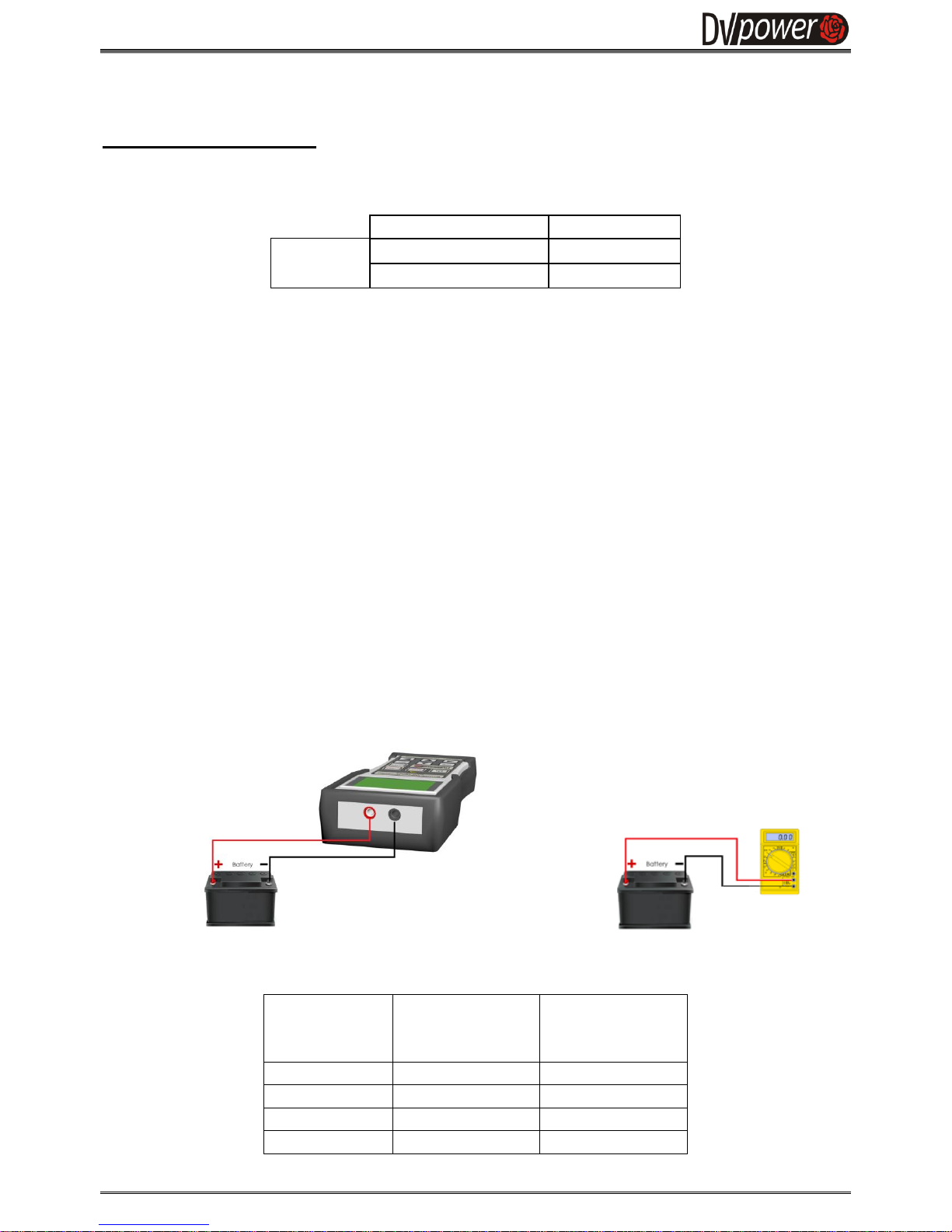
2. Connect the BVR11 device and a test battery as shown in the Figure 5.1.
3. Set the test on the BVR11 device as described in the Section 3.2.1: go to the Main menu, select the
first test voltage from the Table 5.1 and start the test. Read the voltage value.
4. Connect the digital voltmeter and the 6 V test battery as shown in the Figure 5.2.
5. Read the voltage value measured by the voltmeter. Compare the voltage values measured by the
voltmeter to the BVR11 measured values.
6. If voltage values do not differ from the BVR11's specified measurement accuracy, the device is
measuring correctly.
Figure 5-1. Voltage measurement check Figure 5-2. Voltage measurement check
Perform the same test procedure with the values indicated in the Table 5.2.
Set voltage
U [V]
Measured voltage
by BVR11
U [V]
Measured voltage
by voltmeter
U [V]
6
24
60
375
Table 5.2 - Voltage measurement accuracy check
Page 18

Battery Voltage Recorder BVR11
M-B011VR-202-EN 18
6. Customer Service
Before calling or sending an e-mail to Customer Service for assistance, please perform the following steps:
1. Check all cable connections.
2. Try the test on another instrument, if available.
3. Perform the troubleshoot procedure
4. Have the following information available:
• Instrument serial numbers, hardware configuration, and software revision
• Exact description of the problem, including the test object information, error messages and the
sequence of events before it appeared
• List of solutions that have been tried
The Customer Support Department can be reached at:
Local support (Sweden): +46 8 731 78 24
International support: +46 70 0925 000
E-mail: [email protected]
Note: Email communication is preferred for support issues, since the case is then documented and traceable.
Also, the time zone problems and issues with occupied telephones do not occur.
Page 19

Battery Voltage Recorder BVR11
M-B011VR-202-EN 19
7. Packing the Instrument for Shipment
If you need to send the instrument to DV Power for servicing, please contact the DV Power Customer
Service for return instructions at:
Local support (Sweden): +46 8 731 78 24
International support: +46 70 0925 000
E-mail: [email protected]
Note: DV Power is not responsible for shipping damage. Please protect each instrument from shipping
and handling hazards carefully. Please ensure protective covers are securely in place. Instruments
should be sent to DV Power freight pre-paid, unless other arrangements have been authorized in
advance by DV Power Customer Service.
To prepare an instrument for shipment, please follow these instructions:
1. Disconnect and remove all external cables. Do not include manuals, cables, and transducer
connecting rods unless recommended by DV Power Customer Service.
2. Reuse the original packing material if it is available. If it is not, pack the instrument for shipment
according to the instructions for fragile electronic equipment. It is recommended use two-wall
minimum corrugated cardboard box with a minimum 5 cm (2 inch) thick poly foam padding, or a
wooden crate with minimum of 5 cm (2 inch) thick poly foam padding all around.
Page 20

Battery Voltage Recorder BVR11
M-B011VR-202-EN 20
8. Technical Data
Mains Power Supply
Battery
Type 1 Cell – 2 600 mAh Li-Ion
Voltage 3,7 V
Charge time 6 hours
AC Adapter
Input voltage 90 – 264 V AC, 50/60 Hz
127- 370 V DC
Output voltage 12 V DC
Output current 0,5 A
Measurement
Cell voltage measuring range: 0 – 30 V DC
Measuring
range
Typical accuracy
± 30 V DC
± (0,1% rdg + 0,1% FS)
10 mV
± 500 V DC
± (0,1% rdg + 0,1% FS)
100 mV
Temperature:
-50 °C - +260 °C /-58 °F - +500 °F
Display
Type: TFT LCD 3.1 in
Viewing Area:
43,2 mm x 57,6 mm / 1.8 in x 2.3 in
Resolution: 320 x 240 pixels
Communication with PC
USB
Bluetooth
Memory
Internal: 2 GB SD Card
Real time clock
Precision: ±5 seconds per month
Calendar: 100 year with leap year detection
Time retention: 10+ years (battery removed)
Page 21

Battery Voltage Recorder BVR11
M-B011VR-202-EN 21
Environmental conditions
Temperature:
-10 °C - +45 °C / 14 °F - +113 °F
Maximum relative humidity 95 % for
temperatures up to 31 °C/88
o
F, decreasing
linearly to 40 % relative humidity at 55 °C/ 131
o
F
Dimensions and Weight
Dimensions (L x W x D):
223 mm x 98 mm x 46 mm
8.77 in x 3.85 in x 1.81 in
Weight: 0,5 kg / 1.1 lbs,
Warranty
Three years
Low Voltage Directive:
Directive 2014/35/EU (CE conform).
Applicable standards, for a class I instrument, pollution degree 2,
Installation category II: IEC EN 61010-1
Electromagnetic Compatibility:
Directive 2014/30/EU (CE conform).
Applicable standard: EN 61326-1
All specifications herein are valid at ambient temperature of + 25 °C and recommended accessories.
Specifications are subject to change without notice.
Page 22
Battery Voltage Recorder BVR11
M-B011VR-202-EN 22
9. Accessories
Instrument with included accessories
Article No
Battery Voltage Recorder BVR11
BVR11X-NN-00
DV-B-Win software including mini USB cable
Transport bag and carrying belts
Mains power adapter
Recommended
Article No
Sense cables
S2-0122-BPBP
Current clamp 30/300 A with internal battery supply and extension 5
m
CACL-0300-08
Page 23

Battery Voltage Recorder BVR11
M-B011VR-201-EN 23
IBEKO Power AB 2016
This Manual is a publication of IBEKO Power AB, 181 50 Lidingö, Sweden.These documents are
protected by Swedish Copyright law and international contracts as intellectual property of the IBEKO
Power AB. The documents contain confidential information of IBEKO Power AB which is protected by
patent, copyright, trademarks or otherwise as inventions, trademarks or creations of IBEKO Power
AB. The reproduction, duplication, transmission or use of these documents or its contents is not
permitted without express prior written consent of the IBEKO Power AB.
IBEKO Power AB shall not be liable for any incidental or consequential damages resulting from the
performance or use of this document or its product. This document has undergone extensive
technical approval before being released. IBEKO Power AB reviews this document at regular
intervals, and includes appropriate amendments in subsequent issues. While every effort has been
made to keep the information herein as accurate and up to date as possible, IBEKO Power AB
assumes no responsibility for errors or omissions or for damages resulting from the use of the
information contained herein. IBEKO Power AB cannot take over liability resulting in any way from the
use of this document or parts thereof.The product information, pictures, drawings and all technical
data contained within this manual are not contractually binding and IBEKO POWER AB reserves the
right to make modifications at any time to the technology and/or configuration without prior notice.
Insofar as any information, software or documentation is made available, any liability for defects as to
quality or title of the information, software and documentation especially in relation to the correctness
or absence of defects or the absence of claims or third party rights or in relation to completeness
and/or fitness for purpose are excluded except for cases involving willful misconduct or fraud.
In case of a disagreement between the translation and the original English version of this Manual, the
original English version will prevail.
Manufacturer Contact Information
IBEKOPOWERAB
Box 1346, 181 25 Lidingö, Sweden
Fax: + 46 8 731 77 99
E-Mail: [email protected]
Website: http://www.dv-power.com
 Loading...