

DVIGear HyperLight DVI-2300-AOC-TX, HyperLight DVI-2300-AOC-RX, HyperLight DVI-2301-AOC-TX, HyperLight DVI-2301-AOC-RX Quick Start Manual
Page 1
DVI-23xxx-AOC
DVI Active Optical Cables
Quick Start Guide
Introduction
DVIGear’s HyperLight® Series is a new generation of advanced Active Optical Cables (AOC) that employs
cutting edge technology to deliver unprecedented resolution, performance and value. HyperLight DVI
cables provide robust features in a rugged yet compact and lightweight form factor. They are fully
HDCP 1.4 compliant and support signals with data rates up to 4.95 Gbps. These features enable
HyperLight cables to support any Single-Link DVI resolution with cable lengths up to 100 meters.
These cables are plenum-rated (UL CMP-OF), compact, lightweight and highly exible. Constructed
using a hybrid design of 4x POF (Polyuorinated Optical Fiber) and 6x copper wires, they are rugged,
yet exible, with a minimum bend radius of just two millimeters. To minimize cable diameter, two
removable DVI docking connectors may be detached, revealing a connector cross section that
measures just 13.9 x 14.2 millimeters. The docking connectors include xation screws for added
security, as do the removable cable pull covers. These features make the cables easy to install
even in narrow conduits, as well as in plenum spaces.
HyperLight cables are designed for use in mission critical applications where image quality and
dependability are paramount. The video signals are transmitted over four optical bers, which make
them immune to interference from environmental noise. The optical transmission path provides a
very low RFI / EMI prole, which allows the cables to be installed in sensitive applications with strict
security requirements. The cables draw power from the connected DVI source, eliminating the need
for an external power supply. HyperLight AOC cables are ideally suited for applications that require
ultra-high resolution DVI signals to be extended over long cable runs with awless image quality.
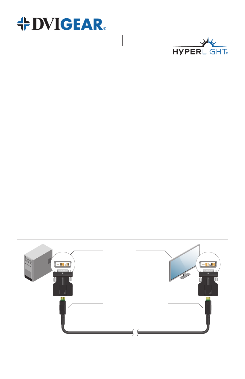
Typical Application
DVI DisplayDVI Source
TRANSMITTER
Note: Always use the supplied DVI docking connector on both ends of this cable.
TX
This cable is powered by the DVI source,
which eliminates the need for an external power supply.
DVI-23xxx-AOC DVI Active Optical Cable
DVIGear, DVIGear & Design, and HyperLight are trademarks of DVIGear, Inc.
and may not be used without the prior written permission of DVIGear, Inc.
RECEIVER
DISPLAY
DISPLAY
ReceiverTransmitter
RX
1
Page 2
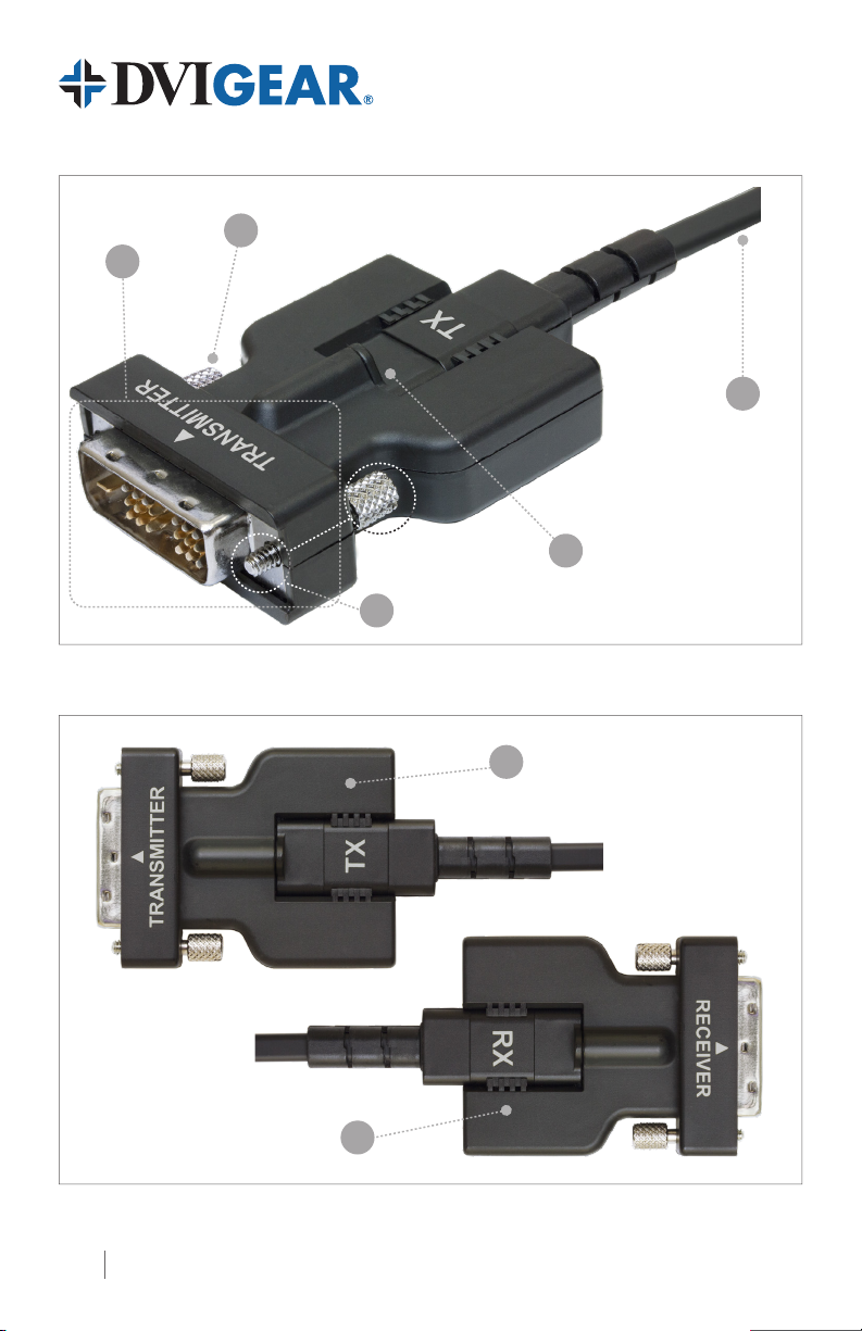
2
1
5
4
2
Cable Mated in DVI Docking Connector
3a
3b
TX / RX Cable Ends Mate with Transmitter / Receiver Docking Connectors Respectively
2
Page 3

DVI Active Optical Cables
Quick Start Guide
DVI-23xxx-AOC
1. DVI Connector
2. DVI Securing Screw
3a. Transmitter Docking Connector
3b. Receiver Docking Connector
Connect the Transmitter (TX) end to the DVI source device.
Connect the Receiver (RX) end to the display device.
Insert and tighten screws on the DVI connectors when mating
with the source and display units.
Insert TX side of cable into the docking connector labeled
Transmitter / Source. Secure with provided screw.
(1)
Insert RX side of cable into the docking connector labeled
Receiver / Display. Secure with provided screw.
(1)
4. Fixation Screw Used to ensure the docking connector is secured to the cable.
The DVI signal is transported from the TX module to the RX
5. Hybrid Optical / Copper Cable
Note 1: WARNING: Take care that the DVI Docking Connectors are used as shown. Mating the TX or RX cable
ends to the wrong docking connector could cause damage to the cable.
Note 2: WARNING: Take care that the cable is not forced to bend beyond its minimum bend radius.
module over a hybrid optical / copper cable. The minimum
bend radius
(2)
for this cable is 2 mm.
Installation Instructions
1. If the cable must be pulled through a conduit or other tight space, please install the
cable pull cover using the two screws provided. After the cable pull has been completed,
remove this cover.
2. This cable includes two DVI docking connectors. One is labeled “Transmitter” on the front
side and “Source” on the back; the other is labeled “Receiver” and “Display.” Connect the
TX end of the cable to the Transmitter docking connector, and the RX end of the cable to
the Receiver docking connector.
3. Connect the Transmitter / Source docking connector to a DVI source device (such as a PC).
4. Connect the Receiver / Display docking connector to a display or projector.
5. First, turn ON the Display and then turn ON any signal distribution equipment (if used).
Finally, turn ON the source device. Test the system to ensure proper performance.
Info 1: This cable requires very low power, which it draws from the connected DVI source. This eliminates the
need for an external power supply.
Info 2: This cable may be connected to an HDMI source and/or display using a DVI to HDMI Adapter Cable
(Model No. DVI-8511b or DVI-8511c).
Note 3: WARNING: This cable is UNIDIRECTIONAL and will not function if it is installed backward.
Always connect the TX end (labeled Transmitter / Source) to the source device and the RX end (labeled
Receiver / Display) to the display.
3
Page 4

Cable Mating Diagram
Detaching and Attaching the DVI Docking Connector and Cable Pull Cover to the Cable End
2
1
4
3
1. Hold the DVI Connector with the docking slot facing upwards.
2. Insert the correct end of the cable into the appropriate DVI docking connector until it
clicks rmly in place. Ensure that the TX cable end is seated in the Transmitter docking
connector. The RX cable end should be seated in the Receiver docking connector.
3. Secure the cable end and the docking connector with the provided xation screw.
4. Two protective cable pull covers (p.n. DVI-2300-AOC-CVR) are included that can be
attached to the cable ends to facilitate ease of installation in narrow conduits as well as
in plenum spaces. Secure each cover with two provided Phillips head screws prior to
running the cable, then remove when nished.
(4)
Note 4: WARNING: The electronics in the DVI Docking Connectors are length-specic. Do not swap docking
connectors from cables of alternate lengths as this could result in degraded performance. Spare docking
connectors can be ordered as follows:
DVIGear
Model No.
DVI-2300-AOC-TX DVI-AOC, Passive Docking Connector, Tx 10 – 30 m
DVI-2300-AOC-RX DVI-AOC, Passive Docking Connector, Rx 10 – 30 m
DVI-2301-AOC-TX DVI-AOC, Active Docking Connector, Tx 40 – 100 m
DVI-2301-AOC-RX DVI-AOC, Active Docking Connector, Rx 40 – 100 m
DVI-23xxx-AOC-QSG-01 / August.2018
4
Product Description
Cable
Lengths
© 2018 DVIGear, Inc.
All Rights Reserved
DVIGear
1059 Triad Court, Suite 8
Marietta, GA 30062 USA
Toll Free: 888.463.9927
Tel: +1.770.421.6699
Fax: +1.770.234.4207
support@dvigear.com
www.dvigear.com
 Loading...