

Page 1
Maximum Cable Lengths
Resolution
Clock Freq. CAT-5e
CAT-5e
DVI-TPS-TX90
DVI-TPS-RX90
MultiPort TPS ExtenderQuick Start Guide
(1)
CAT-6A
(2)
CAT-6A
(1)(2)
1024x768 @60Hz
1280x720p @60Hz
1920x1080i @60Hz
1280x1024 @60Hz
1920x1080p @60Hz
1920x1200 @60Hz
1600x1200 @60Hz
Note 1: With Long Reach rmware installed. This rmware supports pixel clock frequencies up to 148.5 MHz.
Please contact DVIGear technical support or your dealer to change or upgrade device rmware.
Note 2: CAT6A S/FTP (550 MHz) cable must be used to achieve these distances.
65.00 MHz 328.1 ft. (100 m) 524.9 ft. (160 m) 393.7 ft. (120 m) 590.6 ft. (180 m)
73.84 MHz 328.1 ft. (100 m) 524.9 ft. (160 m) 393.7 ft. (120 m) 590.6 ft. (180 m)
74.25 MHz 328.1 ft. (100 m) 524.9 ft. (160 m) 393.7 ft. (120 m) 590.6 ft. (180 m)
108.00 MHz 328.1 ft. (100 m) 524.9 ft. (160 m) 393.7 ft. (120 m) 590.6 ft. (180 m)
148.50 MHz 328.1 ft. (100 m) 492.1 ft. (150 m) 393.7 ft. (120 m) 557.7 ft. (170 m)
152.90 MHz 328.1 ft. (100 m) N/A 393.7 ft. (120 m) N/A
162.00 MHz 328.1 ft. (100 m) N/A 393.7 ft. (120 m) N/A
Installation
WARNING: Ethernet ports are designed to connect to 10/100 Ethernet products. Do not connect
Ethernet appliances to TPS IN or TPS OUT ports as it may result in damage to the equipment.
1. Set the switch on the front panel to the Normal position.
2. Connect a CAT-X twisted pair cable to the TPS OUT on the transmitter unit.
3. Connect the other end of the CAT-X twisted pair cable to the TPS IN on the receiver unit.
4. Connect an HDMI signal source to the HDMI IN port on the transmitter unit.
5. Connect an HDMI display device (e.g. projector) to the HDMI OUT on the receiver unit.
6. To use the bi-directional pass-through data lines, connect desired devices to the transmitter
and receiver units. See examples in table
7. Connect the supplied External AC Power Adapter to either unit. The other unit will
automatically receive power over the twisted pair cable connected between the TPS ports.
Ethernet
RS-232
Infra-Red
Note 3: Examples of optional devices that are supported over the MultiPort TPS twisted pair link.
Use LAN cables to connect an Ethernet device (e.g. switch) to the Ethernet port on the Transmitter unit
and a network device (e.g. projector) to the Ethernet port on the Receiver unit.
Use serial cables to connect a controller unit (e.g. touch panel) to the RS-232 port on the Transmitter unit,
and serial controlled device (e.g. projector) to the RS-232 port on the Receiver unit.
Connect the supplied IR Transmitter to the IR OUT port of the transmitter unit.
Connect the supplied IR Receiver to the IR IN port on the Receiver unit.
(3)
below.
Introduction
DVIGear’s MultiPort TPS Extender supports long-range extension of HDMI (v1.4) signals over a single CAT-X
twisted pair (TP) cable at distances of up to 180 meters (590 ft.). These units also support bi-directional
RS-232, Infra-Red, 10/100 BaseT Ethernet, and PoE over the same twisted pair link.
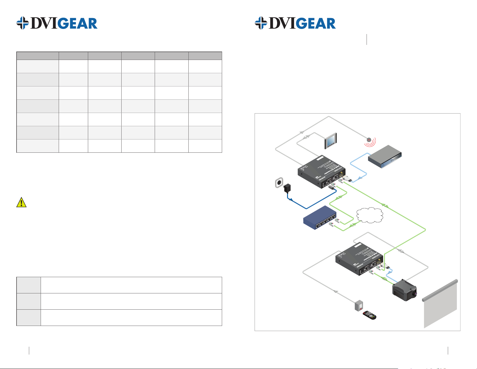
Typical Application
IR cable
IR Transmitter
Serial
cable
Touch panel
Blu-Ray or DVD Player
HDMI cable
12V DC
Power Adaptor
DVI-TPS-TX90
TPS connection
LAN
CAT-X up to 180m
Internet
Ethernet switch
LAN
Serial cable
HDMI
cable
DVI-TPS-RX90
Remote powered
LAN
IR cable
IR Receiver
HD Projector
Projection screen
MultiPort TPS Extender: DVI-TPS-TX90 and DVI-TPS-RX90
DVI-TPS-TX90_RX90-QSG-01 / August.20124 1
Page 2

DVI-TPS-TX90
DVI-TPS-RX90
MultiPort TPS ExtenderQuick Start Guide
8
7
DVI-TPS-TX90 Front View
6
DVI-TPS-TX90 Rear View
5 4
8
1
2
3
1
1. Status Indicator LEDs:
HDCP HDCP encrypted video
VIDEO Video signal
LINK TPS connection
LIVE
2. IR IN/OUT Connect IR Transmitter to IR OUT. Connect IR Receiver to IR IN.
3. HDMI IN/OUT Connect source device to HDMI IN. Connect display to HDMI OUT.
4. TPS IN/OUT
5. Ethernet IN/OUT
6. DC IN Connect AC Power Adapter to either unit, other is powered by TP link.
7. RS-232 IN/OUT Connect to Ethernet switch and/or devices - see Installation.
8. NORMAL / PROG Set to NORMAL position. PROG is only for qualied technical personnel.
Lit Continuously Blinking Off
signal transmission
transmission
TPS connection
detected and Normal
operation
—
Use a high quality TP cable to connect TPS OUT to TPS IN.
Connect to Ethernet switch and/or devices - see Installation.
detected and Power
save mode
Device powered and
ready to use
—
—
(1)
No HDCP encryption
No video signal
transmission
TPS connection failed
between TX and RX
No power supply
or out of order
(2)
(2)
7
2
DVI-TPS-RX90 Front View
Note 1: These units enter Power Save mode when no signal is detected on the input. Normal operation is
restored when a signal appears on the input. Power Save mode is not supported with Long Reach rmware.
Note 2: Ethernet ports are designed to connect to 10/100 Ethernet products. Do not connect Ethernet devices to
TPS Input or Output as it may result in damage to the equipment.
Infra-Red Accessories Locking DC Plug
6
DVI-TPS-RX90 Rear View
3
IR Units
IR Transmitter
IR Receiver
5 4
DVIGear • 1059 Triad Court, Suite 8, Marietta, GA 30062 • Tel: 770.421.6699 • Toll Free: 888.463.9927 • Fax: 770.234.4207 • sales@dvigear.com • www.dvigear.com2 3
Connector Connect to
IR OUT
IR IN
Twist 90° clockwise to lock
 Loading...