

Page 1
DVI-TPS-TX95-HDMI
DVI-TPS-RX95-HDMI
Quick Start Guide
Introduction
DVIGear’s DVI-TPS-TX95-HDMI and DVI-TPS-RX95-HDMI comprise a high performance HDBaseT™
twisted pair extension system designed for a wide range of professional HDMI signal distribution
applications. They support both HDMI and DVI signal formats with or without HDCP encryption and can
reliably transmit signals over a single CAT-X cable with lengths up to 600 ft. (~180 meters). In addition
to HDMI and DVI signals, these products also support bidirectional RS-232 and IR, as well as Ethernet
pass-through over the same CAT-X cable.
These extenders can stand alone or serve as end points for DVIGear’s MXP Series Digital Matrix
Routing Switchers to form a fully-integrated AV system. The MXP Series offers an unprecedented
range of cross-platform routing capabilities, enabling I/O congurations from 9x9 up to 80x80. System
designers can choose from a wide range of sixty (60) types of I/O cards. DVIGear’s family of TPS I/O
cards are fully compatible with the TPS 95 Series Extenders. These extenders can be powered locally,
remotely point-to-point, or remotely through the switcher. When remote powering is disabled, all the
DVIGear TPS devices are HDBaseT compliant and can be used with third-party products.
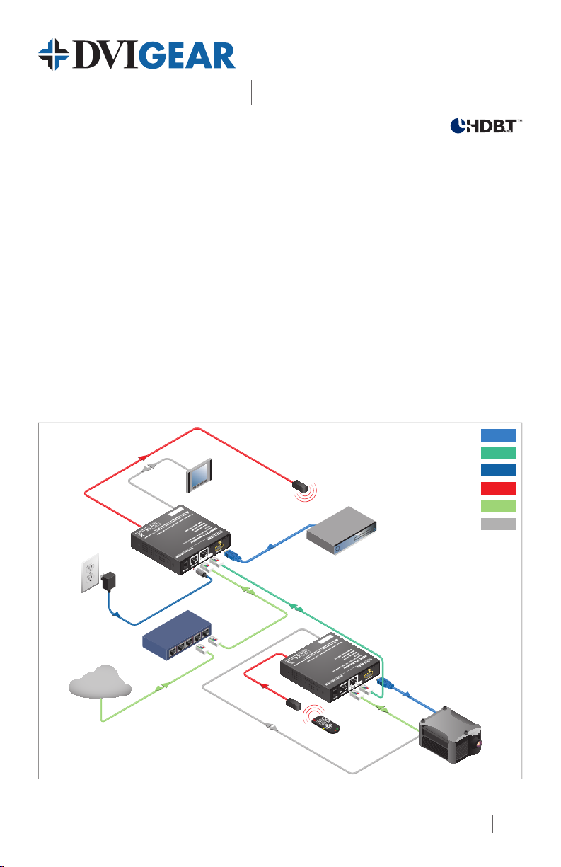
Typical Application
IR Transmitter
Touch panel
12V DC
Power Adapter
HDMI cable
HDMI TPS Extender
DVIGear SHR™ Cable
TPS CAT-X
Power Cable
Blu-Ray or DVD Player
IR Connection
Ethernet
RS-232
DVI-TPS-TX95-HDMI
Ethernet switch
Internet
IR Receiver
TPS CAT-X connection
up to 600 ft. (~180m)
DVI-TPS-RX95-HDMI
(remote powered)
DVI-TPS-TX95-HDMI and DVI-TPS-RX95-HDMI HDMI TPS Extenders
HDMI cable
HD Projector
1
Page 2
1
2
3
4
10
9
4
10
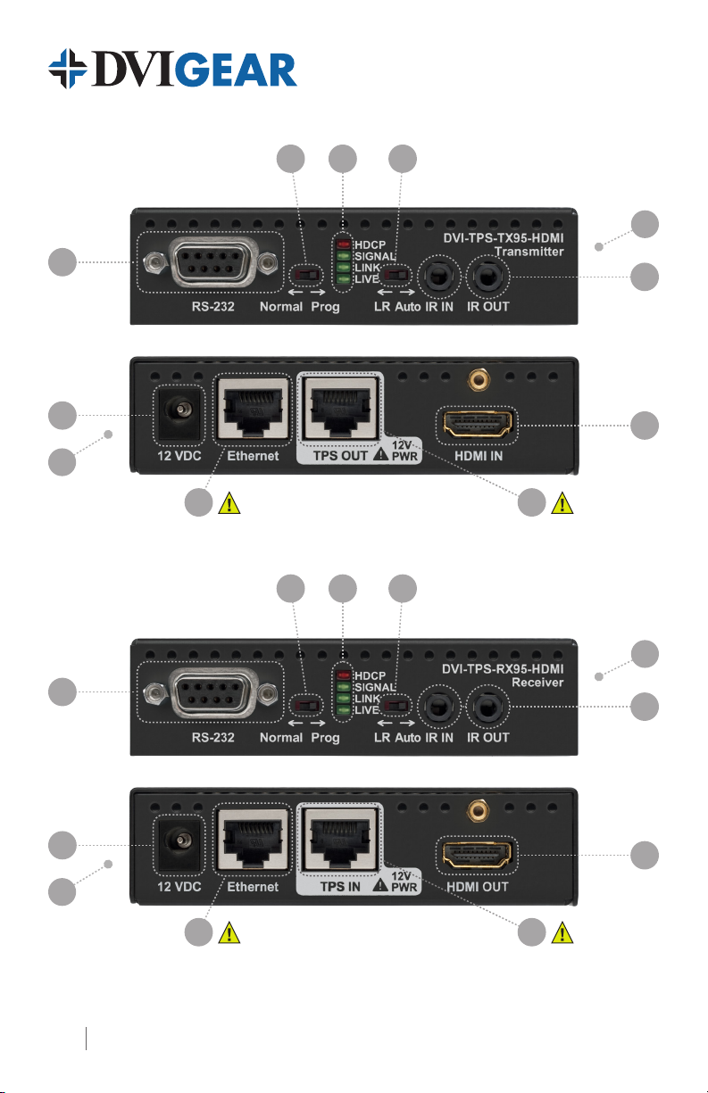
DVI-TPS-TX95-HDMI Front View
DVI-TPS-TX95-HDMI Rear View
8 7
1
2
DVI-TPS-RX95-HDMI Front View
3
5
6
4
5
9
4
DVI-TPS-RX95-HDMI Rear View
6
8 7
2
Page 3
HDMI TPS Extender
Quick Start Guide
DVI-TPS-TX95-HDMI
DVI-TPS-RX95-HDMI
1. Status Indicator LEDs Lit Continuously Blinking Off
HDCP HDCP-encrypted video
signal transmission
VIDEO SIGNAL Video signal transmission
LINK TPS connection detected and
HDBaseT or LR Link Mode
LIVE
2. NORMAL / PROG
Set the RS-232 switch to NORMAL position. PROG is for service by
qualied technical personnel.
—
—
—
TPS connection detected
and LPPF Link Mode
Device powered and
ready to use
No HDCP encryption
No video signal
transmission
TPS connection failed
(1)
between TX and RX
No power supply
present or malfunction
3. LR / AUTO Use these switches to toggle between TPS link modes - see page 5.
4. Remote PWR Jumper A remote power settings jumper is located on the side of the unit - see page 4.
5. IR IN/OUT Connect the IR Transmitter to IR OUT. Connect the IR Receiver to IR IN.
6. HDMI IN/OUT Connect source device to HDMI IN. Connect display to HDMI OUT.
7. TPS IN/OUT Use a high quality TP cable to connect TPS OUT to TPS IN - see warning below.
8. Ethernet IN/OUT Connect to Ethernet switch and/or devices - see warning below.
9. 12 VDC IN Connect AC Power Adapter to TX and/or RX. Settings vary - see page 4.
10. RS-232 IN/OUT Connect to Ethernet switch and/or devices - see Installation.
Note 1: These units enter Low Power Partial Functionality (LPPF) Mode when no signal is detected on the input.
Normal operation is restored when a signal appears on the input. LPPF is not supported with Long Reach Mode.
WARNING: Ethernet ports are designed to connect to 10/100 BaseT Ethernet products only.
Do not connect any device to the TPS connector unless you are sure they are compatible.
Connecting incompatible devices with similar connectors may cause harm to the devices.
Installation: Stand-Alone Operation
1. Remove power from all devices (installing devices while powered may cause damage).
2. Set the RS-232 switches on the front panels of the TX and RX to the Normal position.
3. Set the TPS link mode with the LR / AUTO switch on the front of the units (see page 5).
4. Set the TX remote power mode
5. Connect a CAT-X twisted pair cable to the TPS OUT on the transmitter unit.
6. Set the RX remote power mode
7. Connect the other end of the CAT-X twisted pair cable to the TPS IN on the receiver unit.
8. Connect an HDMI signal source to the HDMI IN port on the transmitter unit.
9. Connect an HDMI display device (e.g. projector) to the HDMI OUT on the receiver unit.
(2)
with the jumper on the side of the TX (see page 4).
(2)
with the jumper on the side of the RX (see page 4).
3
Page 4

10. To use the bidirectional pass-through data lines such as those mentioned in the table below,
connect desired devices to the transmitter and receiver units.
11. Supply the extenders with 12 VDC power. If remote power is enabled on both sides (see
section on remote power below), the power adapter can be placed at either end. The other
unit will automatically receive power over the twisted pair cable connected between the
TPS ports. If remote power is disabled on either or both units, then both TX and RX must be
powered separately.
Ethernet
RS-232
Infra-Red
Note 2: Never connect any third-party device to DVIGear devices while TPS remote power is enabled. The TPS
remote powering must only be used with TPS 95 Series extenders and MXP Series TPS I/O boards. Using it with other
devices may cause devices to be damaged.
Note 3: Table above contains examples of optional devices that are supported over the TPS twisted pair link. Note
that IR cannot be routed through the MXP Series Digital Matrix Routing Switchers.
Use LAN cables to connect an Ethernet device (e.g. switch) to the Ethernet port on the Transmitter unit
and a network device (e.g. projector) to the Ethernet port on the Receiver unit - see warning on page 3.
Use serial cables to connect a controller unit (e.g. touch panel) to the RS-232 port on the Transmitter unit,
and serial controlled device (e.g. projector) to the RS-232 port on the Receiver unit.
Connect the supplied IR Transmitter to the IR OUT port of the transmitter unit.
Connect the supplied IR Receiver to the IR IN port on the Receiver unit.
Remote Power Options
The TPS 95 Series TX and RX may either be powered separately
by power adapters or one device (TX or RX) may be used to power
the other remotely over the TPS link. Additionally, the units may
also be remotely powered by the MXP Series TPS I/O boards.
Remote powering can be enabled or disabled on the extenders by
conguring jumpers located on the sides of the units.
1. First, remove power from the TX and RX.
2. Next, remove the small access panel (shown removed below) on the sides of the units to reveal
the pins and jumper block.
3. To enable the remote power function, place the jumper block onto all the pins. The remote
powering feature must be congured on both TX and RX in order for this feature to be enabled.
4. To disable remote power, place the jumper block onto the upper line of pins only.
When remote powering is enabled on both TX and RX, the power adapter can be placed at either end.
State
Enabled
Disabled
(Default)
TX RX
Note 4: AWG 26 cables are not recommended with remote powering as they reduce maximum cable distances.
4
Page 5

HDMI TPS Extender
Quick Start Guide
DVI-TPS-TX95-HDMI
DVI-TPS-RX95-HDMI
TPS Link Modes
The TPS 95 Series extenders provide user selection of three different modes for the TPS connection.
HDBaseT
Long Reach (LR)
Low Power Partial
Functionality (LPPF)
Note 5: For available resolutions and extension distances, see Maximum Cable Lengths table below.
Supports higher data rates, but limits maximum extension distances. In this mode, if there
is no active video, the units will automatically switch to Low Power (LPPF) TPS link Mode.
Supports greater extension distances, but does not support HDMI signals with a pixel clock
rate greater than 148.5 MHz. The Low Power (LPPF) mode is not available while in this mode.
While in HDBaseT Mode, if there is no active video signal, the units will automatically switch
to Low Power (LPPF) mode. This mode only supports Ethernet, RS-232 and IR signals.
Toggling Between TPS Link Modes
Both TX and RX have a TPS Link Mode toggle switch with two settings: Auto and LR. If either unit is
set to LR, both of them switch into LR mode. If both units are set to Auto and there is a valid video
signal on the transmitter, the TPS Link Mode will be HDBaseT. If the video signal is not active, the
devices go into Low Power (LPPF) mode. LPPF mode is not available while using LR mode.
Mode
LR
LR
HDBaseT / LPPF
Transmitter Receiver
LR
Does not matter
Auto Auto
Does not matter
LR
If a TPS 95 Series extender and an MXP Series TPS I/O board are paired, the board will force the extender
to use the settings of the matrix. In this case, the extender’s TPS Link Mode switch has no effect.
Note 6: Always use Auto Mode and disable remote power operation when paired with third-party devices.
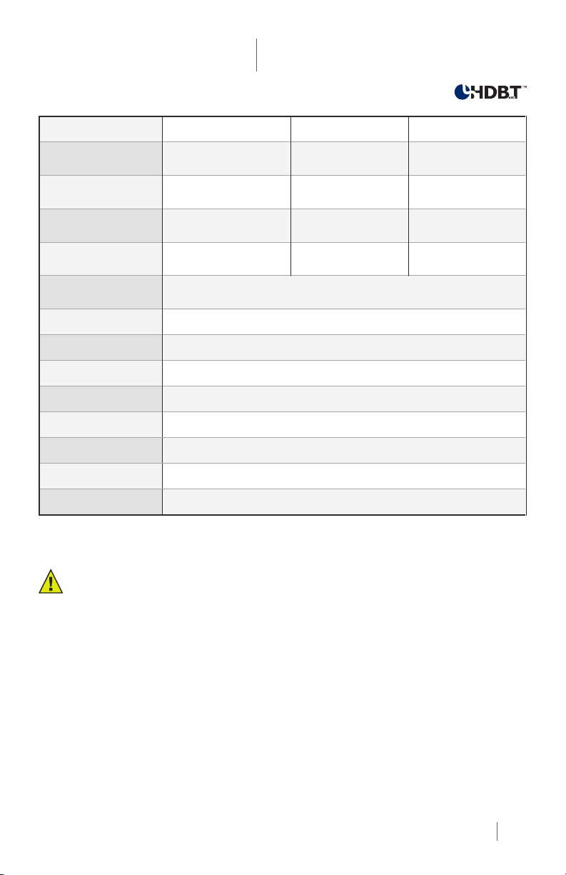
Maximum Cable Lengths
Resolution
1920x1080p
@60Hz / 24bpp
Clock
Freq.
148.5 MHz 330 ft. (~100 m) 425 ft. (~130 m) 400 ft. (~120 m) 600.0 ft. (~180 m)
CAT-5e (AWG 24) CAT-6A (AWG 23)
HDBaseT Long Reach
(7)
HDBaseT Long Reach
(8)
(7)
1920x1200
@60Hz
1600x1200
@60Hz
4096x2160
@30Hz
Note 7: Long Reach Mode supports HDMI signals with pixel clock rates up to 148.5 MHz.
Note 8: CAT6A S/FTP (550 MHz) 23AWG twisted pair cable must be used to achieve these distances.
152.9 MHz 330 ft. (~100 m) N/A 400 ft. (~120 m) N/A
162.0 MHz 330 ft. (~100 m) N/A 400 ft. (~120 m) N/A
297.0 MHz 230 ft. (~70 m) N/A 330 ft. (~100 m) N/A
5
Page 6

Bidirectional Pass-through Signals
In these extenders, the video signal travels in one direction only, from the TX to the RX. However, the
RS-232, IR, and Ethernet pass-through signals are bidirectional. If used, they require connections on
both sides of the extension system.
Ethernet
WARNING: Ethernet ports are designed to connect to 10/100 BaseT Ethernet products only.
Do not connect any device to the TPS connector unless you are sure they are compatible.
Connecting incompatible devices with similar connectors may cause harm to the devices.
The Ethernet port on the RX or on the TX can be connected to a LAN hub, switch or router with a
LAN cable (see warning above). The Ethernet connection on the other extender unit then operates
as an Ethernet uplink port. The extenders support 10/100 Mbps. data transfer rate, as well as direct
access using a crossover cable. The Ethernet port has a built-in Auto Crossover feature, allowing it to
recognize and support both patch cables and crossover cables.
RS-232
The serial port pass-through connection supports any standard RS-232 device. Devices can be
connected to the extender using the 9-pin D-sub female connector on both TX and RX. Use a straightthrough serial cable to connect a DTE controlling device to an extender, and use a cross serial cable when
pairing the extender with a DCE device being controlled. The extenders support all standard baud rates,
parity bits, and serial settings. These settings can be congured using the third-party RS-232 devices.
Note 9: Please consult the user manuals for the third-party RS-232 devices to determine whether they are DTE or
DCE devices. The TPS 95 Series extenders operate as DCE devices.
Infra-Red (IR)
The extenders support bidirectional IR transmission when
operating point to point. One IR transmitter/receiver set is
included with each extender pair.
(10)
Both IR-TX and IR-RX
use standard 3.5 mm mini-jack connectors. The IR-TX uses
a mono connector, and the IR-RX uses a stereo connector.
To extend the IR signal over the TPS link, connect the IR-RX to the IR IN connector on the front panel of
one of the units, then connect the IR-TX to the IR OUT connector on the other unit. To use bidirectional IR
communication, an additional IR TX/RX pair is necessary, which can be ordered from DVIGear.
Note 10: IR extension is only available when using a point-to-point conguration. Only 1x each of the IR-TX and
IR-RX are supplied with each extender pair. Please contact DVIGear to order additional pairs if necessary.
Units
IR Tx
IR Rx
Connector Connect to
IR OUT
IR IN
Installation: Integrated with MXP Series Matrix Switchers
1. Remove power from all devices (installing devices while powered may cause damage).
2. Set the RS-232 switches on the front panels of the TPS extenders to the Normal position.
3. In this case, the TPS Link Mode switch on the extenders has no effect because the connected
I/O board forces the extender to use the settings of the matrix.
4. Set the remote power modes
separately - see page 7. For more detailed information, please see the MXP Series User Manual.
6
(11)
of the TPS I/O boards. Each port can be set for remote powering
Page 7

HDMI TPS Extender
Quick Start Guide
DVI-TPS-TX95-HDMI
DVI-TPS-RX95-HDMI
5. Set the remote power
(11)
modes on the extender units with the same method as is mentioned in the
stand-alone case - see page 4.
6. The TPS 95 Series extenders can be remotely powered
(11)
using the MXP Series TPS I/O boards
via the twisted pair cable that links the TPS In/Out ports. To achieve this, an optional external
power supply (p.n. DVI-MXP-PSU12V) must be connected to the 2-pin phoenix connector on each
TPS I/O board - see information below. If the remote power feature is disabled on the connected
TPS I/O board, then a local power adapter must be used to power the TPS extender unit.
7. Connect the extender(s) and the matrix board(s) using CAT-X
(11)(12)
cable(s). Connect the
transmitters’ TPS OUT connectors with the input boards’ TPS IN connectors and the receivers’
TPS IN connectors with the output boards’ TPS OUT connectors.
8. Connect the video source(s), sink(s) and the desired accessory device(s) to the MXP Series
matrix switcher. MXP Series TPS I/O boards do not support IR pass-through.
9. Next connect the video source(s), sink(s) and the desired accessory device(s) to the extenders.
10. Connect the power cord of the MXP Series switcher into an AC outlet and power ON the unit.
11. Supply power to the other connected units (sources, displays, etc.).
Note 11: Never connect any third-party device to DVIGear devices while TPS remote power is enabled. The TPS
remote powering must only be used with TPS 95 Series extenders and MXP Series TPS I/O boards. Using it with other
devices may cause devices to be damaged.
Note 12: For best results, CAT6A S/FTP (550 MHz) 23AWG twisted pair cable is highly recommended.
Remote Power Options with MXP Series Matrix Switchers
The TPS extenders can be powered remotely by the connected TPS I/O board. The remote powering
feature can be enabled or disabled separately on each I/O port of the matrix board using jumper settings.
1. To congure the remote power settings, power OFF the matrix switcher, then remove the
desired boards from the MXP Series frame.
2. The remote power pins are located directly behind each TPS port. To enable remote powering
on a port, place the jumper block onto the set of pins behind that port. To disable remote
powering on a port, remove the jumper block from the set of pins behind that port.
3. Connect the optional external power adapter (p.n. DVI-MXP-PSU12V) to the 2-pin phoenix
connector on the board.
4. Finally, set the required power mode for the extenders - see page 4.
Please see the remote power diagram on page 8 for more details.
State
Enabled
Boards Extenders
12VDC / 6.67A external
power adapter - ordered
separately.
Disabled
(Default)
Note 13: For detailed information, please see the MXP Series TPS I/O cards User Manual.
Note 14: AWG 26 CAT-X cables are not recommended with remote powering as they reduce cable distances.
7
Page 8

Integrated Remote Powering Options Diagram
Please see the remote power sections on pages 4 and 7 for instructions on conguring remote power.
TPS CAT-X
Power Cable
Power Send
Power Adapter
Remote Power
Enabled
12V DC
Disabled
(local)
Enabled
DVI-TPS-RX95-HD
No Power
Send
DVI-TPS-RX95-HD
Power Send
Remote Power
Disabled
12V power on TPS connector. Only use with compatible devices!
12V power on TPS connector. Only use with compatible devices!
S/PDIF I/O 1 S/PDIF I/O 2 S/PDIF I/O 3 S/PDIF I/O 4 S/PDIF I/O 5 S/PDIF I/O 6 S/PDIF I/O 7 S/PDIF I/O 8
TPS OUT 1 TPS OUT 2 TPS OUT 3 TPS OUT 4 TPS OUT 5 TPS OUT 6 TPS OUT 7 TPS OUT 8
12V 4A
MX-TPS-OB-S
DC IN
12V power on TPS connector. Only use with compatible devices!
S/PDIF I/O 1 S/PDIF I/O 2 S/PDIF I/O 3 S/PDIF I/O 4 S/PDIF I/O 5 S/PDIF I/O 6 S/PDIF I/O 7 S/PDIF I/O 8
8 CH TPS OUTPUT BOARD WITH DIGITAL AUDIO
TPS OUT 1 TPS OUT 2 TPS OUT 3 TPS OUT 4 TPS OUT 5 TPS OUT 6 TPS OUT 7 TPS OUT 8
12V 4A
MX-TPS-OB-S
DC IN
12V power on TPS connector. Only use with compatible devices!
8 CH TPS OUTPUT BOARD WITH DIGITAL AUDIO
TPS IN 1 TPS IN 2 TPS IN 3 TPS IN 4 TPS IN 5 TPS IN 6 TPS IN 7 TPS IN 8
12V 3A
MX-TPS-IB-S
DC IN
8 CH TPS INPUT BOARD
TPS IN 1 TPS IN 2 TPS IN 3 TPS IN 4 TPS IN 5 TPS IN 6 TPS IN 7 TPS IN 8
12V 3A
MX-TPS-IB-S
DC IN
8 CH TPS INPUT BOARD
Power Adapter
12V DC
Disabled
(local)
No Power
Send
Power Send
Enabled
DVI-TPS-TX95-HDMI
DVI-TPS-TX95-HDMI
Maximum Cable Lengths Between MXP Series TPS Boards and Extenders
The maximum cable extension distances are the same as is mentioned in the table on page 5.
TPS Link Modes
If a TPS 95 Series extender is connected to a TPS I/O board, the matrix board will force the extender
to use the settings of the matrix switcher. In this case, the extender’s TPS mode switch has no effect.
For detailed information see the MXP Series User Manual.
HDBaseT™ and the HDBaseT Alliance logo are trademarks of the HDBaseT Alliance.
8
DVI-TPS-TX95-HDMI_DVI-TPS-RX95-HDMI-QSG-01 / March.2014
DVIGear
1059 Triad Court, Suite 8,
Marietta, GA 30062
Toll Free: 888.463.9927
Tel: 770.421.6699
Fax: 770.234.4207
support@dvigear.com
www.dvigear.com
 Loading...