

Page 1

User Guide
DVI-7520 HDMI HDBaseT Extender Set, 70m
DVI-7525 HDMI HDBaseT Extender Set, 100m
Page 2

TABLE OF CONTENTS
SECTION PAGE
PRODUCT SAFETY ....................................1
PRODUCT LIABILITY ...................................1
1.0 INTRODUCTION ...................................2
2.0 SPECIFICATIONS ................................3-4
3.0 PACKAGE CONTENTS ..............................5
4.0 CONNECTING THE HARDWARE ......................5
5.0 OPERATING THE UNIT .............................10
6.0 TROUBLESHOOTING ..............................10
7.0 LIMITED WARRANTY ..............................11
8.0 REGULATORY COMPLIANCE .......................11
Page 3

WARNING – Product Safety
1. Do not dismantle the product housing or modify the printed circuit board
module as this may result in electrical shock or burn.
2. Do not attempt to service this product yourself as opening or removing the
product housing may expose you to dangerous voltages or other hazards.
Refer all servicing to qualied service personnel.
3. Keep this product away from liquids. Spills into the product housing may
result in re, electrical shock, or equipment damage. If liquid spills into the
housing, unplug the product immediately. Have the product checked by a
qualied service engineer before using it again.
4. Place the product in an even and stable location. If the product falls or is
dropped, it may cause an injury and/or malfunction.
5. Avoid exposing the product to extreme temperatures or to high humidity
levels as this may result in damage to the product.
6. Only use the supplied External AC Power Adapter. The use of other power
adapters may cause this product to fail or may cause a re.
7. Do not twist or exert excessive force on the ends of the connected cables
as this can cause them to malfunction. Take precaution to ensure that all
connected cables are not forced to bend beyond their minimum bend radius.
Product Liability
Every effort has been made to ensure that this product is free of defects.
DVIGear cannot be held liable for the use of this product or for any direct or
indirect consequential damages arising from its use. It is the responsibility of
the users of this product to check that it is suitable for their requirements and
that it is installed correctly.
All rights are reserved. No part of this manual may be reproduced or transmitted
by any form or means, electronic or mechanical, including photocopying,
recording or by any information storage or retrieval system, without the written
consent of DVIGear.
DVIGear reserves the right to revise any of its hardware and software, following its
policy to modify and/or improve its products where necessary or desirable. This
statement does not affect the legal rights of the user in any way. All third-party
trademarks and copyrights are recognized. The DVIGear logo is a registered
trademark of DVIGear, Inc. HDMI™ is a registered trademark of HDMI LLC.
HDBaseT™ and the HDBaseT Alliance logo are trademarks of the HDBaseT
Alliance. All other trademarks are the property of their respective holders.
-1-
Page 4

1.0 INTRODUCTION
DVIGear’s DVI-7520 and DVI-7525 utilize HDBaseT™ technology to provide a
simple and cost-effective solution for extension of uncompressed HDMI or DVI,
embedded audio, bidirectional IR, RS-232 and Ethernet (DVI-7525 only) using a
single twisted pair CAT-X cable.
These extenders support the full range of HDBaseT features, including: 5-play,
support for 4K / 30p (UHD) resolution, bidirectional IR, POH (Power over
HDBaseT) and long-range operation. They support extension of HDMI signals
with 1080p resolution up to 330 ft. (~ 100 meters) and 4K (UHD) resolution up
to 230 ft. (~ 70 meters).
Today there are many HDBaseT products that utilize non-standard
implementations of power over the HDBaseT link. This problem has created
interoperability challenges for system integrators who are faced with HDBaseT
products that do not work with each other or, in some cases, cause equipment
failures. To solve this problem, DVIGear’s DVI-7520 and DVI-7525 include
a fully-compliant implementation of Power over HDBaseT (POH), a key
component of the HDBaseT standard.
Our professional digital distribution products have been serving the industry
for over ten (10) years. DVIGear offers a full line of high-quality Digital Matrix
Routers, Switchers, Splitters, Video Scalers, Up/Down/Cross Converters,
Format Converters, Analog-Digital Converters, as well as a wide range of longreach Digital Cables, Extenders, and Optical Transmission systems.
1.1 Features
The DVI-7520 and DVI-7525 offer several exceptional features:
• Extends HDMI, Ethernet (DVI-7525 only), RS-232, and bidirectional IR
over a single CAT-X cable
• Supports 4K resolutions up to 4096x2160 / 30p
• Supports HDBaseT POH standard with remote power from TX to RX unit
over the CAT-X cable
• Fully HDCP compliant, EDID and CEC transparent
• Extends 1080p HDMI signals up to:
100 meters (DVI-7525) or 70 meters (DVI-7520)
• Extends 4K (UHD) HDMI signals up to:
70 meters (DVI-7525) or 40 meters (DVI-7520)
• Multiple extender pairs can be cascaded for applications that require
extreme distances
• Heavy-duty mounting brackets are included
-2-
Page 5
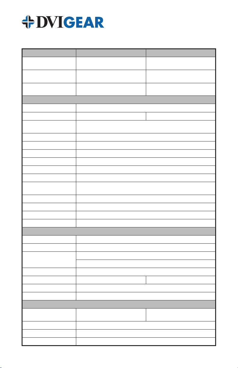
2.0 SPECIFICATIONS
Model
Extender Set
Transmitter
Receiver
DVI-7520:
HDBaseT HDMI Extender Set, 70m
DVI-7520-Tx:
HDBaseT HDMI Transmitter, 70m
DVI-7520-Rx:
HDBaseT HDMI Receiver, 70m
Performance
Video
HDBaseT Class Type
Audio
HDCP
Control
Supports Ethernet (DVI-7525 only), bidirectional IR and RS-232 pass-through
Power
EDID
Cable Equalization
Supported HDTVFormats
Supported PCResolutions
Supports all single-link DVI resolutions up to 1600x1200 and 1920x1200,
Input DDC Signal
Input Video Signal
IR Carrier Freq. Range
RS-232 Baud Rate
Connections / Indicators
HDMI Input / HDMI Output
HDBaseT Interface
IR Remote Control
RS-232
Ethernet Interface
Power
Diagnostic Indicators
Power
Power Consumption
Remote Power
External AC Power Adapter
ESD Protection
DVI-7520 DVI-7525
DVI-7525:
HDBaseT HDMI Extender Set, 100m
DVI-7525-Tx:
HDBaseT HDMI Transmitter, 100m
DVI-7525-Rx:
HDBaseT HDMI Receiver, 100m
Supports HDMI v1.4, HDCP, and CEC
HDBaseT Class B HDBaseT Class A
Supports HDMI embedded audio: up to 7.1 PCM, Dolby Digital TrueHD,
Supports HDMI signals with or without HDCP encryption
Supports local 12VDC power, as well as 48V POH (Tx unit to Rx unit).
Supports HDTV resolutions up to 4096x2160 (4K)
1x Screw-locking 5.5 mm / 2.0 mm female connector
Tx Unit: 10.8 watts (Maximum)
Rx Unit: 10.8 watts (Maximum)
Input: 100-240VAC, 50-60Hz / Output: +12VDC @ 1.5A
and DTS-HD Master Audio
EDID of connected display is transparent
Automatic, adaptive
HDMI resolutions up to 4096x2160 (4K)
5.0 Vpp (TTL)
0.5 to 1.0 Vpp
33-55 kHz @ 5 volts
Up to 115,200 baud
1x 19-pin Female HDMI connector
1x RJ45 with 48V POH
1x IR IN: 3.5mm Stereo Mini-Jack
1x IR OUT: 3.5mm Mini-Jack
1x 3-pin phoenix connector
None 1x RJ45
Power, Status, Link, and HDCP LEDs
Tx Unit: 11.8 watts (Maximum)
Rx Unit: 11.8 watts (Maximum)
48V POH from Tx unit to Rx unit
± 15 kV
-3-
Page 6

2.1 Specications (Continued)
HDBaseT
Category Cable Type
Maximum Extension
Distances
(1)
Maximum Pixel Clock Freq.
Maximum Video Bit Rate
Gain
Resolution Range
Signal to Noise Ratio
Return Loss
Total Harmonic Distortion
Min. / Max. Signal Level
Differential Phase Error
Propagation Delay
Power Over HDBaseT (POH)
4096x2160 / 30p, 1920x1080 / 60p /
> 70 dB @ 100 MHz over 70m cable > 70 dB @ 100 MHz over 100m cable
±10° @ 135 MHz over 70 m cable ±10° @ 135 MHz over 100 m cable
DVI-7520 DVI-7525
Recommended: CAT6A S/FTP (550 MHz) AWG 23
Compliant with TIA/EIA-568B termination standard
up to 230 ft. (70 meters) @
1920x1080 / 60p / 36-bit
up to 130 ft. (40 meters) @
48-bit, and 1920x1080 / 120p
Supports digital signal bit rates up to 3.4 Gbps./color, 10.2 Gbps. total
< 7 µs @ 70 meters < 10 µs @ 100 meters
Fully-compliant implementation of Power over HDBaseT (POH).
Tx unit is a PSE device and Rx unit is a PD device.
Required: CAT5e or better
up to 330 ft. (100 meters) @
1920x1080 / 60p / 36-bit
up to 230 ft. (70 meters) @
4096x2160 / 30p, 1920x1080 / 60p /
48-bit, and 1920x1080 / 120p
Supports pixel clock rates up to 340 MHz
0 - 10 dB @ 100 MHz
800x600 – 1920x1200, 4096x2160 / 30p
< -30 dB @ 5 KHz
< 0.005% @ 1 KHz
< 0.3 Vpp / 1.45 Vpp
Mechanical
Construction
Dimensions (W x D x H)
Weight
Each Unit: 6.8" x 3.9" x 1.0" (173.1 mm x 100.1 mm x 25.6 mm)
Tx Unit: 14.5 oz. (411 grams)
Rx Unit: 15.1 oz.(428 grams)
Heavy-duty steel enclosure with jet black nish
Tx Unit: 14.7 oz.(418 grams)
Rx Unit 15.2 oz.(432 grams)
Environmental
Operating Temp.
Typical Case Temp.
Storage Temp.
Opr. / Strg. Humidity
Environment: +32° to +95° F (0° to +35° C)
Tx Unit: 98.6° F (37° C); Rx Unit: 105.8° F (41° C);
(Ambient Environment 30°C, 10 Hours)
Environment: -4° to +158° F (-20° to +70° C)
10% to 90% (non-condensing)
Regulatory Approvals
TX / RX Units
External AC Power Adapter
FCC, CE, UL, C-UL, CEC, GS, PSE, RoHS
FCC, CE, RoHS
Warranty
Limited Warranty
3 Years Parts and Labor
Accessories
1x User Guide, 1x External AC Power Adapter, 1x IR Transmitter,
Included
Additional AC Power Adapter with USA, Euro, UK, or Australia Plugs (DVI-7520-PS),
Optional
Note 1: Maximum cable lengths using recommended CAT6A S/FTP (550 MHz) AWG 23 cable
1x IR Receiver, 2x 3-pin RS-232 Phoenix Connectors,
4x Mounting Brackets with Screws, 2x HDMI Jack Screws
IR Receiver (DVI-7360-IR-RX), IR Transmitter (DVI-7360-IR-TX),
19” Rack Mount Kit (DVI-7520-RMK)
-4-
Page 7

3.0 PACKAGE CONTENTS
1 2 3 4
Before attempting to use this unit, please check the packaging and make certain
the following items are contained in the shipping carton:
• 1x DVI-7520-TX or DVI-7525-TX HDMI HDBaseT Transmitter
• 1x DVI-7520-Rx or DVI-7525-RX HDMI HDBaseT Receiver
• 1x User Guide
• 1x External AC Power Adapter (+12 VDC)
• 1x IR Transmitter
• 1x IR Receiver
• 2x 3-pin RS-232 Phoenix Connectors
• 4x Mounting Brackets with Screws
• 2x HDMI Jack Screws
Note: Please retain the original packing material in case you need to return the unit. If you
nd any items are missing, contact your reseller or DVIGear immediately. Please have the
Model Number, Serial Number, and Invoice Number available for reference when you call.
4.0 CONNECTING THE HARDWARE
Please study the images below and become familiar with the signal inputs,
outputs, and the location of the power connector.
1 HDCP LED: ON indicates HDCP encrypted signal is present, blinking
indicates non-encrypted signal, OFF indicates no signal.
2 Link LED: monitors the link status between the HDBaseT transmitter and
receiver. When a proper connection is established, the LEDs on both Tx
and Rx are ON, otherwise both LEDs are OFF.
3 Status LED: monitors internal HDBaseT activity, blinking when normal.
4 Power LED: ON when an active power source is applied.
Note: The conguration of the front panel LEDs on the DVI-7520 and DVI-7525 are identical.
-5-
Page 8

Transmitter Unit Rear View
1 2 3 4 5 6 7 8
1 2 3 4 5 6 7 8
1 12 VDC Power Input: screw locking female connector for AC Power Adapter.
2 HDBaseT Output: RJ-45 female connector. See warning below.
3 IR IN: connect IR receiver to send IR signal over CAT-X cable to Rx Unit.
4 IR OUT: connect IR transmitter to accept IR signal from Rx Unit and
output to a source device.
5 RS-232: 3-pin female phoenix connector for serial data pass-through.
6 HDMI Input: female connector; connect to an HDMI or DVI source.
7 Ethernet: RJ-45 female connector (only on DVI-7525).
8 Service Switch: reserved for qualied technical personnel.
Receiver Unit Rear View
1 12 VDC Power Input: screw locking female connector for AC Power Adapter.
2 HDBaseT Input: RJ-45 female connector. See warning below.
3 IR IN: connect IR receiver to send IR signal over CAT-X cable to Tx Unit.
4 IR OUT: connect IR transmitter to accept IR signal from Tx Unit and
output to display device.
5 RS-232: 3-pin female phoenix connector for serial data pass-through.
6 HDMI Output: female connector; connect to an HDMI or DVI display.
7 Ethernet: RJ-45 female connector (only on DVI-7525).
8 Service Switch: reserved for qualied technical personnel.
WARNING: The HDBaseT ports are designed to connect to compatible DVIGear products
only. Do not connect any device to the HDBaseT connector unless you are sure it is compatible.
Connecting incompatible devices with similar connectors may cause harm to the devices.
It is typical for HDBaseT receiver units to operate at higher temperatures than transmitter
units. In order to ensure proper operation and long term reliability, care must be taken to
ensure airow is not restricted in any way.
-6-
Page 9

12 VDC Power
Adapter
DVI-7525-TX
IR Tx
HDBaseT CAT-X
connection
LAN
(DVI-7525 only)
Control Laptop
LAN
(DVI-7525 only)
4K Upscaling
Blu-Ray Player
POH Remote Power
4K Projector
DVI-7525-RX
(remotely powered by transmitter)
IR Rx
This HDBaseT extension system consists of a Transmitter unit (DVI-7520-TX or
DVI-7525-TX) and a Receiver unit (DVI-7520-RX or DVI-7525-RX). To connect
this system, rst remove power from all devices (installing devices while powered
may cause damage). Connect a CAT-X twisted pair cable to the HDBT OUT on
the transmitter unit. Connect the other end of the CAT-X twisted pair cable to
the HDBT IN on the receiver unit. Connect an HDMI or DVI signal source to the
HDMI IN port on the transmitter unit. Connect an HDMI or DVI display device
(e.g. projector) to the HDMI OUT on the receiver unit.
Note: Proper operation of this product depends on the use of the high quality cables. CAT6A
S/FTP (550 MHz) 23AWG twisted pair cable is recommended to maximize extension distances.
4.1 Bidirectional Signals: RS-232, IR, and Ethernet
In these extenders, the video, embedded audio and power travel in one direction,
from the transmitter to the receiver unit. However, the RS-232, IR, and Ethernet
(DVI-7525 only) pass-through signals are bidirectional. If used, they require
connections on both sides of the extension system. To use these bidirectional passthrough data lines, connect desired devices to the transmitter and receiver units.
-7-
Page 10

For RS-232, use serial cables and the supplied
Tx Rx
3-pin phoenix connectors to connect a controller
unit (e.g. touch panel) and serial controlled device
(e.g. projector) to the RS-232 ports on the Tx and
Rx. Please see the drawing of the female phoenix
connector on the unit for RS-232 pin denitions.
These extenders support bidirectional IR via two
separate IR signals. An IR signal may be extended
over the CAT-X cable from Tx Unit to the Rx Unit by doing the following. Connect
the supplied IR Receiver to the IR IN port of the Tx Unit. Next, connect the
supplied IR Transmitter to the IR OUT port on the Rx Unit. To send an IR signal in
the opposite direction (i.e. from Rx to Tx), simply connect the IR Receiver to the IR
IN on the Rx Unit and the IR Transmitter to the IR OUT on the Tx Unit.
IR RX IR TX
Transmitter
Receiver
HDBaseT CAT-X
connection
IR TXIR RX
The DVI-7525 extender pair supports extension of 100BaseT Ethernet over the
CAT-X cable. Take care to only connect compatible devices to the ports marked
“Ethernet” on the rear of the DVI-7525 extender pair. Connecting Ethernet devices
to the HDBaseT ports or connecting HDBaseT devices to the Ethernet ports may
result in damage. Please see the warning at the bottom of page 6.
4.2 Power Connections and POH Remote Power
The DVI-7520 and DVI-7525 are fully compliant with the Power over HDBaseT
(POH) component of the HDBaseT standard. During POH operation, the
transmitter unit functions as a PSE (Power Sourcing Equipment) device that
sends 48 VDC power over the CAT-X cable to the receiver unit, which acts as
a PD (Powered Device). This feature eliminates the need for an external power
supply at the receiver. To maintain compatibility and interoperability with other
POH system components, these products use a sophisticated handshake
feature that prevents power exchange with non-standard (incompatible) devices.
-8-
Page 11

For POH operation, connect the supplied AC Power Adapter to the 12 VDC
Power Input on the transmitter unit and then to a working AC power source.
Once the transmitter unit detects the POH compatible receiver unit, it will provide
power over the CAT-X cable. If non-POH operation is desired, simply connect the
optional AC Power Adapter to the 12 VDC Power Input on the receiver unit. In
this case, the transmitter unit no longer supplies power to the receiver unit.
Note: This product utilizes a locking DC power connector to prevent the power cable from
disengaging. Insert the DC plug into the power input jack on the rear panel, then gently rotate
the locking collar in the clockwise direction until it is secure. To remove the power connection,
simply unscrew the locking collar counter-clockwise and then extract the power cable.
4.3 Mounting Hardware
Above Mount
Below Mount
Each transmitter and receiver unit comes with a pair of mounting brackets to
facilitate installation on furniture or other surfaces. These mounting brackets are
reversible, so the unit may be installed above or below the mounting surface.
To afx each bracket to an extender unit, place the side of the bracket with the
large rectangular ventilation opening against the side of the unit. Next, use the
supplied screws to secure the bracket to the two mounting holes located on the
each side of the extender units. These mounting brackets may also be used to
attach the extender units to the optional 19” Rack Mount Kit (see page 4).
-9-
Page 12

5.0 OPERATING THE UNIT
Once all connections have been made and power has been applied to all
components, this extension system should function immediately. This product
has no adjustments and does not require conguration.
6.0 TROUBLESHOOTING
WARNING: The HDBaseT ports are designed to connect to compatible DVIGear products
only. Do not connect any device to the HDBaseT port of this product unless you are sure it
is compatible. Connecting incompatible devices may cause harm to the devices.
It is typical for HDBaseT receiver units to operate at higher temperatures than transmitter
units. In order to ensure proper operation and long term reliability, care must be taken to
ensure airow is not restricted in any way.
If this unit does not appear to be functioning, make certain the 12 VDC power
adapter is connected securely to a functioning AC power outlet and to the Tx
unit. Check that the Power LEDs on both Tx and Rx units are ON continuously.
If the system fails to display a signal, power OFF all devices and check that the
following connections are properly installed: the Tx unit must be connected to
the source using the shortest, high quality cable possible. The Rx unit must be
connected to the display using the shortest, high quality cable possible. Check
to ensure the CAT-X cable between the Tx and Rx is of the high quality and within
the allowable length as noted on page 4. Verify that none of the cables used show
signs of damage and are not forced to bend beyond their minimum bend radius.
If the IR connection is not functioning, verify that the IR Transmitter and IR
Receiver are connected in the correction conguration according to section 4.1
and that all connectors are securely seated.
Once all connections have been veried, power ON the display device rst
and then the signal source. If the system still fails to display an image, check
to ensure that the HDMI or DVI signal source is compatible with the display
by making a direct connection between the two so as to bypass the HDBaseT
extender pair. If there is still no image then there is a compatibility issue
between the source and the display that must be resolved.
If the problem persists after trying the above suggestions, please contact your
dealer for additional assistance. If the dealer’s technical personnel are unable
to assist you, please contact DVIGear via telephone at 1.888.463.9927 (toll-free
for United States and Canada) or 1.770.421.6699. You may contact DVIGear by
e-mail at support@dvigear.com.
-10-
Page 13

7.0 LIMITED WARRANTY
LIMITED WARRANTY – Subject to the limitations stated below, DVIGear warrants
that this product will be free from defects in materials and workmanship for a
period of three (3) years from the date of purchase.
Should the product, in DVIGear’s opinion, prove defective within the warranty
period stated above, DVIGear, at its option, will repair or replace this product
without charge. Any defective parts replaced become the property of DVIGear.
This warranty does not apply to products that have been damaged due to
accident, unauthorized alterations, improper repair, modications, inadequate
maintenance and care, or use in any manner for which the product was not
intended.
If repairs are necessary under this warranty policy, the original purchaser must
obtain a Return Authorization Number from DVIGear and return the product freight
prepaid to a location designated by DVIGear. After repairs are complete, the
product will be returned, freight prepaid.
The foregoing warranty is the sole and exclusive warranty given by DVIGear,
express or implied, and DVIGear disclaims all implied warranties, including but not
limited to implied warranties of merchantability or tness for a particular use.
LIMITATIONS – The liability of DVIGear with respect to any defective products
will be limited to the repair or replacement of such products. In no event shall
DVIGear be responsible or liable for any damage arising from the use of such
defective products, including but not limited to loss of use, revenue or prot,
whether such damages are direct, indirect, consequential or otherwise and
whether such damages are incurred by the reseller, end-user, or any third-party.
8.0 REGULATORY COMPLIANCE
This product is compliant with appropriate FCC, CE and RoHS rules and
regulations. The supplied AC Power Adapter is compliant with FCC, CE, UL,
C-UL, CEC, GS, PSE and RoHS rules and regulations.
-11-
Page 14

Your Digital Connectivity Experts
Toll Free 888.463.9927
Phone 770.421.6699
Fax 770.234.4207
www.dvigear.com
DVI-7520_DVI-7525-UG-01 / August.2014
DVIGear, Inc.
1059 Triad Court, Suite 8
Marietta, Georgia 30062-2258
 Loading...