

Page 1
DVI-7435
EDID Manager /
Quick Start Guide
Introduction
The DVI-7435 is a high-performance 1x2 DVI splitter with built-in EDID Management. The unit
supports DVI and HDMI 1.3a signals with or without HDCP encryption. It automatically compensates
for DVI copper cables with lengths up to 60 meters (~200 ft.) without the need for user adjustment.
The output signal is stabilized using Pixel Accurate Re-clocking technology, which removes jitter
caused by long cables or poor quality signal sources.
Using Advanced EDID Management, the DVI-7435 can emulate any DVI / HDMI display for continuous
video output, even if the attached display is disconnected or powered off. 100 EDID memories are
provided. EDID memories from 01 to 50 are factory preset and memories from 51 to 98 are user
programmable. Memory 00 is transparent for Output 1 and Memory 99 is transparent for Output
2, which means that the attached display device’s EDID (monitor or projector) will be reported to
the source. Using DVIGear’s Easy EDID Creator (PC) software, users can create their own EDID by
completing four simple steps. More experienced users can use DVIGear’s Advanced EDID Editor
software to manage all settings within the EDID structure and then upload to the DVI-7435 via the
unit’s USB interface.
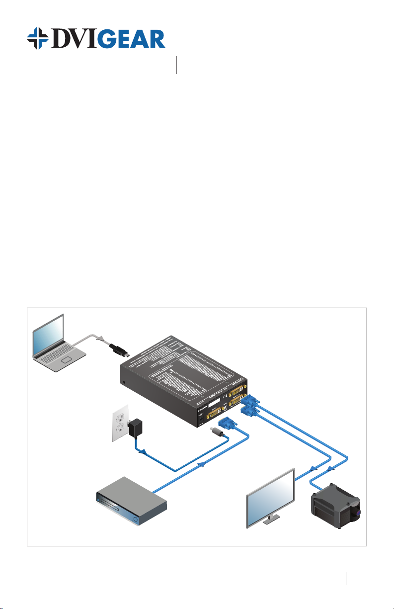
Typical Application
DVI + HDCP 1x2 Splitter
Control Laptop
USB cable
+5 VDC
Power Adapter
DVIGear SHR™
DVI cable up to 60 m.
DVI-7435 EDID Manager / DVI + HDCP 1x2 Splitter
DVI-7435
DVIGear SHR™ DVI cables
MonitorBlu-ray or DVD Player
HD Projector
1
Page 2
1g
1b 1c 1e1d
DVI-7435 Front View
21f1a
34
5
7
DVI-7435 Rear View
6
2
5
Page 3

EDID Manager / DVI + HDCP 1x2 Splitter
DVI-7435
Quick Start Guide
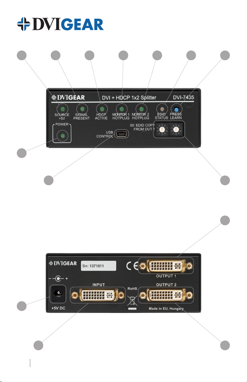
1. Status Indicator LEDs: Function When Blinking
a. Source +5V Source connected —
b. Signal Present DVI signal present on input HDMI signal on input
c. HDCP Active Active HDCP encryption HDCP disabled
d. Monitor 1 Hotplug Hot Plug detect: OUTPUT 1 is connected —
e. Monitor 2 Hotplug Hot Plug detect: OUTPUT 2 is connected —
f. EDID Status EDID validity, rmware version
g. Power Power On —
2. LEARN EDID Press to learn the EDID of the connected display – see page 4.
3. EDID ADDRESS Select the desired EDID using the two rotary switches – see page 4.
4. USB Control Use a USB cable to connect a PC to the unit.
5. OUTPUTS 1 and 2 Connect DVI / HDMI displays to DVI OUTPUT connectors.
6. INPUT Connect DVI / HDMI source device to DVI INPUT connector.
7. 5 VDC
The supplied AC Power Adapter includes a locking DC plug for a
secure connection.
(2)
EDID learn process
successful/failed (pg. 4)
(1)
Note 1: Slow blinking appears if HDMI signal is present on input and output port and fast
blinking indicates HDMI to DVI conversion. To turn ON/OFF HDMI to DVI conversion use
DVIGear’s Control software.
Note 2: The unit shows its 3 digit rmware version after powering on with red and green
blinks (FW 1.1.5 is: 1x red, 1x green, 5x green)
Installation Instructions
1.) Connect a DVI or HDMI source to the DVI input connector.
2.) Connect the monitors (or other sink devices) to the DVI output connectors.
3.) Connect the supplied AC power adapter to the +5V input, then connect the adapter to the AC source.
4.) The unit is ready to be used.
HDCP Enable / Disable Function
The HDCP Active LED indicates the source signal’s HDCP encryption. A blinking green LED indicates
the HDCP OFF function. To enable/disable HDCP operation, turn the rotary switches to memory
address #01 and press the LEARN button for approximately 3 seconds. Alternatively, DVIGear’s control
software may be used to enable/disable HDCP operation.
3
Page 4

EDID Management
To ensure compatibility with all the end-points in an AV system, xing the EDID seen by the source
device is recommended. The DVI-7435 unit has an internal memory that can store up to 100 EDID
values, which can be recalled by using two rotary address switches. Factory preset EDID values are
listed on the top of the unit and are stored in addresses (#01 – #49). EDID addresses (#51 – #98) are
user-programmable. Addresses (#30 – #45) and the Universal EDID address (#49) contain EDID values
that support various HDMI embedded audio formats. Addresses (#00) and (#99) contain the EDIDs
from the current or most recently connected display on OUTPUTS 1 and 2, respectively. Address (#50)
is reserved for factory use.
Selecting an EDID
1.) Turn the EDID ADDRESS rotary switches to the desired position. The available factory preset
EDIDs are listed on the top of the device.
2.) The EDID Status LED provides helpful feedback:
Red: An empty memory or invalid EDID was selected.
Green: A valid EDID has been selected.
3.) The selected EDID is reported to the source device connected to the DVI / HDMI INPUT. Note that
it may be necessary to re-boot the source device in order that it recognize the new EDID.
Learning EDID
1.) Turn the EDID ADDRESS rotary switches to the desired memory location where the EDID of the
attached display is to be stored using address settings (#51 – #98).
2.) Connect the desired display device to the DVI OUTPUT 1 connector on the DVI-7435. EDID
Learning is not available on OUTPUT 2.
3.) Press and hold the LEARN EDID button for approximately 3 seconds.
4.) The EDID Status LED will blink to provide feedback:
Red: The learn process failed to acquire an EDID from OUTPUT1.
Green: The learn process successfully acquired an EDID from OUTPUT1.
USB Connection
The acquired EDID can be modied to meet application requirements using DVIGear’s Advanced EDID Editor
software. For further information please contact DVIGear Technical Support at support@dvigear.com.
DVIGear
1059 Triad Court, Suite 8,
Marietta, GA 30062
Toll Free: 888.463.9927
Tel: 770.421.6699
Fax: 770.234.4207
support@dvigear.com
www.dvigear.com4 DVI-7435-QSG-01 / October.2013
 Loading...