

Page 1
DVI-7425
Quick Start Guide
EDID Manager V4
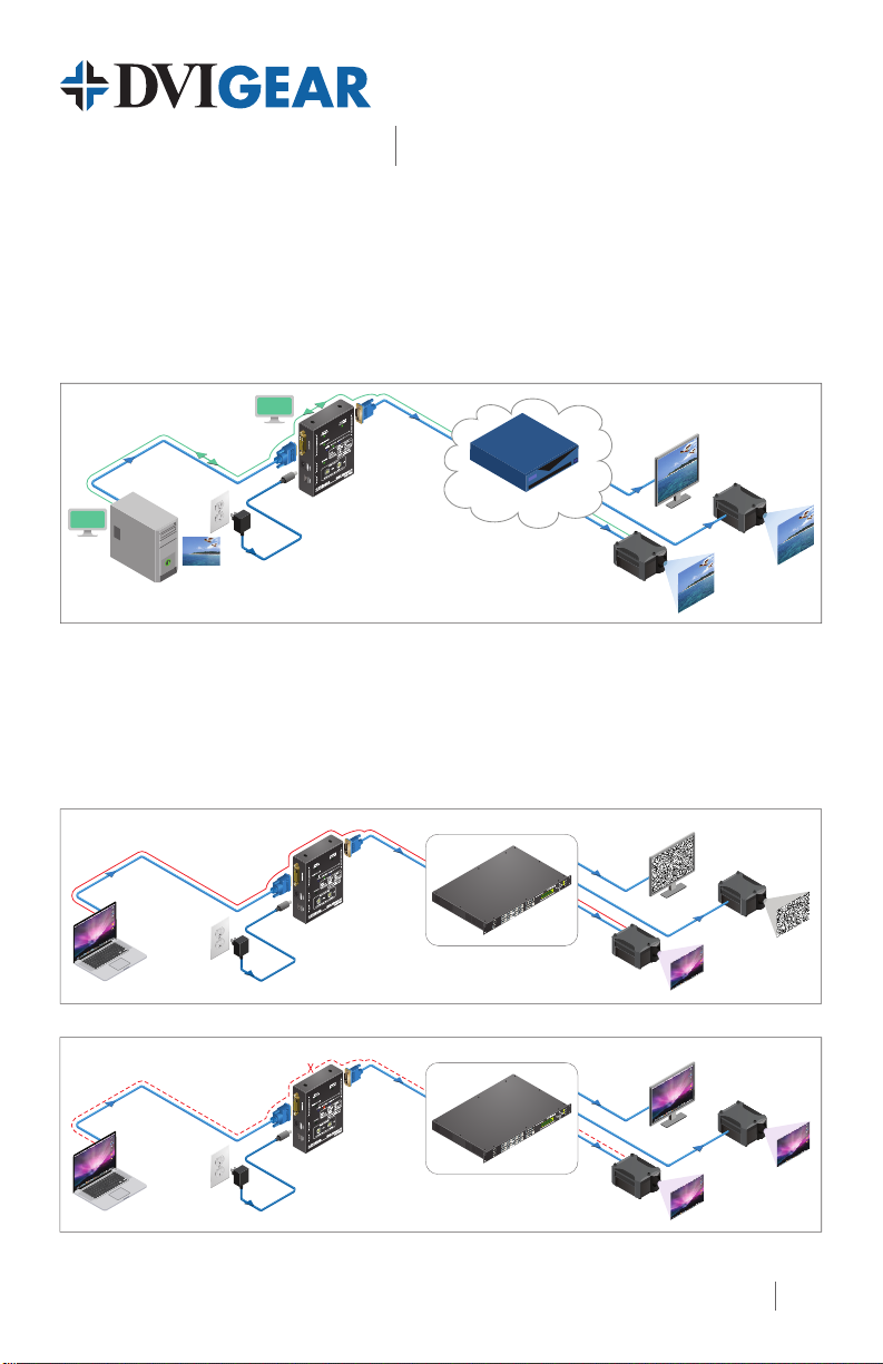
Typical Application
EDID Management
A common EDID can be selected by the EDID Manager v4 in order to provide compatibility with
various end-points (e.g. monitors and projectors) in an A/V system.
EDID is xed
Up to 60m DVIGear
SHR™ cable
EDID
on the input
PC or Mac
HDCP Management
HDCP compatible and non-capable display devices in the same system can lead to setup problems as
some monitors or projectors will not display the signal from the source. In some applications, the EDID
Manager v4 can solve these problems by disabling the unit’s HDCP pass-through function. If the source
content is not HDCP protected, this will force the signal source to output non-HDCP encrypted signal.
EDID
DVI-7425
DVIGear
SHR™ cable
AV System
Monitor
Projector
Projector
Laptop
Laptop
HDCP
encrypted
signal
HDCP
unencrypted
signal
HDCP enabled between source and display
HDCP
encrypted
signal
DVI-7425
HDCP pass-through enabled
HDCP disabled between source and display
HDCP
unencrypted
signal
DVI-7425
HDCP pass-through disabled
HDCP capable AV System
AV System
Non-HDCP
HDCP compatible
Projector
Projector
Monitor
Monitor
Non-HDCP
Projector
Projector
1
Page 2
8
1 7
2 6
3
4
5
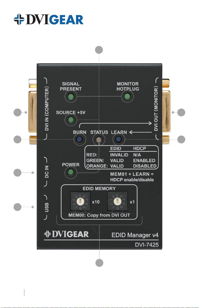
DVI-7425 Top View
2
Page 3

EDID Manager V4
Quick Start Guide
1. DVI INPUT Connect the DVI source device to this connector.
DVI-7425
2. BURN Button
3. 5 VDC INPUT Locking power input connector, +5VDC center pin positive.
4. USB Connector
5. EDID MEMORY
6. LEARN Button
7. DVI OUTPUT Connect the display or other downstream sink to this connector.
8. Status Indicator LEDs:
SIGNAL PRESENT Indicates if a valid DVI clock signal is present on the DVI IN connector.
MONITOR HOT PLUG
SOURCE +5V
POWER Indicates that power is being supplied to the device.
EDID / HDCP STATUS Three-color LED that displays the status of the EDID Manager v4
Red Empty memory or invalid EDID is selected
Reprograms the attached 8x8 DVIGear Matrix switcher’s EDID data this is for legacy support purposes only.
Advanced EDID Management and rmware upgrades are available via
the USB interface.
Select the desired EDID using the two rotary switches – see page 4.
These rotary switches are also used to select HDCP mode – see page 4.
Stores the attached monitor’s EDID data in the selected memory
address between #51 - #79.
Indicates that a powered display device is connected to the DVI OUT
connector and it is sending a valid hot plug signal.
Indicates if +5V power signal is sent to pin 14 of the input DVI
connector by the DVI source device (e.g. PC, Laptop, etc.)
Green Valid EDID data is selected and HDCP pass-through is enabled
Orange Valid EDID data is selected and HDCP pass-through is disabled
Green Flashing Burn / Learn process, or reading connected device’s EDID was successful.
Red Flashing Burn / Learn process, or reading connected device’s EDID failed.
Installation
1.) Connect the DVI source device to the DVI INPUT connector.
2.) Connect the monitor (or sink device) to the DVI OUTPUT connector.
3.) Connect the supplied AC power adapter to the 5 VDC INPUT connector, and then connect the
adapter to a live the AC power outlet.
4.) The unit is now ready for use.
3
Page 4
Select an EDID Setting
1.) Turn the rotary switches to the desired memory address (e.g. 1x10 and 8x1, loads the EDID
info stored in memory number #18).
2.) The status LED will turn Red, Green or Orange:
Red: an empty memory or invalid EDID data was selected
Green: valid EDID data is present at input, HDCP pass-through is enabled
Orange: valid EDID data is present at input, HDCP pass-through is disabled
3.) Now the selected EDID is presented to the source device at the DVI INPUT.
Factory Preset EDID List
The EDID list is on the bottom side of the device. The memory range (#30 - #45) contains HDMI
EDID formats that support various embedded audio formats. Please read the EDID Manager V4
User Manual for further information.
Learning EDID
1.) Turn the rotary switches to the desired memory address where you want to store the
attached display’s EDID (memory addresses #51 - #79).
2.) Connect the display device to the EDID Manager’s DVI OUTPUT connector.
3.) Press and hold the LEARN button for approximately 3 seconds.
4.) The STATUS LED will ash red or green:
Green: the learn process was successful
Red: the learn process failed.
Set HDCP Pass-Through
1.) Turn the rotary switches to memory address #01.
2.) Check the status of the device (STATUS LED):
Green: HDCP pass-through enabled.
Orange: HDCP pass-through disabled.
HDCP
ENABLE
DISABLE
3.) Press and hold the LEARN button for approximately 3 seconds to change HDCP status.
4.) The STATUS LED changes color according to the new HDCP pass-through state.
5.) To select an EDID setting, turn the rotary switches to the desired position.
DVIGear
1059 Triad Court, Suite 8,
Marietta, GA 30062
Toll Free: 888.463.9927
Tel: 770.421.6699
Fax: 770.234.4207
4 DVI-7425-QSG-02 / December.2013
support@dvigear.com
www.dvigear.com
 Loading...