

Page 1
DVI-7317
4K HDMI Fiber Optic
Extender, 1x LCQuick Start Guide
Introduction
Unsurpassed Performance – The DVI-7317 is a high performance 4K Optical Extender that
transmits high resolution HDMI signals over extreme distances using a single ber optic cable.
It supports HDMI v1.4 (HDCP compliant) signals with resolutions up to 3840x2160/30p (4:4:4)
and 3840x2160 /60p (4:2:0) over cable distances of up to 1,000 ft. (~ 300m).
Fiber Optic Extension – The extender set consists of an optical transmitter module that converts the
HDMI signals into light pulses for transmission over a single strand of Multi-Mode or Single-Mode
optical ber cable. An optical receiver module converts the light pulses back to an HDMI signal for
display on a monitor or projector.
Multiple Signals Over One Cable – While the video component of the signal is one-way, the unit
also simultaneously supports extension of bidirectional signals such as EDID and HDCP pass-through.
The data rate from the TX to RX is 10.3Gbps. using the 1310nm wavelength, while the reverse
channel travels from RX to TX over 1550nm at 250 Mbps. The extender uses wavelength-division
multiplexing (WDM) to enable both signals to travel over a single strand of optical ber. This enables
DDC communications without the need for additional cables. These features make the DVI-7317 the
ideal future-proof choice for systems designers and integrators who need to support high resolution
HDMI / DVI signals with or without HDCP over extreme distances.
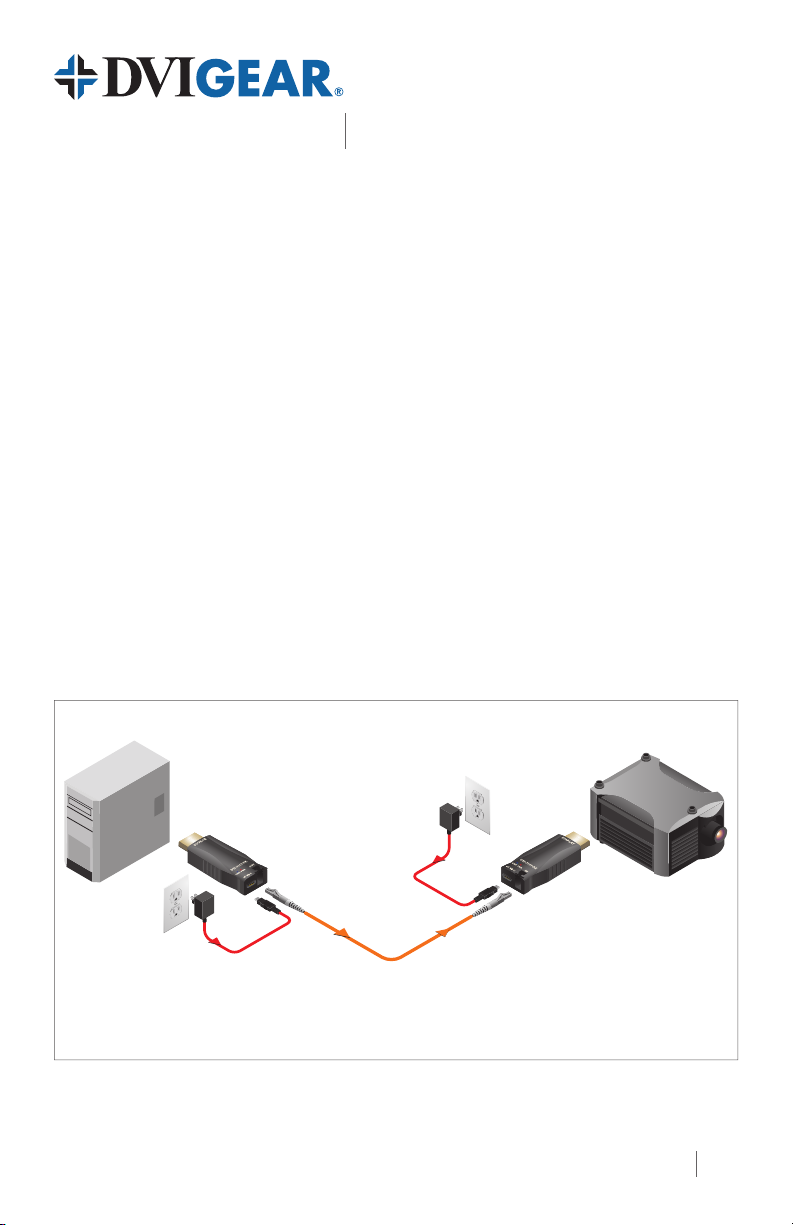
Typical Application
Source Device
(e.g. PC or Blu-ray Player)
+5 VDC
Power Adapter
DVI-7317-TX
+5 VDC
Power Adapter
*
(included)
One Single-Mode or Multi-Mode
DVI-7317 4K HDMI Fiber Optic Extender, 1x LC
DVIGear and DVIGear & Design are trademarks of DVIGear, Inc. and
may not be used without the prior written permission of DVIGear, Inc.
(included)
LC optical cable
Display Device
(e.g. Projector or Monitor)
DVI-7317-RX
*TX unit can be powered using an optional
USB adapter cable (p.n. DVI-7316-USB1)
1
Page 2
2
3
4
6
1
5
6
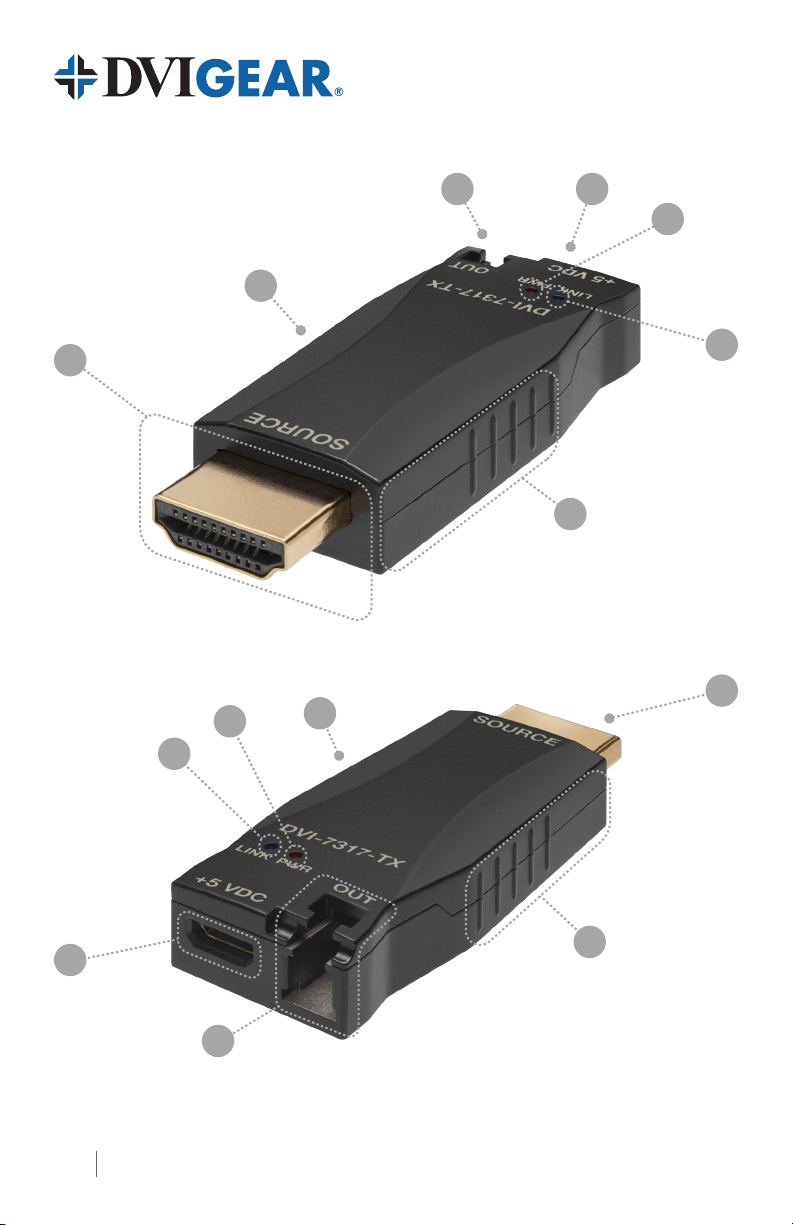
DVI-7317-TX Input View
1
4
5
6
3
6
2
DVI-7317-TX Output View
2
Page 3

4K HDMI Fiber Optic Extender, 1x LC
Quick Start Guide
DVI-7317
1. HDMI Connector
DVI-7317-TX connects to the source
DVI-7317-RX connects to the display or projector
2. Fiber Optic Connector 1x LC optical connector for ber optic cable
This port is used to power the unit. Connect the External AC Power
3. USB Connector
Adapter to this receptacle. Alternatively, it is also possible to power
the TX from a USB port that can supply adequate power.
4. Power LED Illuminates Red when DC power is applied
5. Link LED
6. Optional Heat Pad
Note 1: The DVI-7317-TX and DVI-7317-RX use the same type of enclosure and have the same connections.
Note 2 – WARNING: The metallic cases of the TX and RX can achieve relatively high temperatures in some
applications. Prior to operation, it is recommended that the included heat insulation pads be applied on the
sides of the units in the spaces shown. When handling the units, be certain to grip the units using these pads.
(2)
Illuminates Blue when optical link between the TX and RX
is operating properly
Apply the included heat insulation pads in the spaces shown.
(2)
Installation Instructions
This product consists of a DVI-7317-TX Transmitter Unit and a DVI-7317-RX Receiver Unit. These units
are interconnected by means of 1x LC-terminated optical cable, utilizing either 50/125μ Multi-Mode
ber or 9/125μ Single-Mode ber. For maximum cable lengths, please see the chart on page 4.
1.) Apply the included heat insulation pads on the sides of the TX and RX units in the spaces
shown. See the warning above.
2.) Connect the TX unit to the output port of the signal source (e.g. PC or Blu-ray player).
3.) Connect the RX unit to the input port of a destination device (e.g. display or projector).
(2)
4.) Each unit has one (1) Optical port. Connect an LC-terminated ber optic cable between
the TX unit and the RX unit.
5.) Connect the included External AC Power Adapters to the USB Micro-B port on the TX as
well as the RX. Then connect the power adapters to working outlets. Alternatively, it is
also possible to power the TX from a USB port that can supply adequate power. To do
this, connect the USB Micro-B port on the unit to the USB port on the source device using
an appropriate adapter cable (see below for details).
6.) Apply power to the display device, then apply power to the source device. A picture should
appear on the display within a few seconds.
Power Sources
The TX unit can be powered using either the supplied External AC Power Adapter or a functioning USB
port. In installations in which a USB port will be used to provide power to the TX, it is important to be
certain that adequate power is available on the USB port being used. Additionally, in this case, a USB
Type A Male to USB Micro-B Male Adapter Cable such as DVIGear’s DVI-7316-USB1 should be used.
3
Page 4

EDID and HDCP Communications
LASER RADIATION
On the ber optic link, the video component of the signal always travels in one direction, from TX to
RX. However, the extender employs wavelength-division multiplexing (WDM) to support additional
bidirectional signals over the same optical ber. This enables the device to support live EDID and
HDCP communications.
Maximum Cable Lengths
The maximum cable length supported by the extender pair will vary based on whether or not the
signal is HDCP encrypted as well as the type of ber being used. The HDCP encryption handshake
process occurs every two seconds and the response from the display must be received by the source
within a nite period of time. Regardless of the cable type being used, at lengths beyond 1,000ft.
(~300meters), the propagation delay as the signal transverses the optical ber is greater than the
response time allowed by the HDCP standard. For non-encrypted signals, however, much greater
extension distances are possible. See the chart below for more details.
HDCP Cable Length Recommended Cable Type
Yes
No > 1,800 ft. (~ 500 m) 50/125μ OM3 Multi-Mode Fiber
No > 2,600 ft. (~ 800 m) 50/125μ OM4 Multi-Mode Fiber
No
1,000 ft. (~ 300 m) All Fiber Types
> 1.2 miles (~ 2,000 m) 9/125μ Single-Mode Fiber
WARNING: Invisible Laser Radiation
Do not view directly with optical instruments or look into beam.
4 DVI-7317-QSG-01 / December.2017
© 2017 DVIGear, Inc.
All Rights Reserved
DVIGear
1059 Triad Court, Suite 8
Marietta, GA 30062
Toll Free: 888.463.9927
Tel: +1.770.421.6699
Fax: +1.770.234.4207
support@dvigear.com
www.dvigear.com
 Loading...