

Page 1
DVI-7313
DVI-7314
Quick Start Guide
Introduction
The DVI-7313 and DVI-7314 are high performance 4K Optical Extenders that transmit high resolution
DVI / HDMI signals over extreme distances using a single ber optic cable. These extenders support
HDMI v1.4 (non-HDCP) signals with resolutions up to 4K (4096x2160 / 30p) over cable distances
up to 1640 ft. (DVI-7313) and up to 1.2 miles (DVI-7314). Each extender set consists of an optical
transmitter module that converts the DVI / HDMI signals into light pulses for transmission over a single
strand of optical ber cable. An optical receiver module converts the light pulses back to a DVI / HDMI
signal for display on a monitor or projector. The transmitter unit includes an internal EDID memory
that can acquire and store the EDID from any display. The DVI-7313 supports Multi-Mode optical ber,
while the DVI-7314 supports both Multi-Mode and Single-Mode ber optic cable. These features make
the DVI-7313 and DVI-7314 the ideal future-proof choices for systems designers and integrators who
need to transmit high resolution DVI / HDMI signals over extreme distances.
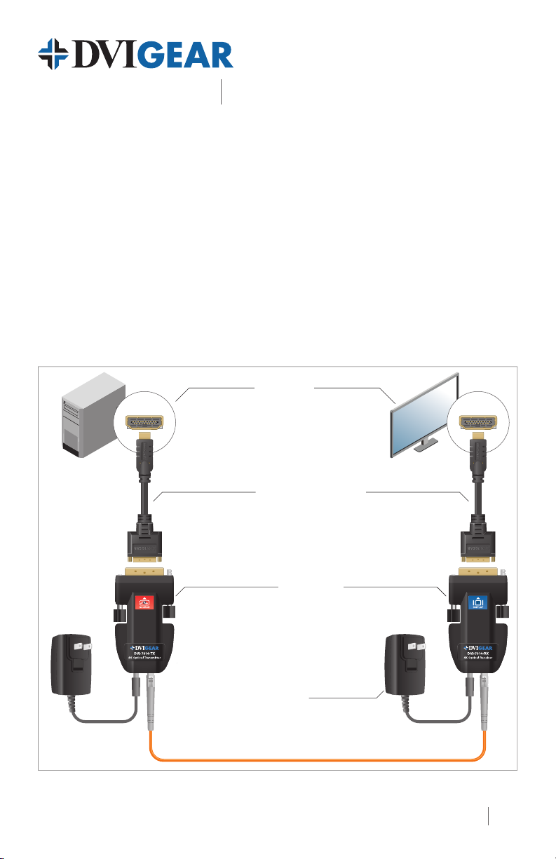
Typical Application
4K Fiber Optic Extenders, 1x LC
Optional
AC Power
Adapter
HDMI Port
DVI-8511c
Adapter Cable
(included)
Transmitter
1x LC Optical Cable
DVI-7313 / DVI-7314 4K Fiber Optic Extenders, 1x LC
HDMI Port
DVI-8511c
Adapter Cable
(included)
Receiver
AC Power
Adapter
(included)
1
Page 2
2a
1
3
4
5
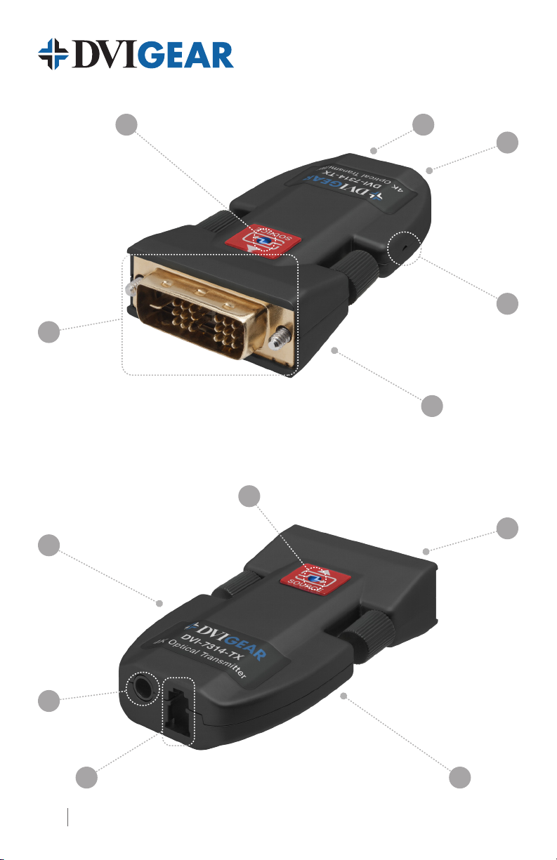
DVI-7314-TX Front View
2a
5
4
3
DVI-7314-TX Rear View
2b
1
2b
2
Page 3

4K Fiber Optic Extenders, 1x LC
Quick Start Guide
DVI-7313
DVI-7314
1. DVI Connector
2a. Top LED
2b. Bottom (Power) LED Illuminates Red when DC power is applied
3. Fiber Optic Connector 1x LC optical connector for ber optic cable
4. DC IN Connector Connect the External AC Power Adapter to this receptacle
5. Learn EDID Button (TX) Use a stylus to actuate this switch following the procedure on page 4
Note: The DVI-7313 / DVI-7314 Transmitter units and Receiver units use the same type of
enclosure and have the same connections.
DVI-7313-TX / DVI-7314-TX connects to source;
DVI-7313-RX / DVI-7314-RX connects to display
Tx: Flashes Blue momentarily when EDID has been read successfully;
Rx: Illuminates Blue when connected to a working display
Installation Instructions
This product consists of a DVI-7313 / DVI-7314 Transmitter Unit and a DVI-7313 / DVI-7314 Receiver
Unit. These units are interconnected by means of a single-channel LC optical cable, utilizing either
50/125μ Multi-Mode ber or 9/125μ Single-Mode ber (DVI-7314). The DVI-7314 is also capable of
using Multi-Mode ber. For maximum cable lengths, please see the chart on page 4.
1.) Learn the EDID from the destination device (see instructions on page 4).
2.) Connect the Transmitter Unit to the output port of the signal source (e.g. PC). For a DVI source,
simply connect the Tx to the DVI output. For an HDMI source, use the included DVI female to
HDMI male adapter cable.
3.) Connect the Receiver Unit to the input port of a destination device (e.g. digital display). For
a DVI destination, simply connect the Rx to the DVI input. For an HDMI destination, use the
included DVI female to HDMI male adapter cable.
4.) Each unit has one (1) Optical port. Connect an LC-terminated ber optic cable between the
Transmitter Unit and the Receiver Unit.
5.) Connect the External AC Power Adapter to the power input jack on the Receiver Unit.
6.) Apply power to the display device, then apply power to the source device. A picture should appear
on the display within a few seconds.
Power Sources
The Receiver Unit must be powered from the supplied External AC Power Adapter. It cannot be
powered from the connected display device. However, the Transmitter Unit can draw power from the
source device in most applications. In the event that the source cannot provide adequate power for
the transmitter, an optional External AC Power Supply is available (part number DVI-7210-PS).
3
Page 4

Learn EDID Button
LASER RADIATION
Insert a stylus to press the Learn EDID Button
Instructions for Learning the EDID from a Display
1.) Apply power to the display.
2.) Connect the DVI-7313 / DVI-7314 Transmitter unit to the display’s DVI or HDMI input port.
3.) Connect the External AC Power Adapter to the Transmitter unit.
4.) Press the Learn EDID button (page 2 - #5) by manually inserting a stylus into the side of the
Transmitter unit. If the EDID is properly read, the BLUE Indicator LED (page 2 - #2a) should
illuminate once.
5.) Remove the External AC Power Adapter from the Transmitter unit.
6.) Disconnect the Transmitter unit from the display and connect it to the DVI or HDMI signal
source device.
7.) Follow the Installation Instructions (3-6) listed on page 3.
Maximum Cable Lengths
Model Cable Length Recommended Cable Type
DVI-7313
DVI-7313 > 1,000 ft. ( > 300 m ) 50/125μ OM3 Multi-Mode Fiber
DVI-7314 > 1.2 mi. ( > 2000 m ) 9/125μ Single-Mode Fiber
DVI-7314 > 1,640 ft. ( > 500 m ) 50/125μ OM4 Multi-Mode Fiber
DVI-7314
WARNING: Invisible Laser Radiation
Do not view directly with optical instruments or look into beam.
> 1,640 ft. ( > 500 m ) 50/125μ OM4 Multi-Mode Fiber
> 1,000 ft. ( > 300 m ) 50/125μ OM3 Multi-Mode Fiber
DVIGear
1059 Triad Court, Suite 8,
Marietta, GA 30062
Toll Free: 888.463.9927
Tel: 770.421.6699
Fax: 770.234.4207
support@dvigear.com
DVI-7313_DVI-7314-QSG-01 / December.2014
www.dvigear.com4
 Loading...