

Page 1
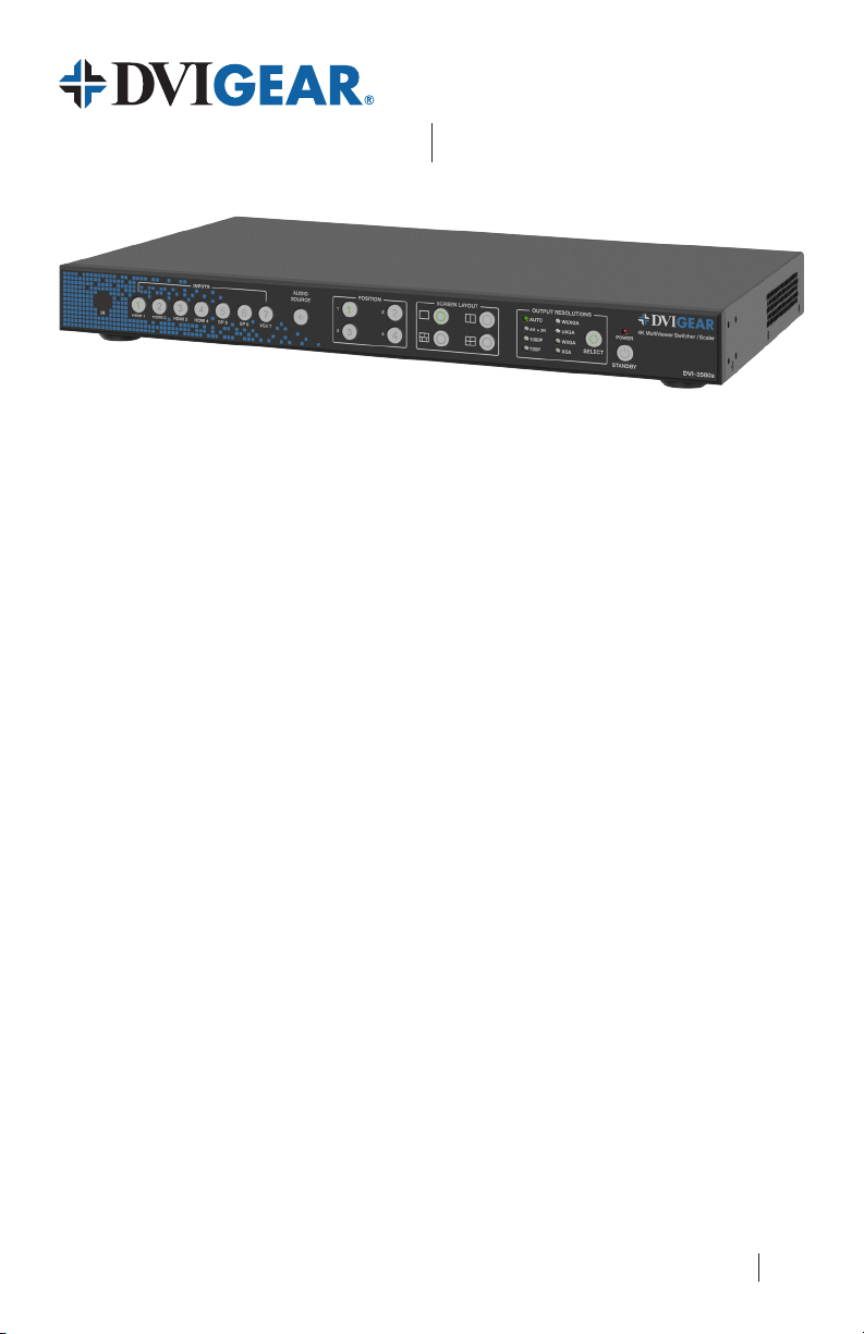
DVI-3580a
4K MultiViewer
Quick Start Guide
Introduction
Presentation Powerhouse – The DVI-3580a is a high-performance 4K MultiViewer, Presentation
Switcher and Scaler. This unit is an ideal solution for system designers and facility managers facing
uncertain requirements from presenters that need AV signal distribution for a diverse range of source
devices, resolutions and signal formats. The DVI-3580a overcomes these challenges through a rich
array of input connections that supports all popular AV input signal formats, a range of user-selectable
output resolutions and innovative MultiViewer capabilities. These features provide the power
and exibility needed to adapt to the ever-changing demands of presentation rooms, classrooms,
auditoriums, conference rooms, houses of worship, and other media-rich AV environments.
Versatile Video Capabilities – This powerful presentation switcher accepts up to seven (7) video
inputs: 4x HDMI (or DVI), 2x DisplayPort and 1x RGB/YPbPr Analog (VGA). The unit supports a broad
range of input signal formats and resolutions up to 4K /60p. A powerful internal scaling engine
provides a range of user-selectable output resolutions up to 3840x2160/30p, as well as seamless
switching
and 1x HDBaseT™. The HDBaseT output is POH (Power over HDBaseT) compliant, so a compatible
receiver unit may be remotely powered from the DVI-3580a unit over the HDBaseT link. The
MultiViewer function can simultaneously display up to 4x video signals with resolutions up to 4K,
which are displayed in seven possible layouts: Single, Double, Triple, Quad 1, Quad 2, Quad 3, or
Quad 4. Any input signal can be displayed in any MultiViewer window.
Advanced Audio Routing – The DVI-3580a features audio embedding as well as de-embedded
audio outputs. Each video input is coupled with an analog stereo audio input connection. The unit
includes three audio outputs: HDMI / HDBaseT embedded audio, 8-channel (7.1) analog audio, and
TOSLINK optical audio. User-adjustable lip-sync correction is provided.
Total Control – The DVI-3580a may be controlled via a variety of options, including LAN (built-in
Web GUI or Telnet), RS-232, IR Remote Control, and Front Panel selections. The Web GUI increases
ease of setup and support through many features, including powerful EDID management capabilities.
This allows integrators to select a factory installed EDID, learn the EDID from a connected display,
upload EDID les into 7x custom memory slots, or download EDID les from the unit. These powerful
features allow the unit to be seamlessly integrated into any professional AV system.
Note 1: Seamless switching is only available in Single Window Layout Mode.
(1)
of input signals. The selected input signal is routed to two mirrored outputs, 1x HDMI
Switcher / Scaler
HDBaseT™ is a trademark of the HDBaseT Alliance.
DVIGear and DVIGear & Design are trademarks of DVIGear, Inc. and
may not be used without the prior written permission of DVIGear, Inc.
1
Page 2
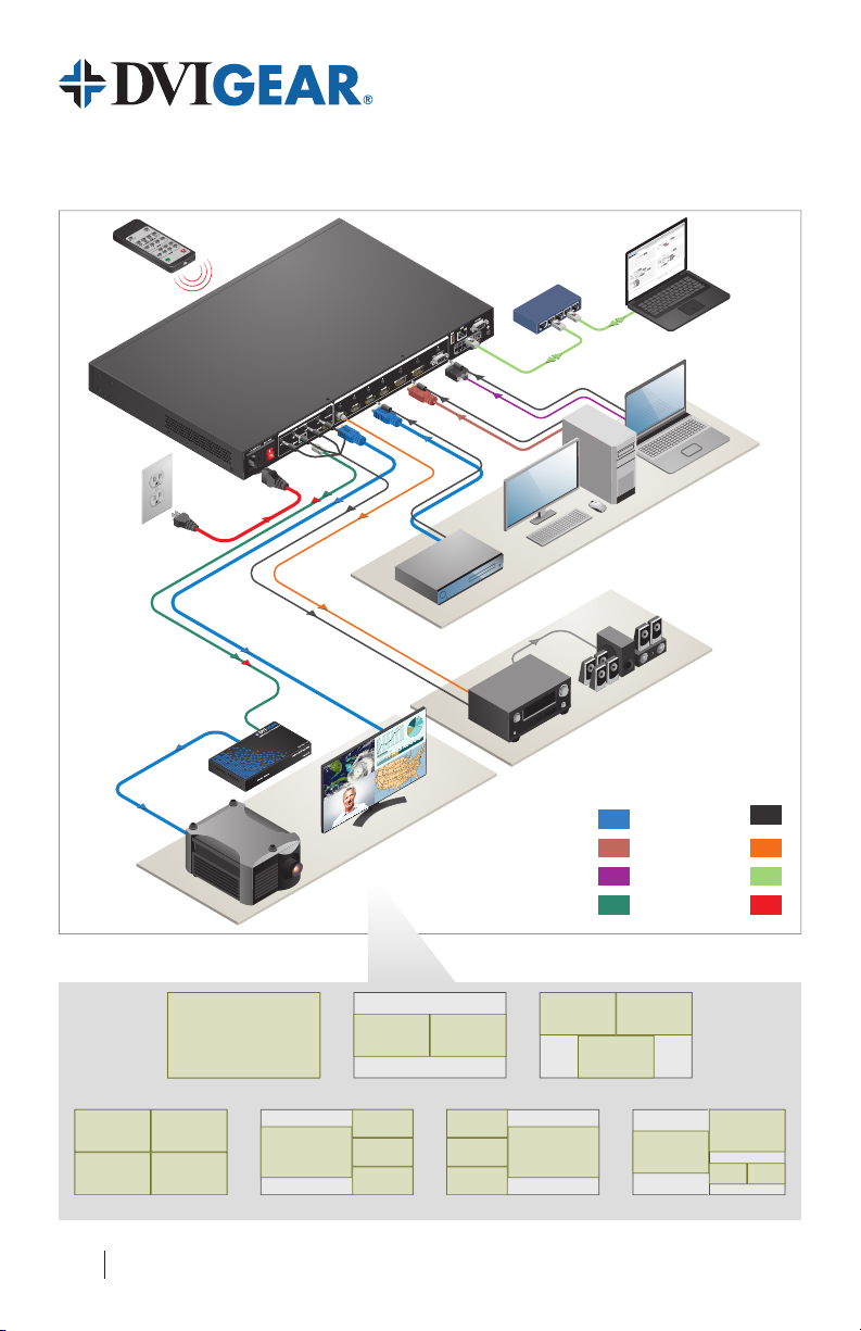
System Application
Display Devices
and 8-Channel (7.1) Speakers
IR Remote Control
HDBaseT with Remote
Power (POH) from DVI-3580a
to HDBaseT Receiver
DVI-7520-RX
(HDBaseT Receiver)
DVI-3580a
DVIGear SHR™ HDMI Cable
Source Devices
DVIGear HR™ DP Cable
VGA
HDBaseT
EDID
NetworkGeneral
192.168.100.100/general.ht x
/
Submit
192.168.100.100/general.html/192.168.100.100/general.html
/
DVIGEAR
Device Info
Name (max 20 characters):
Model Number: DVI-3580a
Serial Number: DVI-150100
Unit Firmware Version: DVI 2.0.0.P_CL1116
GUI Version: 2.10_CL1092
Submit
Submit
Run Time: 8:22:8 (Days : Hours : Mins)
Submit
4
Normal
W4W3W2W1
W4W3W2W1
Single
3
Video
Normal
Submit
2
Screen Layout
Normal
Video Input Source:
1
Auto
Aspect Ratio:
Normal
Submit
Attention: This setting will take effect after reboot)
(
Output Resolution
Submit
Auto-Priority
Submit
On
HDMI OUT
Submit
© 2015 DVIGear, Inc. | +1.770.421.6699 | support@dvigear.com | Contact Support
Input HDCP
On
VGA Auto Adjust
Video OSD
Audio Receiver
TOSLINK Optical Audio
4K MultiViewer Switcher / Scaler
Submit
0
Power Saving (0 - 60 min.)Power
Submit
System
Reset
On
Restart Device
Submit
Reset to Factory Defaults
5
1
Submit
Submit
Auto
Audio
0
Auto
Audio Input Source Audio Volume (0 - 10)
Auto
Submit
Audio Input Config:
Auto
Off
Auto
1 2 3
Off
Auto
4 5 6
Submit
All Audio Mute Audio Delay (0 - 10)
On
HDMI / HDBT Output Audio Mute
Audio OSD
DVI-3580a
Control Laptop
Analog Audio
LAN
Power
MultiViewer Layout Options
1
Single
1 2
3 4
Quad 1
2
1
Quad 2
1 2
Double
2
3
4
1 2
3
Triple
2
3
4
1
Quad 3
1
2
3 4
Quad 4
Page 3

4K MultiViewer Switcher / Scaler
DVI-3580a
Quick Start Guide
Installation
For complete operating instructions,
please refer to the User Manual.
1.) Rack Mount Ears and Removable Feet:
Add or remove these accessories as needed.
2.) Video Sources and Destinations: Connect each
video source device to the HDMI, DisplayPort or VGA inputs on the rear of the DVI-3580a as needed.
Next, connect the displays or downstream devices to the HDMI output and/or the HDBaseT output.
The HDBaseT output only supports extension of audio, video, and POH. The RS-232, LAN, and IR
signals cannot be extended over the link. For best results, DVIGear recommends using CAT-6A F/UTP
(500 MHz) 23AWG high-grade cable or better for the HDBaseT link. See the warning below.
3.) Audio Sources and Destinations: Connect any external audio sources to the 3.5mm mini-jacks
accompanying the appropriate video signals as needed. Next, connect any downstream audio
devices to the appropriate audio outputs as needed.
4.) Control Connections: The unit may be controlled via a variety of options, including LAN (built-in
Web GUI or Telnet), RS-232, IR Remote Control, and Front Panel selections. The most intuitive,
versatile control method is the built-in Web GUI (see page 7).
To control the unit via the LAN port, connect it to the network or directly to a PC using a standard
(straight-through) LAN cable. Set the IP address of the control PC to be within the same subnet
as the unit. Next, open a web browser and input the IP address of the unit. By default, the
unit has an IP address of 192.168.100.100 and DHCP Mode disabled. To view the current IP
address at any time, press and hold the Audio Source Button on the front panel or IR remote for 5
seconds and the current IP will be displayed on the screen.
To control the unit via the RS-232 port, connect to the unit using a straight-through cable.
Default values: baud rate: 9600; data bits: 8; stop bits: 1; parity: none; ow control: none.
(2)
5.) Power: First, supply power to the destination devices.
Next, supply power to the DVI-3580a. To do this, plug the AC Power Cord into the receptacle on
the unit and then into an outlet. Switch the unit ON using the master switch on the rear of the
unit. This switch, along with the red power LED on the front panel, will remain illuminated when
power is supplied to the unit and the master switch is turned ON. The unit may need to be toggled
out of standby mode. When the unit is in standby, the standby button on the front panel will light up
green. Pressing this button will bring the unit out of standby.
After the unit is powered ON and is out of standby mode, supply power to the source devices.
Note 2 – WARNING: The HDBaseT port is designed to connect to compatible HDBaseT products only (e.g. DVIGear's DVI7520-RX). Do not connect any device to the HDBaseT port of this product unless you have veried that it is compatible.
Do not connect any HDBaseT device to the LAN port of the DVI-3580a. Connecting incompatible devices may cause harm
to the devices. Please consult technical support with any questions concerning product interoperability.
Please use the preferred cable termination scheme (T568B) for all HDBaseT connections throughout the installation
(see the User Manual for more information). It is typical for HDBaseT receivers to operate at high temperatures.
Care must be taken to ensure airow through the Rx unit is not restricted in any way.
3
Page 4

Front Panel Layout
1. IR Receiver Window Receives IR signals from the IR Remote Control.
2. Input Buttons
3. Audio Source Button
4. Window Position Buttons
1
9
10
Press buttons 1-7 to select the video or audio inputs. The indicators
show the status of the input selections.
Press this button and then press one of the input buttons (1-7) to select the
audio input. Use the Web GUI or RS-232 / IP commands for full control.
These buttons are used to assign video inputs to certain MultiViewer
window positions (see page 6).
2
1211
43
Rear Panel Layout
9. 100~240 VAC Input Connect the included AC power cord to this receptacle.
10. Master Power Switch Turns the device ON / OFF.
11. 7.1 Analog Audio Out Connect to a multimedia system. See the User Manual for channel assignments.
12. TOSLINK Audio Output Connect to the optical input port of an audio amplier.
13. HDBaseT Output Connect to an HDBaseT device (e.g. DVI-7520-RX). See the warning on pg. 3.
14. HDMI Output Connect to an HDMI display device.
15. HDMI Inputs Connect to the HDMI source devices.
4
151413
Page 5

4K MultiViewer Switcher / Scaler
Front Panel Layout
DVI-3580a
Quick Start Guide
5. Screen Layout Buttons
6. Output Resolution Button
and LEDs
7. Power Indicator LED Lights when power is applied and the master power switch is ON.
8. Standby Button
Select from one of seven different MultiViewer layouts:
Single, Double, Triple, Quad 1, Quad 2, Quad 3, or Quad 4.
Press this button to cycle through and select the output resolution. The LED of
the selected resolution will light up. See pg. 8 for available output resolutions.
Toggles the unit between standby and normal power modes. The green
indicator lights up when in standby mode.
8765
21201916
221817
Rear Panel Layout
16. Analog Audio Inputs Connect to the audio source devices using 3.5mm mini-stereo cables.
17. DP Inputs Connect to the DisplayPort source devices.
18. VGA Input Connect to a source using an HD-15 cable or a YPbPr to VGA adapter cable.
19. USB Connector This port is reserved for service personnel.
20. LAN Connector Connect to a network or PC to control the unit. See the warning on pg. 3.
21. RS-232 Connector Connect to an RS-232 device. See the command list in the User Manual.
22. Ground Screw Attach the unit to an appropriate electrical ground. Consult an electrician.
5
Page 6

Switching Video Inputs
1.) Single Window Layout Mode: Use the Single window button ( ) on the front panel or on the IR
remote to set the unit to Single Window Layout Mode. The button indicator for window position 1
and the indicator for the selected input will light up. By default, HDMI 1 is assigned to window 1.
2.) Select a Video Input: Press an input button on the front panel or on the IR remote.
3.) Front Panel Status: After the seamless switch has been performed, the selected input indicator
will be lit. Please note that seamless switching is only available in Single Window Layout Mode.
MultiViewer Setup Using the Front Panel or IR Remote
1.) Select a MultiViewer Window Layout: To display multiple inputs on the screen simultaneously,
press the Double ( ), Triple ( ), or Quad ( ) window buttons on the front panel or on the IR
remote. This will set the output of the unit to display two, three, or four windows. On the front
panel, Window Position Buttons 1, 2, 3, and 4 will light up depending on which windows are active.
To access Quad Layouts 1-4 (see page 2), rst press the Quad ( ) window button. Once the unit
is set to Quad Mode, it is possible to cycle through Quad Layouts 1-4 by pressing the Quad button
again. Every press of the button will advance the unit to the next layout in the sequence.
2.) MultiViewer Window Layouts: The video output will now display multiple input signals in up to
4 separate windows. When using the front panel or IR remote, the video switching is performed
independently for each layout. Any video switching done in one layout will be stored for that layout
and will not affect the others (see the User Manual for more details). Any input signal can be
displayed in any window. By default, HDMI inputs 1-4 are assigned to window positions 1-4.
3.) Assigning an Input to a Window: First, press an input button (1-7) on the front panel or on the
IR remote. Depending on which window layout is active, the video position 1, 2, 3, and 4 button
indicators will blink, showing which buttons can be selected. In this state, a selection must be
made within 5 seconds or the unit will return to normal. Next, press one of the window position
buttons on the front panel or on the IR remote to assign the selected input to that window. Other
inputs can be assigned to the other window positions using the same method.
4.) Front Panel Status: After the layout selection and window position assignments have been
performed, the input indicators will be off and the front panel status will return to normal.
Changing Output Resolutions
The DVI-3580a includes 2x mirrored outputs: 1x HDMI and 1x HDBaseT. These outputs support several
user-selectable resolutions (see page 8). Use any of the control methods to select the resolution.
To change output resolution using the front panel or IR remote, press the Output Resolution Selection
Button (Resolution on the IR remote). The unit will advance the selection to the next output resolution
in the sequence. Once the selection is complete, the corresponding LED will light up continuously.
The switching sequence is as follows:
(3)
Auto
4K x 2K 1080p 720p WUXGA UXGA WXGA XGA Auto
Note 3: When the output is set to Auto, the unit will read the EDID information from the display device and select
the available output resolution that best matches the native timing of the display. Use the Web GUI or RS-232 /
IP commands to assign EDID priority to the HDMI output or the HDBaseT output.
6
(3)
Page 7

4K MultiViewer Switcher / Scaler
DVI-3580a
Quick Start Guide
Audio Capabilities
The unit supports audio embedding and de-embedded audio. It includes multiple audio output options.
The IR remote includes a button to Mute / Un-Mute the output audio. See the User Manual for full details.
HDCP Management
The DVI-3580a is HDCP v1.4 compliant. If protected content is sent to a non-compliant display, then
a full eld red screen will be shown on-screen on a per window basis. Additionally, the unit also
includes an Input HDCP setting, which can be used to prevent the HDCP acknowledgment from being
sent over the HDMI and DP inputs. This feature is useful for cases in which the source device is
incorrectly sending an HDCP encrypted signal. When this is set to Off, the source devices will view
the DVI-3580a as a non-HDCP device and operate accordingly. Content that would not normally be
copy-protected such as a computer desktop will be sent without HDCP encryption; however, as usual,
protected content (e.g. from a Blu-ray player) will not be sent.
Control Options
The unit may be controlled via several options: LAN (built-in Web GUI or Telnet), RS-232, IR Remote
Control, and Front Panel selections. The most intuitive, versatile control method is the Web GUI. To
access the Web GUI, connect to the unit using the instructions on page 3. See the User Manual for
full details on operating the Web GUI as well as the other control options. The Web GUI includes the
functions below. See the User Manual for detailed explanations on all the functions of the Web GUI.
General Tab: Use this to control or access device info, power settings, video settings, and audio settings.
Network Tab: Use this to control or access the communication settings of the unit such as the MAC
Address, DHCP Mode, IP address, Subnet Mask, Gateway, DNS, Baud Rate, Socket, and Port Number.
EDID Tab: Use this to perform Advanced EDID Management functions.
192.168.100.100/general.ht x
192.168.100.100/general.html192.168.100.100/general.html
Device Info
Name (max 20 characters):
Model Number: DVI-3580a
Serial Number: DVI-150100
Unit Firmware Version: DVI 2.0.0.P_CL1116
GUI Version: 2.10_CL1092
Run Time: 8:22:8 (Days : Hours : Mins)
DVIGEAR
Video
Submit
SingleScreen Layout
Video Input Source:
Aspect Ratio:
Output Resolution
Auto-Priority (Attention: This setting will take effect after reboot)
HDMI OUT
Input HDCP
VGA Auto Adjust
Video OSD
Auto
Submit
On
On
Submit
Submit
Submit
4321
W4W3W2W1
W4W3W2W1
Submit
EDIDNetworkGeneral
System
Submit
On
Power Saving (0 - 60 min.)Power
Restart Device
Reset to Factory Defaults
Audio
Audio Input Source Audio Volume (0 - 10)
Submit
Submit
NormalNormalNormalNormal
© 2015 DVIGear, Inc. | +1.770.421.6699 | support@dvigear.com | Contact Support
Audio Input Config:
1 2 3
4 5 6
All Audio Mute Audio Delay (0 - 10)
Off
HDMI / HDBT Output Audio Mute
Audio OSD
On
4K MultiViewer Switcher / Scaler
Submit
Reset
AutoAutoAuto
AutoAutoAuto
0
Submit
5
Submit
Submit
0
Submit
Off
Submit
1
Submit
DVI-3580a
7
Page 8

Supported Input Resolutions (Partial)
LASER RADIATION
(4)
Input Resolution Scan Format Vertical Rate (Hz)
640x480 Progressive 60, 72, 75, 85
720x576 Progressive 50, 100
800x600 Progressive 56, 60, 72, 75, 85
1024x768 Progressive 60, 70, 75, 85
1280x720 Progressive 50, 60
1280x768 Progressive 60, 75, 80, 85
1280x960 Progressive 60, 85
1280x1024 Progressive 60, 75, 85
1366x768 Progressive 50, 60
1600x900 Progressive 60
1600x1200 Progressive 60, 65, 70, 75
1920x1080 Interlaced 25, 30, 50, 60
1920x1080 Progressive 24, 25, 30, 50, 60
1920x1200 Progressive 60
1920x1440
(5)
Progressive 60
3840x2160 Progressive 24, 30, 60
4096x2160 Progressive 24
Supported Output Resolutions
(7)
Output Resolution Scan Format Vertical Rate (Hz)
1024x768 (XGA) Progressive 60
1280x800 (WXGA) Progressive 60
1600x1200 (UXGA) Progressive 60
1920x1200 (WUXGA) Progressive 60
1280x720 (720p) Progressive 60
1920x1080 (1080p) Progressive 60
3840x2160 (4K x 2K) Progressive 30
(6)
Package Contents
1x DVI-3580a 4K MultiViewer Switcher / Scaler
1x External AC Power Cord
1x IR Remote Control Unit
1x Quick Start Guide
Note 4: For a broader list of supported input resolutions, please see the User Manual or the DVIGear website.
Note 5: The VGA input is limited to 1920x1440 resolution.
Note 6: The DisplayPort inputs support up to 3840x2160 /60p RGB 4:4:4.
The HDMI inputs support up to 3840x2160 /30p RGB 4:4:4 and
3840x2160 /60p YPbPr 4:2:0.
Note 7: Both HDMI and HDBaseT outputs always provide RGB 4:4:4 color
regardless of selected input signal or selected output resolution.
WARNING: Invisible Laser Radiation
Do not view directly with optical instruments or look into beam.
8
DVI-3580a-QSG-02 / April.2017
1x USB Flash Drive Loaded with User Manual
1x Set of Rack Mount Ears
8x Screws to attach Rack Mount Ears
DVIGear
1059 Triad Court, Suite 8
Marietta, GA 30062
Toll Free: 888.463.9927
Tel: +1.770.421.6699
Fax: +1.770.234.4207
© 2016, 2017 DVIGear, Inc.
All Rights Reserved
support@dvigear.com
www.dvigear.com
 Loading...