

Page 1
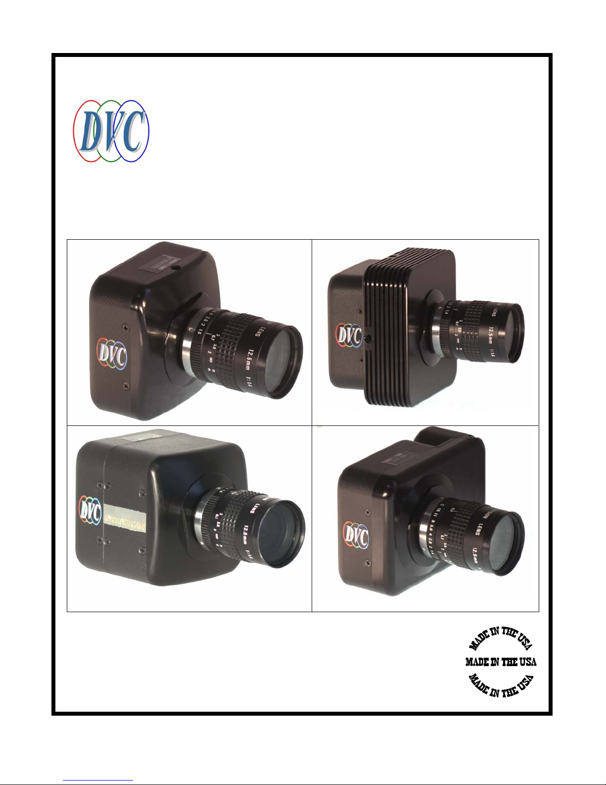
TECHNICAL MANUAL FOR
Manual Number: 86-1412-05
Release Date: January 1, 2003
DVC-1412A CAMERAS
DVC Company
10200 Highway 290 West
Austin, Texas 78736
Phone: (512) 301-9564
Fax: (512) 288-2961
E-Mail: [email protected]
WWW: http://www.dvcco.com
Page 2

TABLE OF CONTENTS
TABLE OF CONTENTS ....................................................................................................................................... ii
1 INTRODUCTION ...............................................................................................................................................1
2 INITIAL INSPECTION......................................................................................................................................2
2.1 UNPACKING AND RECEIVING................................................................................................................2
2.2 EQUIPMENT SUPPLIED (LVDS SYSTEM)..................................................................................................3
2.3 EQUIPMENT SUPPLIED (FIREWIRE SYSTEM)............................................................................................4
2.4 EQUIPMENT SUPPLIED (CAMERALINK SYSTEM)......................................................................................5
2.5 OPTIONAL ITEMS.......................................................................................................................................6
2.6 CAMERA POWER SUPPLY........................................................................................................................6
2.6.1 INTERNATIONAL APPLICATIONS .....................................................................................................6
3 MAINTENANCE.................................................................................................................................................7
3.1 IMPORTANT WARRANTY INFORMATION............................................................................................7
3.2 CLEANING THE LENS.......................................................................................................................................8
3.3 CLEANING THE INFRA-RED FILTER..................................................................................................................8
3.3.1 What must I do before cleaning the infra-red filter? .............................................................................8
3.3.2 What if the contamination includes a smudge?......................................................................................8
3.3.3 What if the contamination is only a few dust particles? ........................................................................8
4 CAMERA SPECIFICATIONS ........................................................................................................................13
4.1 OPTICAL ....................................................................................................................................................13
4.2 DIGITAL VIDEO OUTPUT .......................................................................................................................14
4.2.1 12 Bit RS-422/RS-644 (LVDS / FireWire) ...........................................................................................14
4.3 1412 INTENSICAM....................................................................................................................................14
.................................................................................................................................................................................14
4.4 CAMERA CONTROL.................................................................................................................................15
4.5 ELECTRICAL.............................................................................................................................................15
4.6 MECHANICAL: STANDARD LVDS/FIREWIRE/CAMERALINK CAMERAS....................................15
4.7 MECHANICAL : COOLED CAMERAS ...................................................................................................15
4.8 MECHANICAL : INTENSICAM...............................................................................................................15
5 CAMERA FUNCTIONAL DESCRIPTION...................................................................................................17
5.1 BLOCK DIAGRAM....................................................................................................................................17
5.2 CCD AND VIDEO BOARD........................................................................................................................17
5.2.1 CCD Sensor .........................................................................................................................................17
5.2.2 Video Processing .................................................................................................................................18
5.2.3 Video Digitization................................................................................................................................18
5.2.4 Voltage Regulation ..............................................................................................................................19
5.2.5 Timing..................................................................................................................................................19
5.3 DIGITAL I/O BOARD ................................................................................................................................19
5.3.1 LVDS Version: TTL to LVDS Drivers..................................................................................................19
5.3.2 Fire Wire Version ................................................................................................................................19
5.3.3 CameraLink Version............................................................................................................................19
6 INSTALLATION...............................................................................................................................................20
7 MODES OF OPERATION...............................................................................................................................20
7.1 NORMAL MODE .......................................................................................................................................20
7.2 HIGH SPEED SHUTTER............................................................................................................................21
7.2.1 Setting The Exposure Duration............................................................................................................21
7.2.2 Strobe...................................................................................................................................................21
ii
Page 3

7.2.3
Reset & Shutter ....................................................................................................................................22
7.2.4 Reset Modes.........................................................................................................................................24
7.3 N FRAME INTEGRATION........................................................................................................................26
7.3.1 Reset Operation in N-Frame Integration Mode...................................................................................26
7.4 ULT: ULTRA-LONG-TERM EXPOSURE ................................................................................................26
7.5 PULSE DRIVEN EXPOSURE....................................................................................................................27
7.6 BINNING ....................................................................................................................................................28
7.6.1 Binning and Shutter:............................................................................................................................31
7.6.2 Binning and Bayer Pattern Color Filter Arrays ..................................................................................31
7.7 SUB-ARRAY / REGION OF INTEREST (ROI )...................................................................................................32
7.7.1 Functional Description........................................................................................................................32
7.7.2 Advantages...........................................................................................................................................33
7.7.3 Disadvantages......................................................................................................................................33
7.7.4 What can be done to overcome this disadvantage? .............................................................................33
7.7.5 What applications should ROI be used for? ........................................................................................33
7.7.6 ROI Commands....................................................................................................................................33
7.8 SLOW SCAN ..............................................................................................................................................34
7.9 INTENSICAM-1412 ...................................................................................................................................35
7.9.1 Introduction .........................................................................................................................................35
7.9.2 Functional Description........................................................................................................................35
7.9.3 Spectral Response................................................................................................................................36
7.9.4 Intensicam & DCView......................................................................................................................37
7.10 MULTI-SPECTRAL OPTION....................................................................................................................38
7.10.1 Software issues.....................................................................................................................................38
7.10.2 Spectral Response................................................................................................................................40
7.10.3 Module Removal & Change of Filters .................................................................................................41
8 APPLICATION NOTES...................................................................................................................................49
8.1 BAYER FILTER DECODING ALGORITHM ...........................................................................................49
8.1.1 Introduction .........................................................................................................................................49
8.1.2 Color Pixel Processing ........................................................................................................................49
8.1.3 White Balance......................................................................................................................................49
8.1.4 Gamma Correction ..............................................................................................................................51
8.1.5 Color Coding .......................................................................................................................................51
8.1.6 Suggested Algorithm............................................................................................................................51
9 SERIAL COMMAND INTERFACE DEFINITION FOR DVC-1412ACAMERAS (LVDS AND
CAMERALINK CAMERAS)...................................................................................................................................52
9.1 INTRODUCTION.......................................................................................................................................52
9.2 COMMUNICATION PROTOCOL.............................................................................................................52
9.3 CAMERA CONTROLS ..............................................................................................................................52
9.3.1 Gain .....................................................................................................................................................52
9.3.2 Offset (or black level) ..........................................................................................................................53
9.3.3 Exposure ..............................................................................................................................................53
9.3.4 Mode Summary ....................................................................................................................................53
9.4 SPECIAL COMMANDS.............................................................................................................................56
9.4.1 Intensifier Control ...............................................................................................................................57
9.4.2 Notes on Intensifier Operation.............................................................................................................57
9.4.3 Notes on Wheel Commands .................................................................................................................59
9.5 COMMAND SUMMARY...........................................................................................................................60
10 INFORMATION AND SUPPORT RESOURCES.........................................................................................61
11 APPENDIX.........................................................................................................................................................62
11.1 APPENDIX A: MECHANICAL DIMENSIONS DIAGRAM ....................................................................62
11.2 APPENDIX B: CABLE DRAWINGS.........................................................................................................69
iii
Page 4

11.3
APPENDIX C: DVC-1412 CAMERA CONNECTORS .............................................................................73
11.3.1 Auxiliary Connector.............................................................................................................................74
12 WARRANTY AND AFTER-SALES SERVICE.............................................................................................77
13 COPYRIGHT INFORMATION......................................................................................................................78
iv
Page 5

LIST OF FIGURES
Figure 2.2-1: DVC-1412 Camera and adjustment wrench ............................................................................................3
Figure 2.2-2: Linear regulated power supply.................................................................................................................3
Figure 2.2-3: PixeLYNX board.....................................................................................................................................3
Figure 2.2-4:US version of line cord with IEC320 receptacle.......................................................................................3
Figure 2.2-5: DVC distribution CD-ROM.....................................................................................................................3
Figure 2.2-6: 10ft. interface cable, with 18” RS232 pigtail...........................................................................................3
Figure 2.3-1: DVC-1412 Camera and adjustment wrench ............................................................................................4
Figure 2.3-2: Linear regulated power supply.................................................................................................................4
Figure 2.3-3: Firewire cable (actual color may vary) ....................................................................................................4
Figure 2.3-4:US version of line cord with IEC320 receptacle.......................................................................................4
Figure 2.33-2.3-5: DVC distribution CD-ROM ............................................................................................................4
Figure 2.4-1: DVC-1412 Camera and adjustment wrench ............................................................................................5
Figure 2.4-2: Linear regulated power supply.................................................................................................................5
Figure 2.4-3: CameraLink cable (actual color may vary).............................................................................................5
Figure 2.4-4:US version of line cord with IEC320 receptacle.......................................................................................5
Figure 2.4-5: DVC distribution CD-ROM.....................................................................................................................5
Figure 2.4-6: CameraLink board ...................................................................................................................................5
Figure 2.6-1: Bottom view of power supply showing voltage selection switch (115V)................................................6
Figure 2.6-2: Bottom view of power supply showing voltage selection switch (220V)................................................6
Figure 2.6-3: IEC line cord with Euro-style plug ..........................................................................................................6
Figure 2.6-4: IEC line cord with UK-style plug ............................................................................................................6
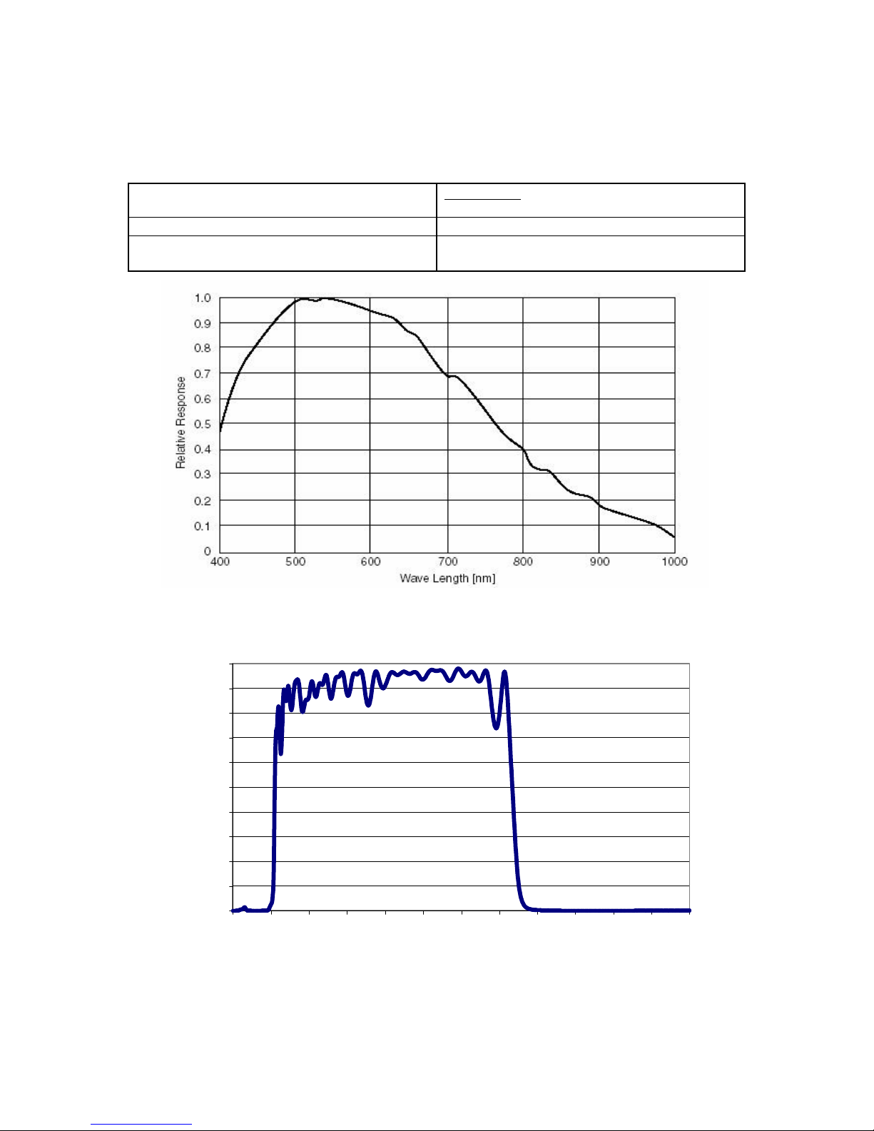
Figure 4.1-1: Monochrome camera spectral response.................................................................................................13
Figure 4.1-2: IR Filter Characteristics .........................................................................................................................13
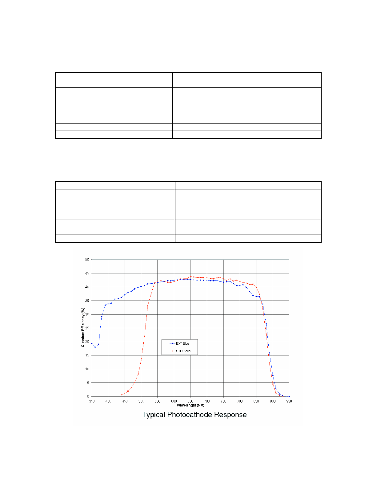
Figure 4.3-1: Spectral curve for Intensicam ................................................................................................................14
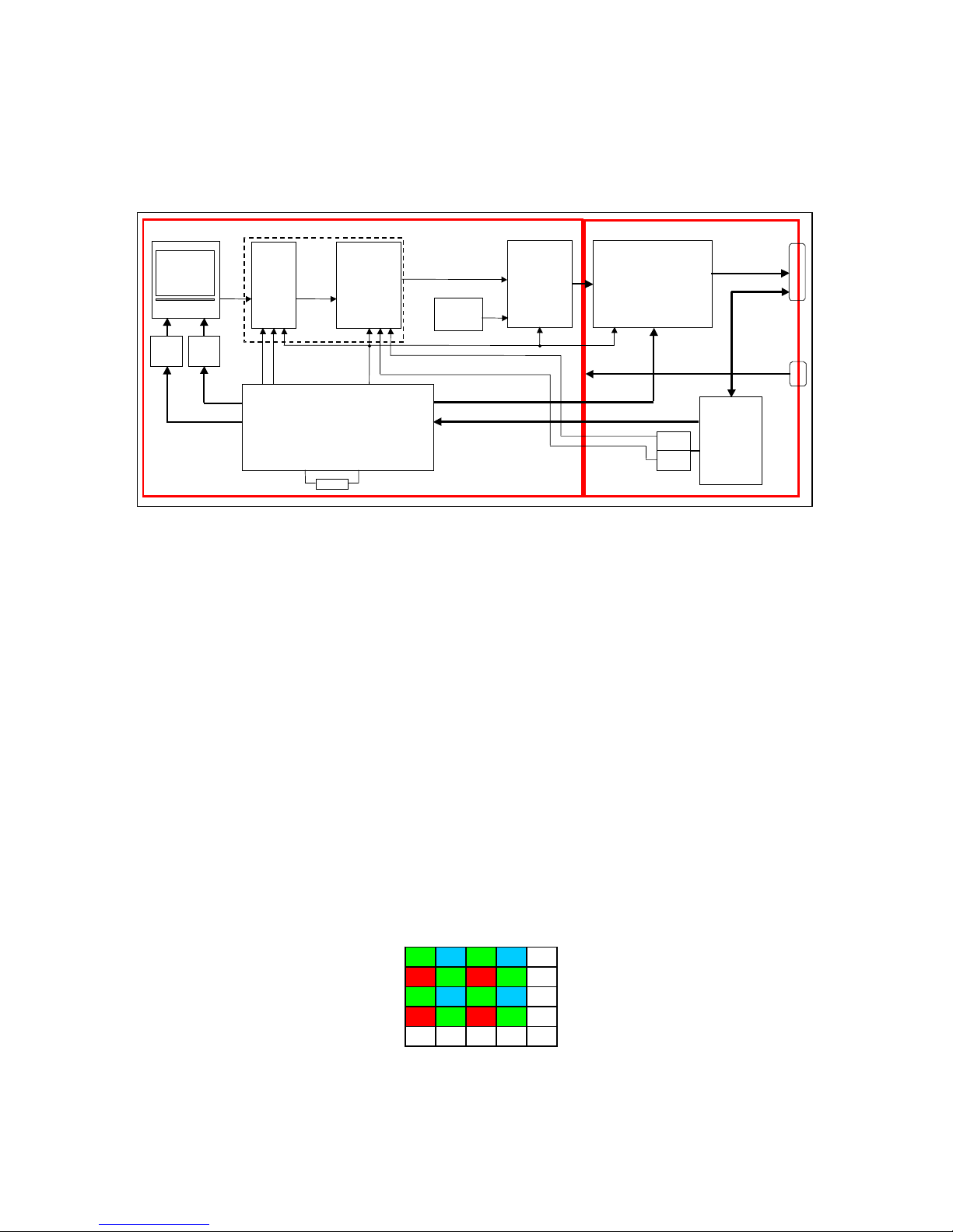
Figure 5.1-1: DVC-1412 camera block diagram (LVDS version shown) ...................................................................17
Figure 5.2-1: Bayer pattern color filter array...............................................................................................................17
Figure 7.1-1: Timing diagram--normal mode..............................................................................................................20
Figure 7.2-1: Timing diagram--shutter mode (HNL & HDL) .....................................................................................21
Figure 7.2-2: Asynchronous Reset ..............................................................................................................................22
Figure 7.2-3: Timing diagram—HDO Mode...............................................................................................................24
Figure 7.2-4: HDL mode .............................................................................................................................................25
Figure 7.3-1: Timing diagram--long exposure.............................................................................................................26
Figure 7.5-1: Asynchronous Reset ..............................................................................................................................27
Figure 7.5-2: Pulse driven integration mode, showing long/short exposure with minimum latency...........................28
Figure 7.6-1: Bin 2x2 case...........................................................................................................................................30
Figure 7.9-1: Intensicam spectral response..................................................................................................................36
Figure 7.10-1: Cooled (left) and non-cooled (right) multi-spectral cameras. ..............................................................38
Figure 7.10-2: Color filter wheel module ....................................................................................................................40
Figure 8.1-1: Bayer Pattern CFA.................................................................................................................................49
Figure 9.5-1: Luminous Gain versus IGN Argument ..................................................................................................57
Figure 11.1-1: 1412 with LVDS connector .................................................................................................................62
Figure 11.1-2: 1412 with CameraLink connector........................................................................................................63
Figure 11.1-3: 1412 Camera with 1394 Connector .....................................................................................................64
Figure 11.1-4: 1412 TE Cooler Camera (LVDS model shown)..................................................................................65
Figure 11.1-5: Intensicam-1412 Image Intensifier Camera (LVDS shown)................................................................66
Figure 11.1-6: 1412-Multispectral Wheel Non-Cooled Camera (LVDS shown) ........................................................67
Figure 11.1-7: 1412-Multispectral Wheel Cooled Camera (FireWire shown) ............................................................68
Figure 11.2-1: DVC-1412-to-pixeLNYX cable...........................................................................................................69
Figure 11.2-2: CameraLink cable................................................................................................................................70
Figure 11.2-3: DVC-1412-MV1500 cable...................................................................................................................71
Figure 11.2-4: DVC-1412-to-Matrox Meteor II DIG cable (LVDS)...........................................................................72
Figure 11.3-1: Camera rear view showing connector pin numbers (LVDS connections shown)................................73
v
Page 6

LIST OF TABLES
Table 7.6-1: Binning commands..................................................................................................................................29
Table 7.7-1: Slow-scan mode commands....................................................................................................................34
Table 9.4-1: Gain Table...............................................................................................................................................53
Table 9.4-2: Offset Table.............................................................................................................................................53
Table 11.3-1: Camera connector information..............................................................................................................75
Table 11.3-2: Power supply connector pinout .............................................................................................................75
Table 11.3-3: Digital video connector pinout..............................................................................................................76
vi
Page 7

1 INTRODUCTION
DVC Company, based in Austin, Texas, is a manufacturer of cost-effective, high performance digital video
cameras. We thank you for purchasing from the DVC-1412 product series.
This series of cameras is based on the premise that precise image processing applications demand megapixel cameras that are optimized for the performance available from today’s leading-edge CCDs, while
maintaining an acceptable price to performance ratio.
The 2/3” interline Sony ICX285 CCD imager used in the DVC-1412 cameras has a 1392(H) x 1040(V)
progressively-scanned image format and has a pixel size of 6.45µm x 6.45µm. The CCD sensor has a
particularly high QE in the blue-green region of the spectrum resulting in higher sensitivity for most
applications.
The DVC-1412 series of cameras includes non-cooled, cooled, intensified, and multi-spectral versions.
Furthermore, a choice of I/O options is available: LVDS, CameraLink, or FireWire. Standard camera
features include high-speed shuttering, long-term integration, pulse driven integration, and gain/offset
control. All DVC cameras come with a standard 2-year warranty and use industry-standard “C-mount”
lenses.
This camera series also includes Intensicam II, which utilizes a gated, Gen III image intensifier, fiberoptically coupled to the CCD.
With the LVDS version, the 10 frames/s video data is provided in a 12 bit parallel, differential LVDS
format, which is "plug-and-play" compatible with industry-standard image processors. The digital data,
pixel clock, enable line, and enable frame signals are accessible via the DB-44 connector.
The CameraLink version transmits 10 frames/s, 12-bit data over an industry standard MDR-26 interface to
any CameraLink compatible frame grabber.
In the FireWire version of the camera, the LVDS output is replaced by an industry standard 1394A
interface. The camera provides 12-bit data at 10 frames/s when used with any OHCI-compliant FireWire
interface card.
Computer-based control of gain offset is provided to "tune" the dynamic range of the camera to the
application. This provides an optimum match between the dynamic range and sensitivity of the camera and
the requirements of the application.
The CCD is physically mounted in the cavity of a high-precision opto-mechanical plate for excellent
mechanical stability. vibration applications. An adjustable C-mount coupling allows critical system
focusing adjustments. In-camera digitization using the stable CCD pixel clock eliminates pixel jitter,
improves repeatability, and enables sub-pixel accuracy in image processing applications.
DVCView, a Windows GUI software package is supplied with the camera, allowing image viewing and
control of all camera operations. Five user programmable, single-click software “buttons” allow the user
to customize the camera to the imaging application.
This manual applies to all of the DVC-1412 cameras.
1
Page 8
2 INITIAL INSPECTION
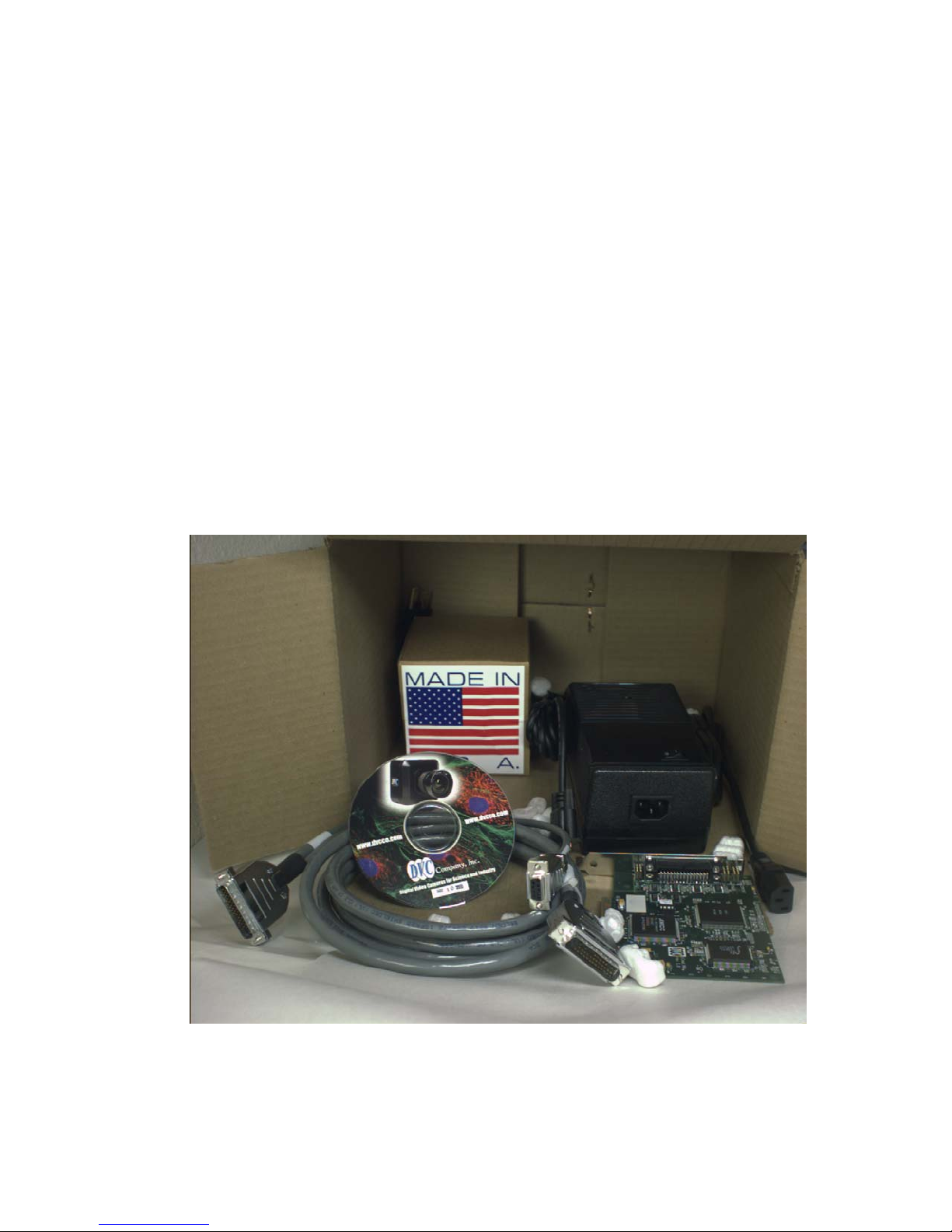
2.1 UNPACKING AND RECEIVING
These items were thoroughly tested and carefully packed in the factory. Upon acceptance by the
carrier, they assume responsibility for its safe arrival. Should you receive your DVC shipment in a
damaged condition, apparent or concealed, a claim for damage must be made to the carrier. To
return the product to the factory for service, please contact the DVC Customer Service Department
at (512)-301-9564 for a Return Material Authorization (RMA) Number. Returns are not accepted
without an RMA number.
If visual inspection shows damage upon receipt of this shipment, it must be noted on the freight bill
or express receipt, and the notation signed by the carrier's agent. Failure to do this can result in the
carrier refusing to honor the claim.
When the damage is not apparent until the unit is unpacked, a claim for concealed damage must be
made to the carrier immediately. Keep all cartons and packing materials. Since shipping damage is
the carrier's responsibility, the carrier will instruct you on filing the concealed-damage claim.
2
Page 9
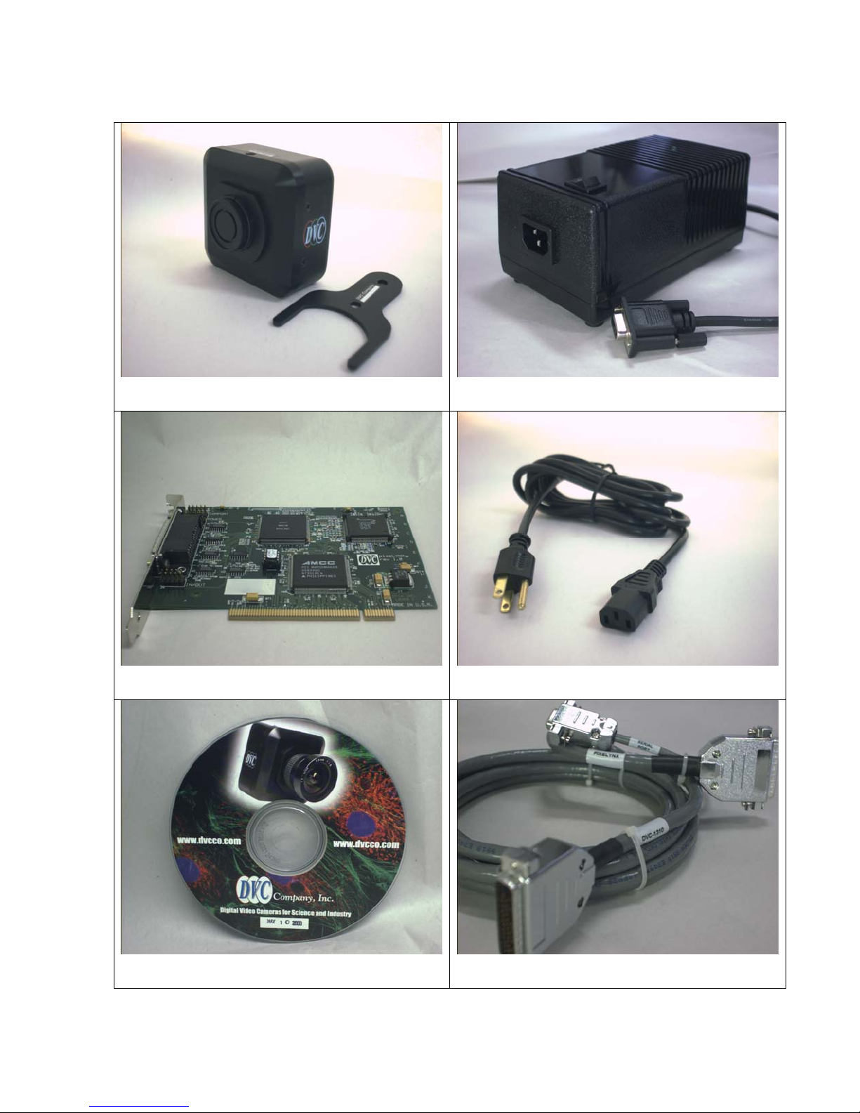
2.2 EQUIPMENT SUPPLIED (LVDS system)
Figure 2.2-1: DVC-1412 Camera and adjustment wrench
Figure 2.2-3: PixeLYNX board
Figure 2.2-2: Linear regulated power supply
Figure 2.2-4:US version of line cord with IEC320 receptacle
Figure 2.2-5: DVC CD-ROM
Figure 2.2-6: 10ft. interface cable, with 18” RS232 pigtail
3
Page 10
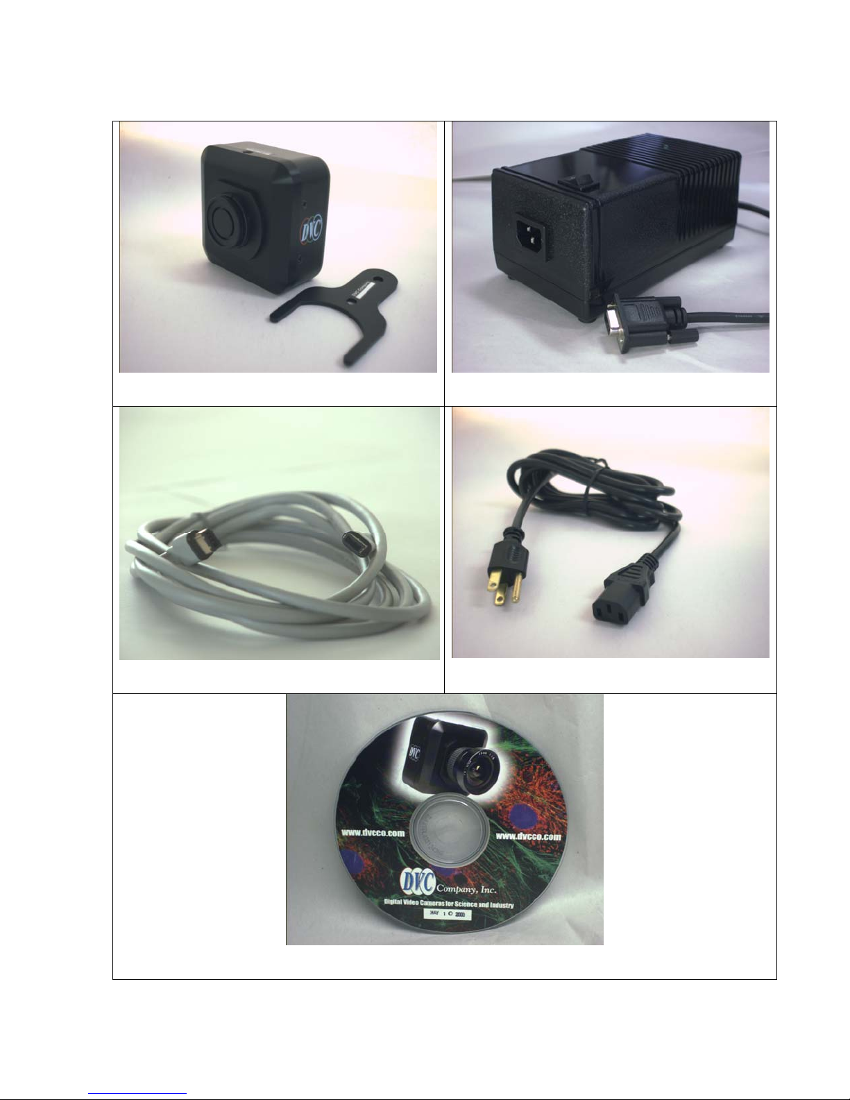
2.3 EQUIPMENT SUPPLIED (FireWire system)
Figure 2.3-1: DVC-1412 Camera and adjustment wrench
Figure 2.3-3: FireWire cable (actual color may vary)
Figure 2.3-2: Linear regulated power supply
Figure 2.3-4:US version of line cord with IEC320 receptacle
Figure 2.33-2.3-5: DVC CD-ROM
4
Page 11
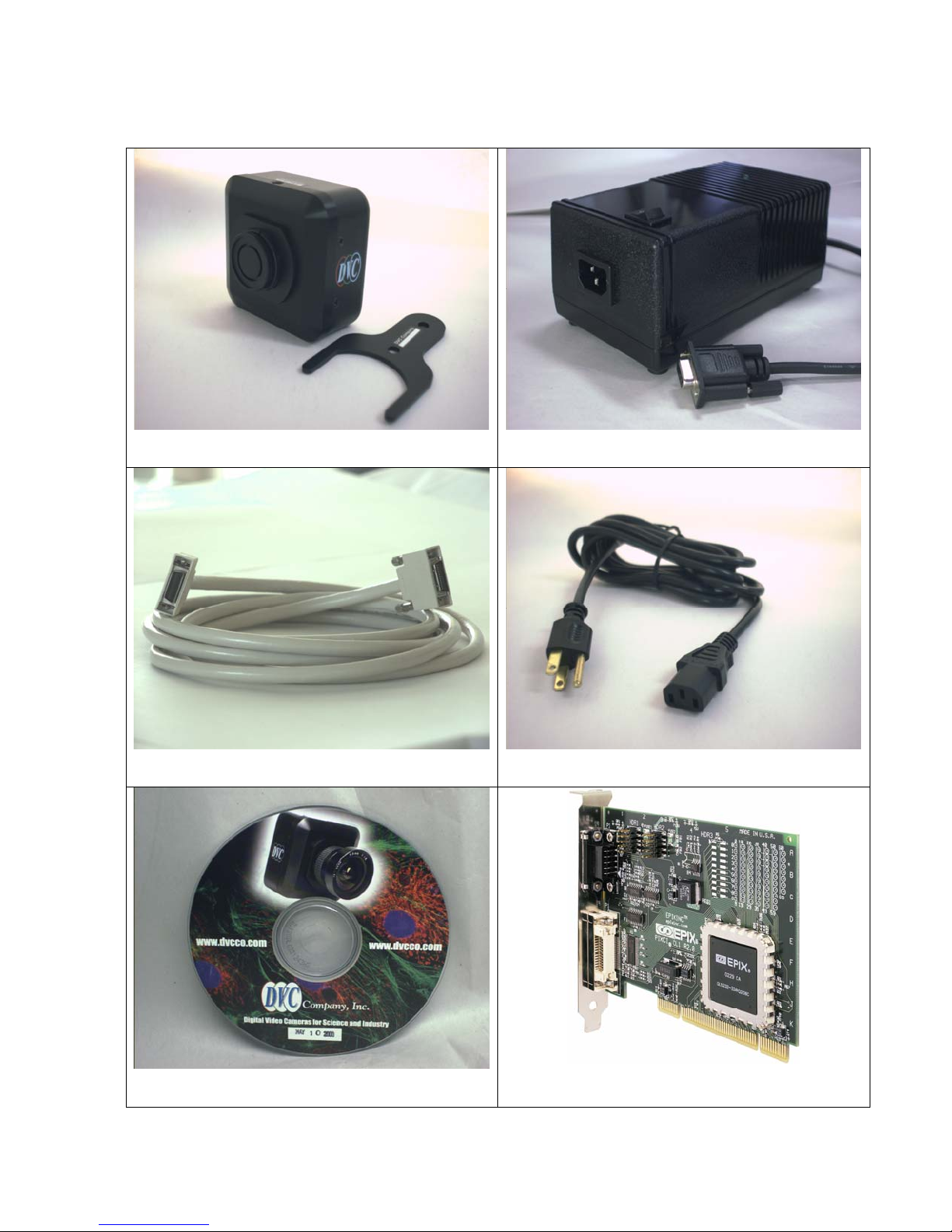
2.4 EQUIPMENT SUPPLIED (CameraLink system)
Figure 2.4-1: DVC-1412 Camera and adjustment wrench
Figure 2.4-3: CameraLink cable (actual color may vary)
Figure 2.4-2: Linear regulated power supply
Figure 2.4-4:US version of line cord with IEC320 receptacle
Figure 2.4-5: DVC CD-ROM
Figure 2.4-6: CameraLink board
5
Page 12
2.5 OPTIONAL ITEMS
The following items are optional items and may be ordered from authorized dealers of DVC. They
are not typically supplied with each Camera.
1. Lenses and/or other optical elements
2. Third party image analysis software, e.g. ImagePro, Adobe Photoshop®, QED Imaging,
Improvision, etc.
2.6 CAMERA POWER SUPPLY
DVC provides a power supply for use with the DVC-1412 camera. The electrical and optical
specifications of the camera are guaranteed only when used with DVC supplied accessories.
NOTE: The power is sealed for the safety of the operator. There are no user-serviceable parts
inside the power supply, and it should not be opened since there are dangerously high voltages
within. The warranty will be voided if the power supply is tampered with or opened.
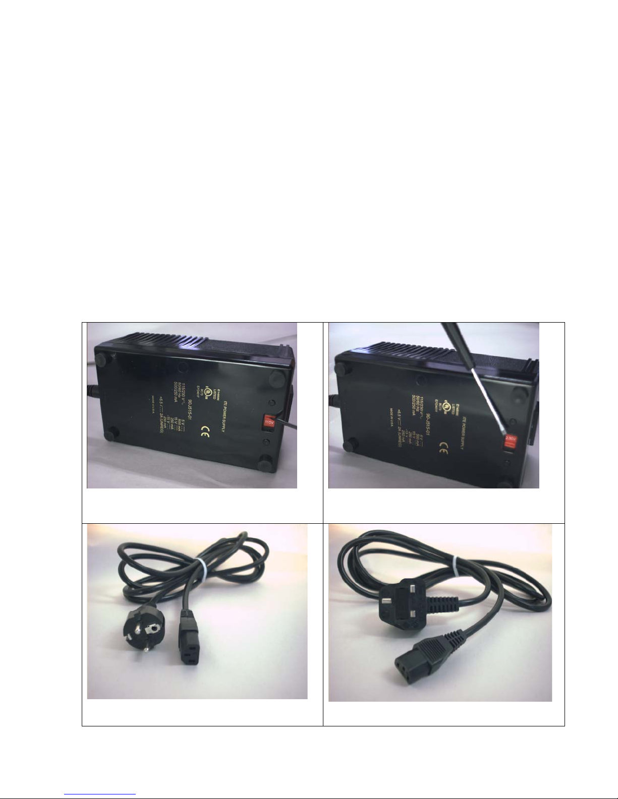
2.6.1 INTERNATIONAL APPLICATIONS
Figure 2.6-1: Bottom view of power supply showing voltage
selection switch (115V)
Figure 2.6-3: IEC line cord with Euro-style plug
6
Figure 2.6-2: Bottom view of power supply showing voltage
selection switch (220V)
Figure 2.6-4: IEC line cord with UK-style plug
Page 13

3 MAINTENANCE
3.1 IMPORTANT WARRANTY INFORMATION
There are no user-serviceable parts inside the camera. Removing the rear cover of
the camera without express authorization from DVC Company may void the camera
warranty.
This camera contains sensitive devices that can be damaged by static discharge. Use appropriate
static control methods when handling the camera. Avoid contact with connector pins when cables
and plugs are removed.
Depending on the model, your DVC camera may contain a glass, infra-red blocking filter to
prevent infra-red light from reaching the CCD sensor. This filter is integral to the lens mounting
ring and it also protects the CCD sensor faceplate or other optical components from contamination
and direct contact.
DVC cameras are manufactured in a clean environment, and each camera is thoroughly tested prior
to shipping to ensure that it meets our stringent specifications for cleanliness and quality. However,
accumulation of dust on the camera optical surfaces in the customer application are not covered by
warranty.
To ensure optimum image quality with any DVC camera, do not remove the protective lens-mount
cap until ready to mount the camera on the application. If the camera is removed from the
application, immediately replace the cap. Doing so will keep dust and other contaminants from
accumulating on the optical surfaces. In addition, please note the following model-specific
guidelines.
3.1.1 Intensified Cameras
The image intensifier is a delicate electronic device and can be permanently impaired by exposure
to excessive light. Damage to the intensifier due to overexposure is not covered under warranty.
Never run an intensified camera if it is not attached to an optical system, and always check
illumination levels carefully before activating the intensifier and increasing the intensifier gain.
Finally, follow cleaning guidelines outlined in section 3.2.3
3.1.2 TE-Cooled Cameras
The DVC Thermoelectrically-cooled cameras contain the CCD in a sealed, gas-filled chamber
having an anti-reflective glass window. Do not, under any circumstances, loosen or remove the
inner glass window from a cooled camera. Doing so will void the warranty. If it is suspected that
the seal has been broken or if the window breaks, do not apply power to the camera. Moisture may
have been introduced, and cooling in the presence of moisture will cause condensation and frost on
the CCD. Call DVC Customer Service. Otherwise, follow the cleaning guidelines in section 3.2.2
3.1.3 MultiSpectral Cameras
Unless specified otherwise, DVC multispectral cameras do not utilize a separate infrared filter.
When the lens is removed, it is possible to contact the filter surfaces and the filter wheel assembly.
Use precaution when changing filters and follow the installation and cleaning procedure in section
7.10.3.4.
Because the filter wheel takes up a portion of the fixed distance between the C-Mount mounting
surface and the image plane, care should be taken to ensure that the rear element of any lens to be
7
Page 14

used does not protrude into the filter cavity, which may cause damage to the lens, filter, or filter
wheel. See section 7.10 in this manual for more details.
3.1.4 Standard Cameras
While the lens mounting ring and locking flange allow the user some lens back-focus adjustment,
complete removal of the ring will expose the CCD faceplate and will likely cause debris to
accumulate on its surface. Extreme care should be taken to avoid completely removing the lens
mounting ring and exposing the CCD faceplate unless absolutely necessary. Fingerprints or
other evidence of contact with the CCD faceplate may void the warranty.
3.2 Cleaning Guidelines
Frequent lens changes, especially without careful attention to contaminants, can allow debris to
accumulate on the infra-red blocking filter and lens surfaces. Therefore, DVC Company provides
the following guidelines for cleaning those components.
3.2.1 Cleaning the lens or optical assembly
Please follow the manufacturer’s recommendations for cleaning. DVC Company is not responsible
for any damage caused to the lens or optical assembly caused by customer cleaning or misuse.
3.2.2 Cleaning the infra-red filter (Standard and TE-Cooled Cameras)
The infra-red filter is visible when the lens is removed, mounted inside the lens mounting
ring.
3.2.2.1 What must I do before cleaning the infra-red filter?
Do not remove the filter from the camera.
First, remove the lens and carefully examine the filter in a clean location under a
strong, direct light. Try to determine if the contaminants are a few dust particles,
oily smudge (such as fingerprints) or both.
3.2.2.2 What if the contamination is only a few dust particles?
Use a CLEAN, DRY (preferably brand-new), camel hair lens cleaning brush (such
as those used by photographers) to gently wipe the particles off of the filter.
3.2.2.3 What if the contamination includes a smudge?
The filter is a high-quality, coated optical component and should be treated with
extreme care. Scratches, chemical contamination, or other damage due to
improper cleaning may void the warranty.
• Remove the camera from the optical assembly and bring the camera to a
clean, dry location where it is safe to use flammable solvents (please see
caution below)
• Carefully loosen the lens mount lock ring using the supplied DVC lock
ring wrench.
• Orient the camera so that the lens mount is pointing downward and
carefully unscrew the lens mounting ring and integral filter.
• Place the camera face down on a clean, dry surface to prevent particles
from accumulating on the CCD faceplate.
8
Page 15

• Once the filter is removed, Use a CLEAN, DRY (preferably brand-new),
camel hair lens cleaning brush (such as those used by photographers) to
gently wipe the particles off of the filter.
• Re-examine the filter after removing the dust. If a smudge is still visible,
proceed by dipping a clean, lint-free cotton swab in ethyl or isopropyl
alcohol. The swab should be saturated, but not dripping.
• Carefully draw the swab once across the surface, then rotate the swab 180
degrees to expose the fresh surface and draw it across the filter surface
again. Be careful not to pool alcohol on the glass surface.
• Re-examine once again and repeat the process once, if necessary.
.
Caution: ethyl and isopropyl alcohols are highly flammable! Do not use near
extreme heat, arcing electrical equipment (such as space heaters) or open
flame! Use only with proper ventilation. Follow all safety instructions
provided by the manufacturer of the alcohol product.
If contamination continues to be a problem, please call DVC Customer Service for
assistance.
3.2.3 Cleaning the intensifier front element (intensified cameras)
The intensifier front element is the glass plate visible when the lens is removed. As
always, dust accumulation can be reduced by minimizing removal of the camera
from the application and replacing the protective lens cap during those periods the
camera is removed.
3.2.3.1 What must I do before cleaning the intensifier front element?
First, remove the lens and carefully examine the front element in a clean location
under mild direct light (care must be taken not to expose the intensifier to strong
light). Try to determine if the contaminants are a few dust particles, oily smudge
(such as fingerprints) or both.
3.2.3.2 What if the contamination is only a few dust particles?
Use a CLEAN, DRY (preferably brand-new), camel hair lens cleaning brush (such
as those used by photographers) to gently wipe the particles off of the surface.
3.2.3.3 What if the contamination includes a smudge?
DVC strongly recommends returning the camera to the factory for professional
cleaning to avoid damage to the camera. Scratches, chemical contamination, or
other damage due to improper cleaning may void the camera warranty.
If contamination continues to be a problem, please call DVC Customer Service for
assistance.
3.2.4 Cleaning the Multispectral Camera optical components (Multispectral Cameras only)
Follow instructions for removal of filters in section 7.10 and clean filters
individually using the instructions for cleaning the infra-red filter in section 3.2.2
above
9
Page 16
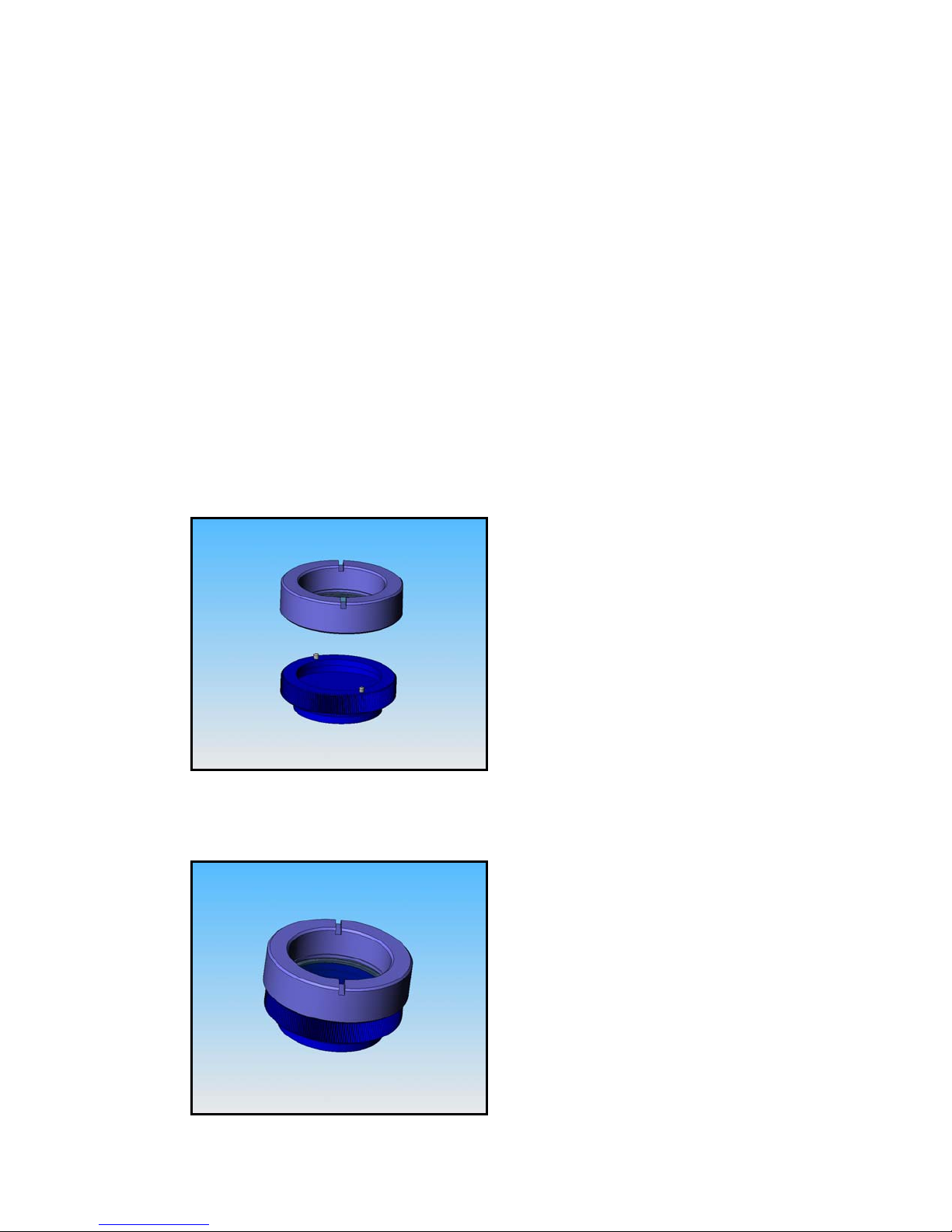
3.3 Infra-red filter removal and installation
The DVC1412A series cameras have very high quantum efficiency in the red and nearinfra-red regions of the spectrum, making them suitable for near-infra-red imaging
applications. In such applications, it may be necessary to remove the infra-red filter. It is
important to note that removal of the IR filter may allow debris to collect on the CCD
faceplate. Please use every precaution to avoid contact with the CCD faceplate and to keep
the camera securely mounted to the optical system or capped when not in use.
3.3.1 How to remove the IR filter
Caution: This procedure will cause the focus calibration to be lost. Readjustment of the lens back
focus will be required after reassembly
1. Loosen the lens mount lock ring with the wrench supplied by DVC
2. Unscrew the lens mount/filter assembly ring from the camera body and remove the lock ring
from the lens mount ring
3. Hold the lens cap with the pins sticking upward in one hand
4. Lower the lens filter assembly on to the pins with the other hand
10
Page 17
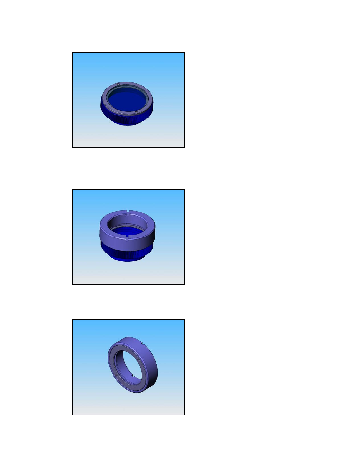
5. Hold the lens cap and rotate the lens ring anti-clockwise and then remove the lens ring.
6. Remove the filter from the filter ring with lens tissue and store in a protective container
7. Replace the lens ring on to the filter ring and screw on clockwise
8. Remove the lens ring from the lens cap
11
Page 18

9. Screw the lock ring back onto the lens mount ring and screw both back onto the camera. Adjust
focus by loosening the lock ring and rotating the lens mount ring to adjust the lens-to-CCD distance.
To re-install the IR filter or other filters, reverse the above procedure.
12
Page 19
4 CAMERA SPECIFICATIONS
4.1 OPTICAL
Sensitivity @ 1890°K
(measured without IR filter)
Pixel size and format
Monochrome: 0.022fc for full-scale, 0dB gain,
1/10 sec exposure.
6.45µm(H)X 6.45µm(V); interline format
Spectral Response See Figures 4.1-1, 4.1-2,
Figure 4.1-1: Monochrome camera spectral response
100
90
80
70
60
50
40
% Transmission
30
20
10
0
350 400 450 500 550 600 650 700 750 800 850 900 950
Wavelength (nm)
Figure 4.1-2: IR Filter Characteristics
13
Page 20
4.2 DIGITAL VIDEO OUTPUT
4.2.1 12 Bit RS-422/RS-644 (LVDS / FireWire)
Readout Rate 18 MHz, 9 MHz,
(user selectable via software)
Resolution/Frame Rate
(Binning: Monochrome model only)
Signal to noise >65 dB, at min. gain
Gamma 1.0 (linear)
1392 x 1040 at 10.2 f/s (1 x 1)
1392 x 520 at 20 f/s (1 x 2)
696 x 520 at 20 f/s (2 x 2)
348 x 260 at 39 f/s (4 x 4)
174 x 130 at 68 f/s (8 x8)
4.3 1412 INTENSICAM
(The data shown below represents the “standard” photocathode response. Extended blue
and special Gen IV versions are also available).
QE > 35% Quantum Efficiency from 500 to 800 nm
Sensitivity 1X10⁻⁸ fc Sensitivity (faceplate) @ 2854K, 10fps
Photocathode GaAs photocathode, std spectral response 450 to
900 nm
Intensifier life > 10,000 hrs @ 10-5 fc or lower
Geometric Distortion < 1%
Resolution 64 1p/mm
Gating 50 ns to 98 ms
Figure 4.3-1: Spectral curve for Intensicam
14
Page 21

4.4 CAMERA CONTROL
RS-232C, C-View Interface Software module, standard
Gain control 30 dB
Offset control (black) 0% to 6 % in 16 steps
High speed shutter
Long Exposure control 98 ms to 15 min in two ranges
93 µs to 98 ms
4.5 ELECTRICAL
Timing Progressive scan
Power Supply Voltages &
Current requirements
Clock Rate 18 MHz derived from internal crystal oscillator
± 15 V DC each @ 250 mA
+ 5 V DC @ 250 mA
4.6 MECHANICAL: STANDARD LVDS/FIREWIRE/CAMERALINK
CAMERAS
Weight (without lens) 12 ozs. (340 grams)
Temperature limits (operating)
Temperature limits (storage)
Dimensions 3.25” (H) X 3.25” (W) X 1.73” (L)
Lens mount Industry-standard C- mount
Camera mount 2 X ¼ - 20 threaded holes for top/bottom mount
Digital Video Connector
Power Supply Connector
-10°C to 50°C
-30°C to 70°C
LVDS: DB-44, female connector
(See Appendix C)
FireWire: Standard 1394A connector
CameraLink: Standard MDR-26, 26-pin connector
LVDS: DB-9, Male connector (see Appendix C)
Firewire: Standard 1394A connector
4.7 MECHANICAL : COOLED CAMERAS
Weight (without lens) 27.9 ounces (792 grams)
Temperature limits (operating) -10°C to 50°C
Temperature limits (storage) -30°C to 70°C
Dimensions 3.90" (H) X 3.90" (W) X 2.80" (L)
Lens mount Industry Standard C-Mount
Camera mount 4 X ¼ - 20 threaded holes for top/bottom mount
Digital Video Connector
Power Supply Connector
4.8 MECHANICAL : INTENSICAM
Weight (without lens) 22.0 ounces (624 grams)
Temperature limits (operating) -10°C to 50°C
Temperature limits (storage) -30°C to 70°C
LVDS:DB-44, female connector (See Appendix C)
Firewire: Standard 1394A connector
CameraLink: Standard 26-pin connector
LVDS: DB-9, Male connector (see Appendix C)
Firewire: Standard 1394A connector
15
Page 22

Dimensions 3.25” (H) X 3.25” (W) X 3.20” (L)
Lens mount Industry Standard C-Mount
Camera mount 2 X ¼ - 20 threaded holes for top/bottom mount
Digital Video Connector DB-44, female connector (See Appendix C)
Power Supply Connector DB-9, Male connector (see Appendix C)
NOTE: See Appendix A for dimensioned mechanical diagrams.
16
Page 23
5 CAMERA FUNCTIONAL DESCRIPTION
5.1 BLOCK DIAGRAM
Gain
DAC
Offset
DAC
I/O board
Imaging
Area
(1300 x 1030)
CCD Sensor
Vertical
Drivers
Vertical
Horiz.
Driver
CCD
Video
Horizontal
CDS
(Correlated
Double
Sampling)
S/H CCD
Video
S/H signals
Timing logi c:
Clock generation
Generation of all CCD control signals
Generation of all handshaking signals
Exposure control
Crystal
CCD and Video Board
Video amplif ier:
Gain control
Offset control
Clamping
A/D reference
generation
Timing signals
Processed CCD Video
A/D
references
Gain control
voltage (0 to 3V)
Offset control
voltage (0 to 3V)
Handshaking signals
Mode/Exposure control
A/D Converter
Analog/Digital
conversion
TTL to LVDS driv ers:
single ended TTL to parall el,
differenti al LVDS output
DB9-M Connector
Microprocessor:
RS232 interface
Mode logic
Gain/offset control
DB-44 F
connector
(Digital
Video)
RS232
signals
(Pwr Supply)
+15V,-15V,+5V
Camera
Figure 5.1-1: DVC-1412 camera block diagram (LVDS version shown)
5.2 CCD AND VIDEO BOARD
5.2.1 CCD Sensor
Light from the scene is brought into focus at the imaging plane of the CCD. A 1mm thick infrared
blocking optical removable filter blocks out the IR component of the light. The IR blocking filter is
attached to the c-mount adapter ring. For non IR multi-spectral imaging applications with the
DVC-1412 AC Mount Adapter without an IR filter is available.
The following functions take place within the CCD:
5.2.1.1 Integration
During the integration period, photon-induced charge is integrated in the active charge site wells.
The amount of charge that is integrated in each active charge site well is proportional to the
illumination received at each active charge site on the CCD. In the case of the color camera, each
charge site has a Red, Green or Blue color filter over the field, designating it as a Red, Green or
Blue pixel. The filter pattern that is used is referred to as a Bayer pattern, which is shown below:
GBGB ..
RGRG..
GBGB ..
RGRG..
::::::
Figure 5.2-1: Bayer pattern color filter array
17
Page 24
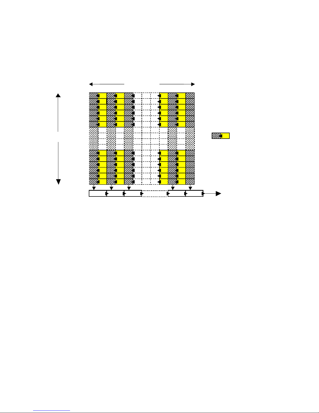
5.2.1.2 Charge Transfer
During the Vertical blanking interval, the charge that was integrated in each active charge site
during the previous exposure (normally 1/10 sec, or one frame) is shifted to an adjacent opaque
storage charge site. In the figure below, active charge sites are designated by the letter “I” for
integration and the opaque storage charge sites are designated by the letter “S” for storage.
1392 columns
S I S I S I S I S
S
I S I S I S I S
S
I S I S I S I S
S
I S I S I S I S
S
I S I S I S I S
S
I S I S I S I S
S I
1040 rows
S I S I S I S I S
S
I S I S I S I S
S
I S I S I S I S
S
I S I S I S I S
S
I S I S I S I S
S
I S I S I S I S
H-line transfer
Horizontal shift register
Charge transfer
(once per frame)
Charge detection node
Figure 5.2-2: Block diagram of CCD
5.2.1.3 Readout
In the following adjacent frame, the charges are transferred vertically, one line at a time, from the
storage charge sites of the CCD to an on-chip horizontal shift register and then sequentially to the
detection node where they are made available as signal voltages. NOTE: While one frame is being
read out from the opaque pixels, the next frame is being integrated in the active charge sites of the
CCD.
5.2.2 Video Processing
The low-level video signal voltage from the CCD is clamped (for black reference) and fed through
a high-speed CDS correlated double sampling CDS amplifier. The CDS process is required to
remove a significant source of noise from the video signal. The video signal is then amplified in the
next stage, which has voltage-controlled-gain and voltage-controlled-offset. The control voltages
for gain and offset are 0 to 3V in range and are derived via on-board digital-to-analog converters
(DACs) which are controlled via the host PC interface.
5.2.3 Video Digitization
The video signal output from the video processor is fed to a 12-bit Analog-to-Digital converter.
The 12 bit digital data is available at a connector on the board.
18
Page 25

5.2.4 Voltage Regulation
Input voltages (+15V, -15V and +5V) are converted into several positive and negative voltages
required by the CCD and in the video processing circuits.
5.2.5 Timing
This logic block on the CCD and Video board performs the following functions:
• Generation of CCD timing signals
• Generation of Video & handshaking timing signals
• Asynchronous Reset function
• Mode control function
• Exposure control function
5.3 DIGITAL I/O BOARD
5.3.1 LVDS Version: TTL to LVDS Drivers
The Digital Video Data is latched and converted to an LVDS format (on the I/O board) for
transmission as a balanced, differential signal along the cable which consists of shielded twisted
pairs.
5.3.1.1 RS232 Interface
This is made up of a microprocessor-based circuit, which communicates via an on-board UART
with the serial port of a PC.
5.3.2 Fire Wire Version
5.3.2.1 Isochronous Data
The digital video data is latched and converted to an isochronous IEEE 1394 A (Fire Wire) format
for transmission as a serial data stream on a standard Fire Wire interface cable.
5.3.2.2 Asynchronous Data
Camera control commands from the host PC are sent via the Fire Wire interface cable in the form
of asynchronous data. The data is received and translated into internal camera control signals that
are used to set gain, offset exposure etc. in a variety of camera modes.
5.3.3 CameraLink Version
The Digital Video Data is latched and converted to an CameraLink format (on the CameraLink
board) for transmission as a balanced, differential signal along the cable which consists of shielded
twisted pairs. Command and control data (including asynchronous reset signals, under frame
grabber/software control) are also sent in accordance with the CameraLink specification.
NOTE: The command set for LVDS & CameraLink versions of the camera are identical.
19
Page 26
6 INSTALLATION
Refer to Installation and Operation Manual
7 MODES OF OPERATION
7.1 NORMAL MODE
In each mode description, the serial mode commands (CameraLink and LVDS versions only)
are shown. Please refer to the serial mode commands details in Section 9.4.
NRR: Normal mode with reset
NOR: Normal without reset
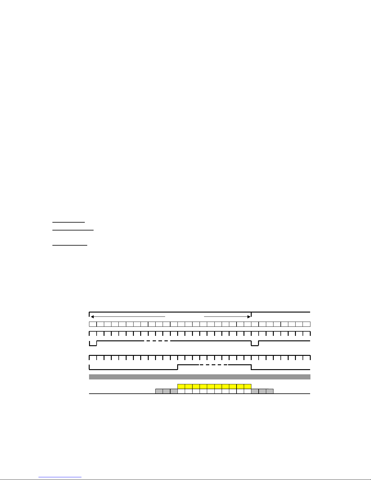
In the normal mode of operation, the following signals are used to synchronize a digital frame
grabber to the camera:
Pixel Clock
Enable Frame
frame and the falling edge signifies the end of a valid frame
Enable Line
and the falling edge signifies the end of a valid line.
The Horizontal and Vertical Drive signals are usually outputs generated by the camera.
In the timing diagram show below, charge transfer from the active (imaging) charge sites to
adjacent (opaque) storage sites takes place at the beginning of a frame. In this process, all the
charge that was accumulated in the imaging charge sites during the previous frame is transferred to
the opaque storage sites.
Charge transfer
Line count
Horizontal Drive
Vertical Drive
: Periodic 18 MHz, square wave output which is synchronous with digitized pixel data.
: Periodic 10 Hz (frame rate) output; the rising edge signifies the start of a valid
: Periodic 10.7 KHz (line rate) output; the rising edge signifies the start of a valid line
1 2 3 4 5 6 7 8 9 10 11 12 13 … … … 1047 1048 1049 1050 1051 1052 1 2 3 4 5 6 7 ....
Exposure = 1/10 sec
Enable Line
Enable Frame
Pixel Clock
CCD Output
BLK BLK BLK 1 2 .... .... .... .... … … … 1030 BLK BLK BLK
V I D E O
Figure 7.1-1: Timing diagram--normal mode
20
Page 27
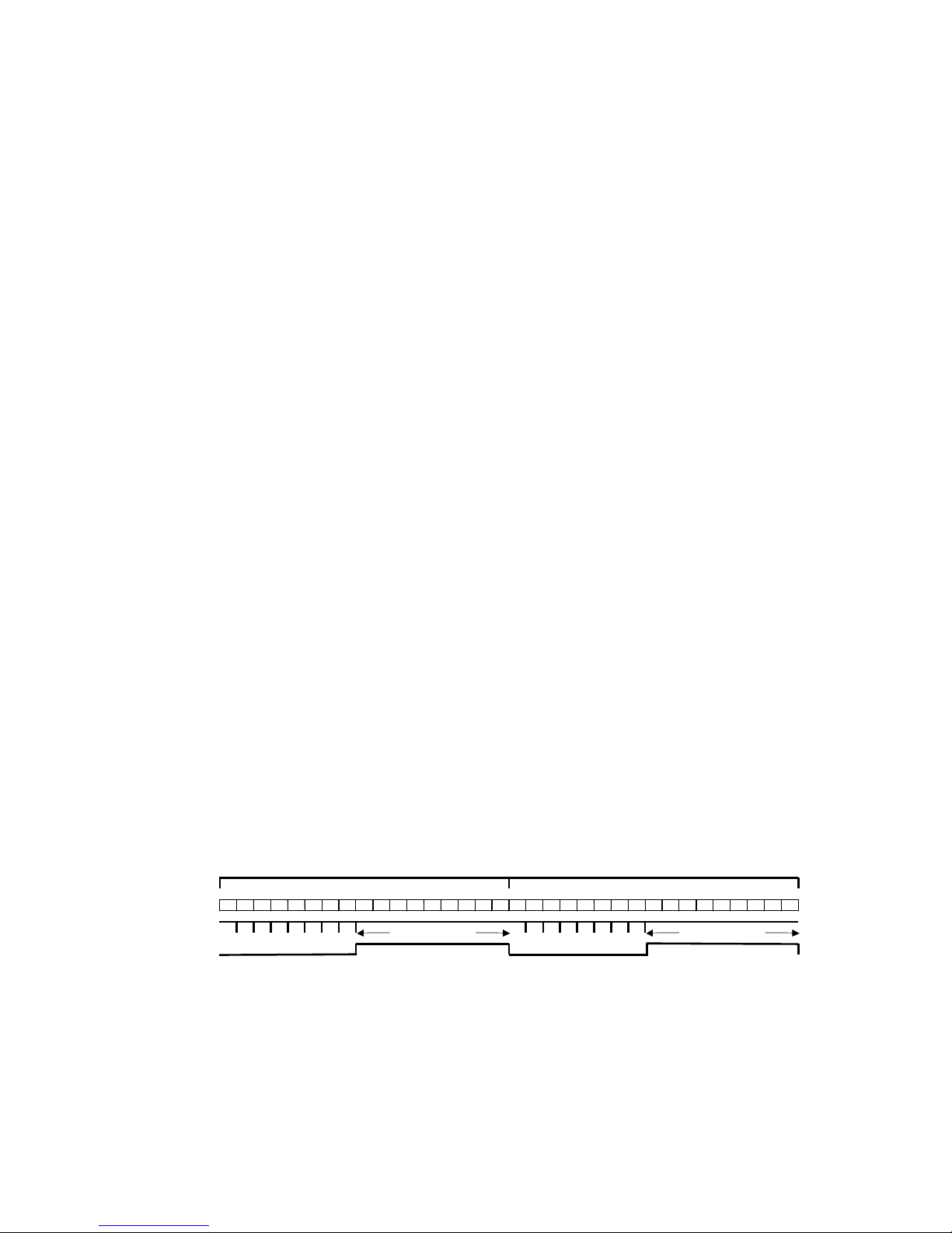
Every horizontal line during the next frame, one line of the charge matrix in the opaque storage
sites is shifted vertically into a horizontal shift register. The horizontal shift register is clocked out,
one pixel at a time, on to a charge detection node that converts it to a voltage, which can be
sampled and digitized.
7.2 HIGH SPEED SHUTTER
HDO: High speed shutter with discharge (one-shot)
HNL: High speed shutter without discharge
When one of the high-speed shutter modes is selected, the duration of exposure is set as an integral
number of horizontal-line-periods. In the shutter modes, the duration of exposure can be set from 1to-1045 horizontal lines, in 1-horizontal-line-period (approx. 90µ sec) increments.
7.2.1 Setting The Exposure Duration
The Camera exposure settings are set using the EXP command, e.g. EXP 0A5 sets the exposure to
0x0A6 number of lines in all the shutter modes (HDO, HDL, HNL). The duration of exposure in
the high-speed shutter modes is from 1 through 1052 horizontal line periods, represented by an 11bit control word.
High-speed shutter mode without discharge (HNL): In this mode asynchronous resets are ignored.
This mode is designed for use in applications in which the electronic shutter is used primarily as a
means of light level control, i.e. as an electronic "iris" in cases where there is too much light in the
field of view. This is usually done to prevent saturation of the CCD with a full frame or 1/10sec
exposure. The normal sequence of timing (see fig. 7.2-1) is followed and there are no interruptions
of the Enable_frame, Enable_line and Pixel Clock signals.
In the example below, exposure is set to 1/500sec; this translates to 21 horizontal-line-periods (21 x
93µ sec = 1/500sec). In order to achieve this exposure, the CCD must be exposed for 21 line
periods out of the total of 1045 line periods in the frame. Since the CCD has to continuously
integrate charge, the 21 line-period exposure is obtained by "dumping" the charge every line for the
first 1020 line periods, and then stopping the "dumping" action for the last 21 line-periods. At the
end of this “active” 21 line exposure period, the charges are transferred to the storage matrix
followed by readout. This is shown graphically in the timing diagram below.
Charge transfer
Line count
Charge dump
Strobe output
1 2 3 4 .... .... .... .... 1031 1032 1033 1034 .... .... 1050 1051 1052 1 2 3 4 .... .... .... .... 1031 1032 1033 1034 .... .... 1050 1051 1052
Figure 7.2-1: Timing diagram--shutter mode (HNL & HDL)
7.2.2 Strobe
In many applications, objects in the field of view can be moving too rapidly to be properly imaged
under normal conditions. A combination of the high-speed shutter and a strobe may be used to
stop motion. It is often desired to synchronize the strobe action with the camera exposure. For this
Exposure = 21 lines Exposure = 21 lines
21
Page 28
purpose, a STROBE output pulse is generated within the camera. The STROBE output pulse
allows an external strobe light to be turned on during the exposure period. Since the duration of the
exposure is a user-programmable setting, the start-time (relative to the vertical timing of the
camera) and the duration of the STROBE output pulse also vary, depending upon the shutter
setting.
The strobe output pulse is generated to coincide with the exposure period. It is asserted (rising
edge) after the last "charge dump" pulse in each frame. It goes low at the next CCD readout pulse
(see above diagram). The strobe light can be activated at any time during the HIGH duration of the
strobe output pulse.
7.2.3 Reset & Shutter
In some applications, it is necessary to synchronize the camera to an external event. In order to
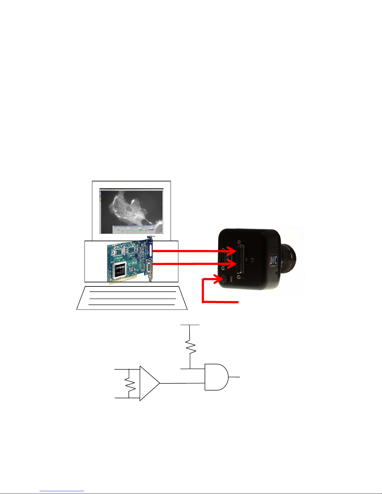
allow flexibility, two camera RESET methods are provided: TTL and differential.
CC1+ / INPUT 1 +
(LVDS differential input
from frame grabber board)
CC1- / INPUT 1 –
INPUT 1 +
INPUT 1 –
VRST_INT
(TTL)
VRST_INT (TTL)
+ 5V
CAMERA RESET
(INTERNAL SIGNAL)
Figure 7.2-2: Asynchronous Reset
22
Page 29

NOTE: Frame grabbers have the ability to control the differential input (CC1+, CC1-) or
(INPUT1+, INPUT1-) of the camera. This is facilitated by connecting them via two wires within
the camera-framegrabber interface cable to differential frame grabber outputs that are driven by a
General Purpose register bit that is to be controlled by host software. The TTL input (VRST_INT)
is usually NOT connected via the camera-framegrabber interface cable. Therefore, in most
applications, the VRST_INT signal floats HIGH,enabling resets from the framegrabber (under
control of the host software). In some cases, however, users may want to feed a TTL reset signal
directly to the camera, e.g. from an optical detector in an inspection application. In this case, the
user must ensure that the differential input (INPUT1 or CC1) is either driven HIGH or allowed to
float HIGH.
Within the camera, these two signals are logically AND-ed together and the resulting RESET
signal is used to reset the counters within the camera-timing chip. If either the TTL (VRST_INT
signal) or the differential (INPUT1 or CC1) is unused it floats HIGH due to internal pull-ups. The
other signal may be pulled "LOW" to cause a reset to the camera.
In cameras that have an auxiliary input connection, the VRST_INT (TTL) input is available as one
of the pins. In some applications, this input can be used to reset the camera directly instead of
generating resets from the frame grabber.
In the LVDS version, these inputs are called VRST_INT (TTL-pin39 of the DB44 connector) and
INPUT1(differential LVDS-pins [34,35] of the DB-44 connector). The default level for both these
signals is logic "HIGH".
In the CameraLink version, based on the CameraLink specifications, the CC1 signal allows the
CameraLink compliant PCI board to reset the camera under software control. In addition, a 6-pinmini-DIN auxiliary connector is provided, that includes a TTL reset input called VRST_INT.
23
Page 30
7.2.4 Reset Modes
In the HDO and HDL shutter modes, an asynchronous falling edge on the VRST_INT (TTL) or
CC1/INPUT1 (differential) input of the camera is used to synchronize the exposure period of the
camera to the outside world (the rising edge is not significant, however, the LOW duration should
last at least 1µsec). Since the falling edge is truly asynchronous, in most instances it would have
the effect of interrupting the readout of a previously exposed frame from the storage area elements
of the CCD; a residual charge from the previous exposure therefore may exist on the storage area
elements. This charge must be removed from the storage area by a “discharge” process before the
next charge transfer takes place.
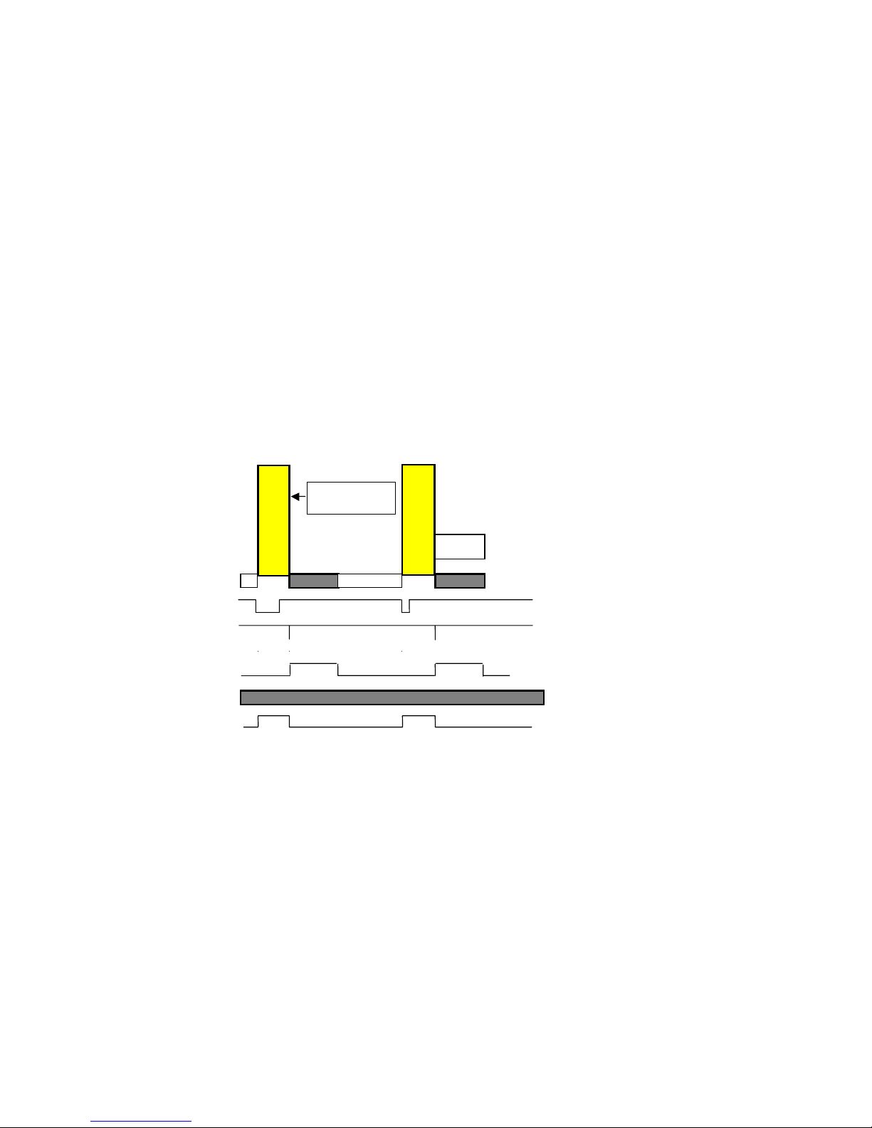
7.2.4.1 One Shot high speed shutter with discharge (HDO)
This mode is also referred to as the "one-shot" or "snapshot" mode. In this mode, the camera acts
like a snapshot digital camera. The camera outputs no frames (and no Enable_Frame signals) until
a reset signal is received (see above section related to reset signals). Once a reset signal is received,
the camera immediately performs one-and-only-one exposure (with the duration determined by the
previously set EXP command) resulting in one-and-only-one valid Enable_Frame signal. NOTE:
there is no latency or delay between the falling edge of reset and the start of the exposure.
E
X
P
O
S
U
R
E
User defined
exposure period
E
X
P
O
S
U
R
E
1 frame =
1/12sec
READOUT
NO VIDEO
1/10 s
Pixel Clock and Enable_Line (run continuously)
READOUT
VRST_INT (TTL) or INPUT1 (LVDS)
CHARGE TRANSFER (Internal Signal)
1/10 s
ENABLE_FRAME
STROBE OUT (TTL)
Figure 7.2-3: Timing diagram—HDO Mode
In a typical frame grabber based system, the displayed image is updated only when the reset is
generated; until then, the previously captured image (resulting from the previous reset) is
displayed. Therefore this mode is referred to as the asynchronous "snapshot" mode.
NOTE: The frame grabber should be capable of sustaining long periods of time without receiving
an Enable-Frame signal.
The exposure is set, as in all shutter modes, via the serial EXP command with its 11-bit argument.
For example, EXP 014 will set up the exposure to be equivalent to 21 lines of exposure (Hex"014"
= Decimal 20); since one-line-period is 93µsec, this is the same as 21 x 93µsec = 0.002sec or
1/500sec.
24
Page 31
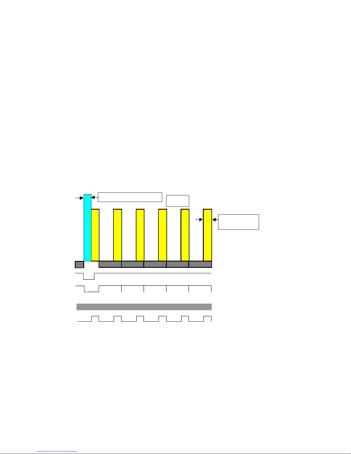
7.2.4.2 High speed shutter with discharge (HDL)
If an asynchronous reset occurs while the camera is in this mode, the residual charge in the storage
area from a previous exposure is flushed out (discharged) by a sequence of vertical channel transfer
pulses. This period lasts for 6.8msec (see timing diagram below). NOTE: the discharge pulses
affect only the storage area; the "charge dump" pulses that are required to clear the imaging area
are generated immediately after the discharge within the 6.8mSec period. This is followed by the
exposure period and then the readout of the integrated charge. As shown below in the timing
diagram, the normal sequence of the Enable_frame signal is interrupted by the asynchronous reset
input; It is forced LOW by the falling edge of the reset signal and remains low until the discharge
and exposure periods are completed (6.8mS + user_defined_shutter_exposure). The rising edge of
the Enable_frame signal signifies the start of the readout process of the synchronized frame.
NOTE: the Enable_line and Pixel Clock signals are un-interrupted by the reset signal and run
continuously.
NOTE: If the exposure period is greater than 80 lines, then a special condition exists, which
allows a concurrent discharge and exposure, eliminating the taking period between the falling edge
of reset and the start of exposure that exists in cases where the exposure period is less than 80 lines.
After the synchronized frame is readout, normal shutter operation resumes until the next falling
edge of the asynchronous reset is received.
Discharge duration = 6.8ms
D
i
s
E
c
X
h
P
O
a
S
r
U
g
R
e
E
E
X
P
O
S
U
R
E
READOUT
Pixel Clock and Enable_Line (run continuously)
READOUT
E
X
P
O
S
U
R
E
E
X
P
O
S
U
R
E
READOUT
1 frame =
1/10 sec
E
X
P
O
S
U
R
E
READOUT
E
X
P
O
S
U
R
E
READOUT
User defined
exposure period
VRST_INT (TTL) or INPUT1 (LVDS)
Enable_frame
STROBE OUT (TTL)
Figure 7.2-4: HDL mode
25
Page 32

7.3 N FRAME INTEGRATION
NFR: "N" frame integration (low speed shutter)
When the low-speed shutter mode (or N Frame Integration mode) is selected, the duration of
exposure is set as an integral number of frames. For the DVC-1412 camera, the duration of
exposure can be set from 1-to-1024 frames, in 1-frame increments. NOTE: since one frame is
1/10sec or 100msec, the range of control is from 1/10sec to 102 sec.
If the exposure is set to, for example, 1 second ; this translates to 10 second-periods (10 x 1/10sec =
1sec). In order to achieve this exposure, the CCD must be exposed for 10 frame periods between
transfers. Since EXP000 corresponds to a 1-frame exposure a 12 frame exposure will result from
an EXP 009, setting.
In order to maintain synchronization with a frame grabber, the pixel clock and enable line signals
are un-interrupted during exposure and subsequent readout. The enable frame signal, however, is
set "low" during exposure and goes "high" during readout to signify that the accumulated frame is
being read out and may be captured by the frame grabber. This is shown graphically in the timing
diagram below.
NOTE: The frame grabber should be capable of sustaining long periods of time without receiving
an Enable-Frame signal.
VRST_INT (T TL) or INOUT1 (RS-422)
Transfer Pulse (In ternal Signal)
Integrated
FRAME 1 FRAME 2 FRAME 3
INTEGRATION PERIOD = N * 1/10 sec INTEGRATION PERIOD = N * 1/10 sec
Video Blanked
ENABLE FRAME
FRM N-1 FRAME N READOUT
ENABLE LINE & PIXEL CLOCK (RUN CONT INUOUSLY)
Reset operation in the "N" Frame Integration Mode
Figure 7.3-1: Timing diagram--long exposure
Image
FRAME 1 FRAME 2 FRAME 3 FRM N-1 FRAME N READOUT
Video Blanked
Integrated
Image
7.3.1 Reset Operation in N-Frame Integration Mode
During the N-Frame integration mode, a falling edge of the VRST_INT (TTL) or the
INOUT1(LVDS) resets the camera and initiates a new N-frame exposure (as shown above).
7.4 ULT: ULTRA-LONG-TERM EXPOSURE
This mode is identical to the NFR mode, except that there is a x120 multiplier in the EXP
argument. This means that an EXP argument of N will have the effect of setting up an integration
of (N+1) x120 frames, e.g.: N=3 would result in an exposure of (3+1)X120 frames = 480 frames
or 48 sec.
26
Page 33
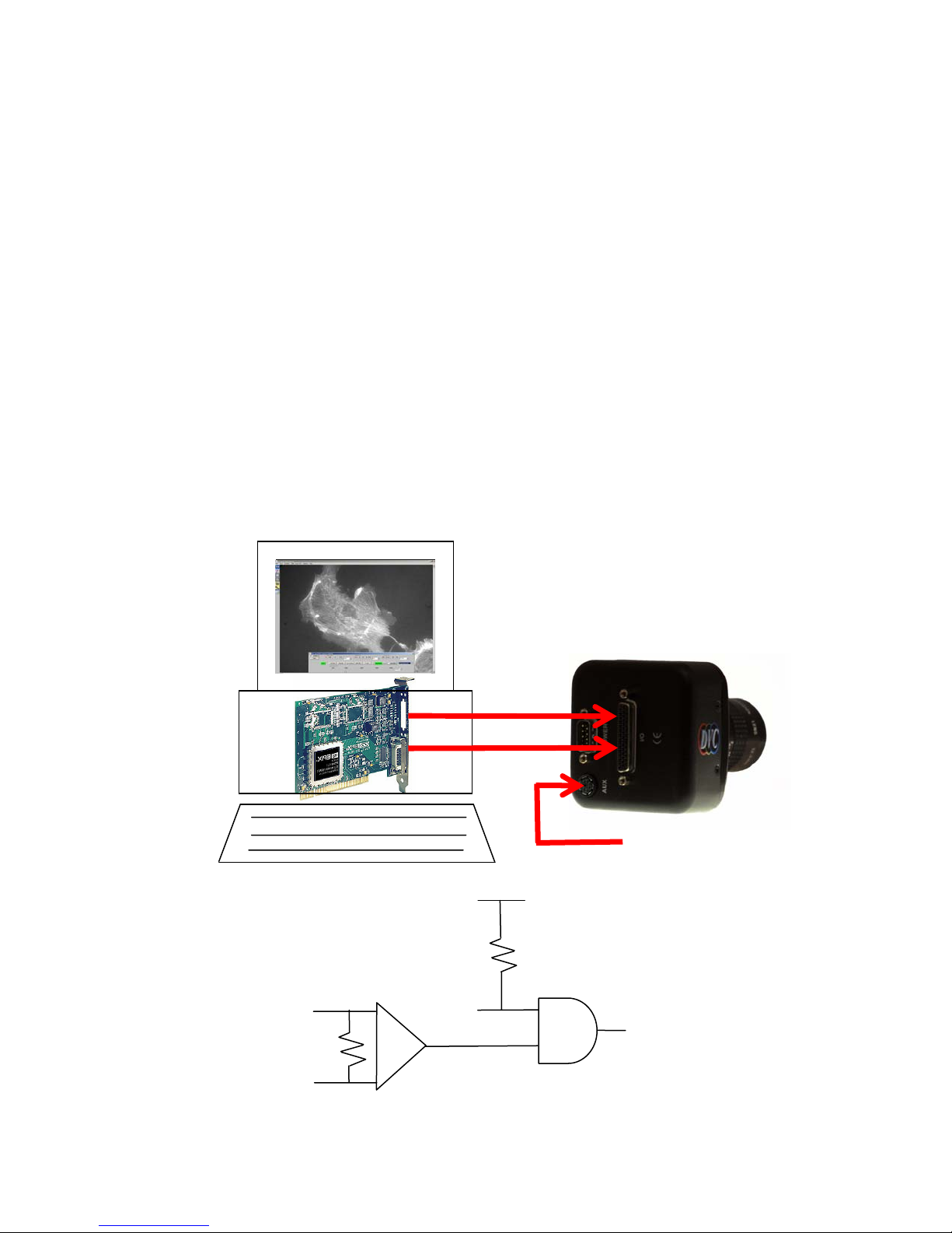
7.4.1 Dark Current Reduction in Ultra Long Exposure mode
The DVC 1412A Cameras incorporate a hardware dark current reduction technique in
ULT mode, frequently called “diode glow reduction.” “Diode glow” refers to areas in the
image that have elevated dark current due to active circuitry on the CCD chip, detectable
only in very long exposures. The DVC 1412A cameras employ a proprietary technique
that results in a 10x reduction of “diode glow” in the ultra long exposure mode.
In software applications such as DVCView, developers may choose to design a single “exposure”
slider bar for long exposures. When the exposure is less than eg. 60 sec, the NFR mode may be
used, with an increment of 1 frame time = 1/10 sec. For longer exposures, the ULT mode is
invoked with an increment of 120 frames = 12 sec. The transition between NFR mode and ULT
mode may be transparent to the user; the only real difference between the ULT and NFR mode
from the user’s perspective is the “granularity” of control.
7.5 PULSE DRIVEN EXPOSURE
PDX: Pulse driven exposure (external)
PDI: Pulse driven exposure (internal, one-shot)
PDP: Pulse driven exposure (internal, periodic)
(LVDS differential input
from frame grabber board)
CC1+ / INPUT 1 +
CC1- / INPUT 1 –
Figure 7.5-1: Asynchronous Reset
INPUT 1 +
INPUT 1 –
VRST_INT
(TTL)
VRST_INT (TTL)
+ 5V
CAMERA RESET
(INTERNAL SIGNAL)
27
Page 34

When the Pulse Driven Exposure mode is selected, the duration of exposure is set by the user via
the LOW duration of an externally generated pulse. A falling edge of the pulse clears the imager
and initiates exposure, a subsequent rising edge terminates exposure, resets the vertical counter
within the camera and initiates readout of the acquired frame.
This pulse signal may be TTL (VRST_INT) or differential(CC1+ or CC1-) or (INOUT1 + &
INOUT1-); these two inputs are logically AND-ed within the camera, therefore one of them should
normally be HIGH if the other one is to be used. There are no prescribed limits to the LOW
duration; therefore this mode affords the user the most flexibility in terms of controlling the
duration and the instant of exposure. For example, application software can be written to directly
drive the camera between long and short exposures without any latency; some application
developers choose to use the PDX mode as the sole camera mode, since this can control long and
short exposure easily by controlling a single signal. The max rep rate of the driving pulse in the
1412 is limited to 1/(frame period + exp).
In order to maintain synchronization with a frame grabber, the pixel clock and enable line signals
are un-interrupted during exposure and subsequent readout. The enable frame signal, however, is
set "low" during exposure and goes "high" only during readout to signify that the accumulated
frame is being read out and may be captured by the frame grabber. This is shown graphically in the
timing diagram below.
NOTE: The frame grabber should be capable of sustaining long periods of time without receiving
an Enable-Frame signal.
PDI and PDP are special cases of the Pulse driven exposure mode, in which the camera
microprocessor is used (via the TIL & TIH cmd) to drive the reset pulse. These modes are of
limited use except when the frame grabber does not have a well defined method of generating
exposure pulses.
Figure 7.5-2: Pulse driven integration mode, showing long/short exposure with minimum latency
VRST_INT (TTL) or INOUT1 (LVDS)
ENABLE FRAME
INTEGRATION PERIOD
Pulse Driven Integration Mode
1/10 sec
INTEGRATION
1/10 sec
PERIOD
7.6 BINNING
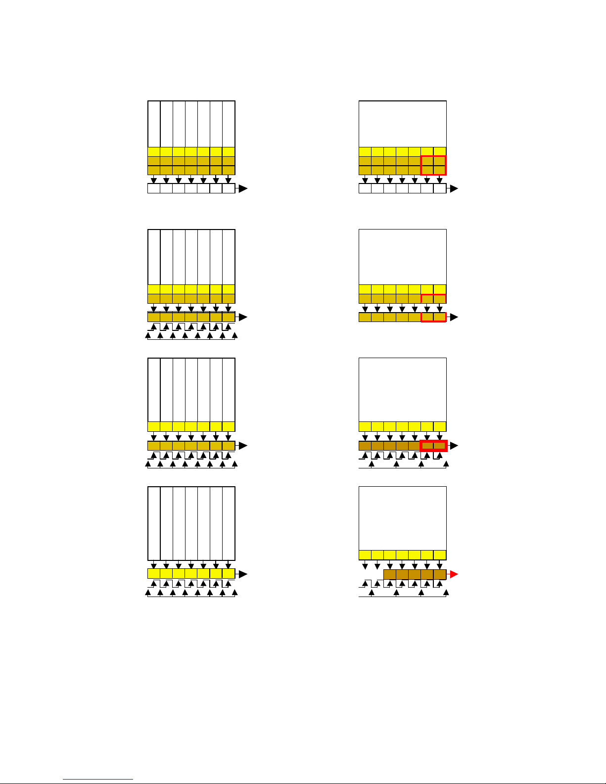
Binning is a feature of the camera that allows the user to trade-off camera resolution in favor of
frame rate and sensitivity. When one of the binning modes is selected, a selected number of
contiguous pixels is treated as one “super-pixel”. This is illustrated below, shown in the bin 2x2
case. By means of transferring two lines into the horizontal shift register, pixels are summed
vertically. These vertically summed pixels are then clocked out to the detection mode without the
usual intervening reset gate signal.
28
Page 35

Command Code Description Frame Size Frame Rate
BIN 11 1 x 1 binning 1392(H) x 1040(V) 10.2f/sec (normal mode)
BIN 21 2 x 1 binning 1392(H) x 520 (V) 20f/sec
BIN 22 2 x 2 binning 696(H) x 520(V) 20f/sec
BIN 44 4 x 4 binning 348(H) x 260(V) 39f/sec
BIN 88 8 x 8 binning 174(H) x 130(V) 68f/sec
Table 7.6-1: Binning commands
29
Page 36
Normal mode (1x1) vs. Binning mode (2x2)
CCD Array
CCD Array
Shift Regis ter
Shift Regis ter
H-shi ft cl ock
Reset Gate
Shift Regis ter
H-shi ft cl ock
Reset Gate
CCD Array
CCD Array
Charge
Detec tion
Node
Charge
Detec tion
Node
Charge
Detec tion
Node
Shift Regis ter
Shift Regis ter
Shift Regis ter
H-shift clock
Reset Gate
Charge
Detec tion
Node
CCD Array
Charge
Detec tion
Node
CCD Array
Charge
Detec tion
Node
CCD Array
Charge
Detec tion
Node
Shift Regis ter
H-shift c loc k
Reset Gate
CCD Array
Charge
Detec tion
Node
Shift Regis ter
H-shi ft cl ock
Reset Gate
Figure 7.6-1: Bin 2x2 case
In the above figure, the pixels marked by the heavy border, are read out as one “super-pixel” value.
The binning mode of the camera is set via the BIN command. There are five valid arguments to this
command {11, 21, 22, 44, 88}. When one of these commands is issued by the host-side software,
the mode control bits are set as shown in the table for 2µsec. The mode control bits then revert to
the setting (1 x x x) just prior to the binning command.
30
Page 37

7.6.1 Binning and Shutter:
The following table is provided as a guide for calculating the shutter mode exposure values that
apply in the different binning modes.
The shutter setting for binning modes needs to be shifted with an offset, in order to get the desired
amount of exposure:
mode no exposure 1_line 2_line max line
1x1 0 1 2 1043
2x2 520 521 522 1043
2x2 520 521 522 1043
4x4 780 781 782 1043
8x8 910 911 912 1043
7.6.2 Binning and Bayer Pattern Color Filter Arrays
When binning is performed within the CCD, e.g. in the BIN 2x2 mode, the charge from a 4-pixel
quad made up of 2-horizontal and 2-vertical pixels is collected into one CCD horiz-shift-register
element. The charge value that is read out therefore corresponds to a summation of the 4-pixel
quad.
P11 + P12
+
P21 + P22
--------------1-data-value
---------------
In this mode, the user trades off resolution for frame rate and sensitivity.
In a Bayer-filter color camera, the 2x2 binning mechanism described above creates a quad
summation which results in R+G+G+B value.
This R+G+G+B value does not represent any meaningful color information; however, it may be
used as a luminance value. Application developers may use BIN 2x2, BIN 4x4 or BIN 8x8 modes
(in a color camera) to create a fast monochrome image during focusing, fast object/image
manipulation in the field-of-view etc. and then revert to a full-resolution 12f/s color image after
determining an image of interest.
R11 + G12
+
G21 + B22
--------------1-data-value
---------------
31
Page 38
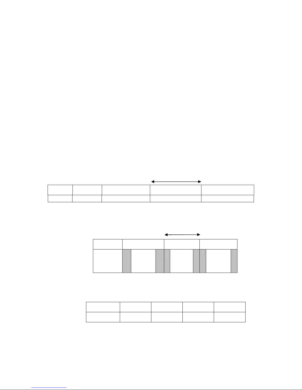
7.7 Sub-array / Region of Interest (ROI )
)
In many applications, users wish to designate a particular Region of Interest (ROI) within the entire
image.
The ROI feature of the DVC-1412 allows the definition of a band of pixel-rows that are selected
for readout. The CCD is then fast-scanned through the un-selected areas, allowing for a faster
overall frame rate of only the selected area. Since the faster frame rate is created by the selection of
fewer pixel-rows, only the vertical “Y” parameter needs to be set within the camera.
The application software may also allow the designation of unwanted columns (for example, by
allowing the user to draw a ROI box around the selected region. In that case, the application may
“blank” the unwanted columns for a convenient presentation to the user. However, the de-selection
of columns from readout has no effect on the frame rate.
7.7.1 Functional Description
Under normal conditions, every pixel of the CCD array is read out to create an image frame for
display. The camera images, transfers, and read-outs. With the 1412, there is a 1/10 second
exposure, occurring concurrently with 1/10 second read-out. Thus, while readout N-1 takes place,
exposure N is also happens.
Normal Exposure
Readout
Exposure EXP
array /
Readout
ROI
(16XN)
ROI 512 X N 256 X N 64 X N 16 X N
Table
Frames/sec 19 32 70 100
100 mSec (10 f/s)
EXPN EXP
RDT
RDTN RDT
N-1
10 ms (100 f/s
EXP
N
F
A
S
T
RDT
NORMAL
N-1
F
A
S
T
EXP
N+1
EXP
N+1
RDTN
RDT
N+L
N+1
N+L
N+1
Sub-
32
Page 39
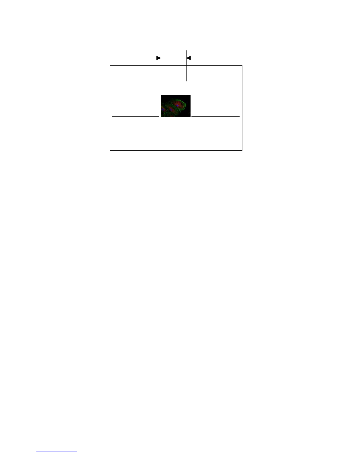
trimmed in display with software
unwanted - fast scan
wanted
[normal scan]
wanted
[normal scan]
unwanted - fast scan
7.7.2 Advantages
ROI allows faster frame rate without compromising spatial resolution. The benefit of ROI is that
fewer lines are scanned instead of scanning all lines of the CCD. Thus, a higher number of frames
per second are achieved. Instead of getting 10 frames per second, the user could view the selected
pixels at full-resolution at a faster frame rate.
7.7.3 Disadvantages
The downside of ROI is that as one reduces the ROI, the frame duration is lowered leading to lower
exposures per frame, causing less image brightness. For example, if the exposure time went from
1/10 second to 1/100 of second, the image would be a significantly lower duration of
exposure/frame.
7.7.4 What can be done to overcome this disadvantage?
One can sacrifice the lack of brightness or can compensate for brightness in another way. This can
be done by making the lamp brighter in a microscope or by opening-up the iris of a lens. Thus,
ROI is especially advantageous where one has control of the light
7.7.5 What applications should ROI be used for?
In applications such as bright field microscopy and single molecule tracking, the user can select an
area of interest and improve the effective frame rate. The Intensicam-1412 is based on the 1412
and is used for low-light images where the user wants speed.
7.7.6 ROI Commands
ROI {0,1} .. {OFF,ON}
BTY yyy .. Bottom Y coordinate; three digit Hex; should be divided by 2 TPY YYY ..
Top Y coordinate; three digit Hex
The Y coordinate starts from the first line to be read out and counts up to 1032. Due to its internal
implementation, BTY needs to be divided by 2. For example:
ROI 1
TPY 100 (H’100=>256)
BTY 100 (H’100=>256*2=512)
Will set an ROI from pixel row 256 to pixel row 512
33
Page 40

In the present implementation, ROI and BIN are mutually exclusive commands. This will be
changed in later versions.
7.8 SLOW SCAN
Slow scan: The read noise of a CCD can be significantly affected by the readout rate. Some users
wish to improve the read noise by slow-scanning the CCD. This is provided in the camera by
means of a clock multiplexer scheme; the user selects which one of the two) clocks is to be used as
the pixel clock.
NOTE: This selection affects all the internal clocks, since the entire timing logic runs on the
selected clock. Therefore, all exposure values etc. will be scaled accordingly.
The slow-scan mode of the camera is set via the SLW command. There are two valid arguments to
this command {01, 02}.
Command Code Description Frame Rate Clock
SLW 01 Fast pixel clock divided by 1 10f/sec 18 MHz
SLW 02 Fast pixel clock divided by 2 5f/sec 9 MHz
Table 7.8-1: Slow-scan mode commands
34
Page 41
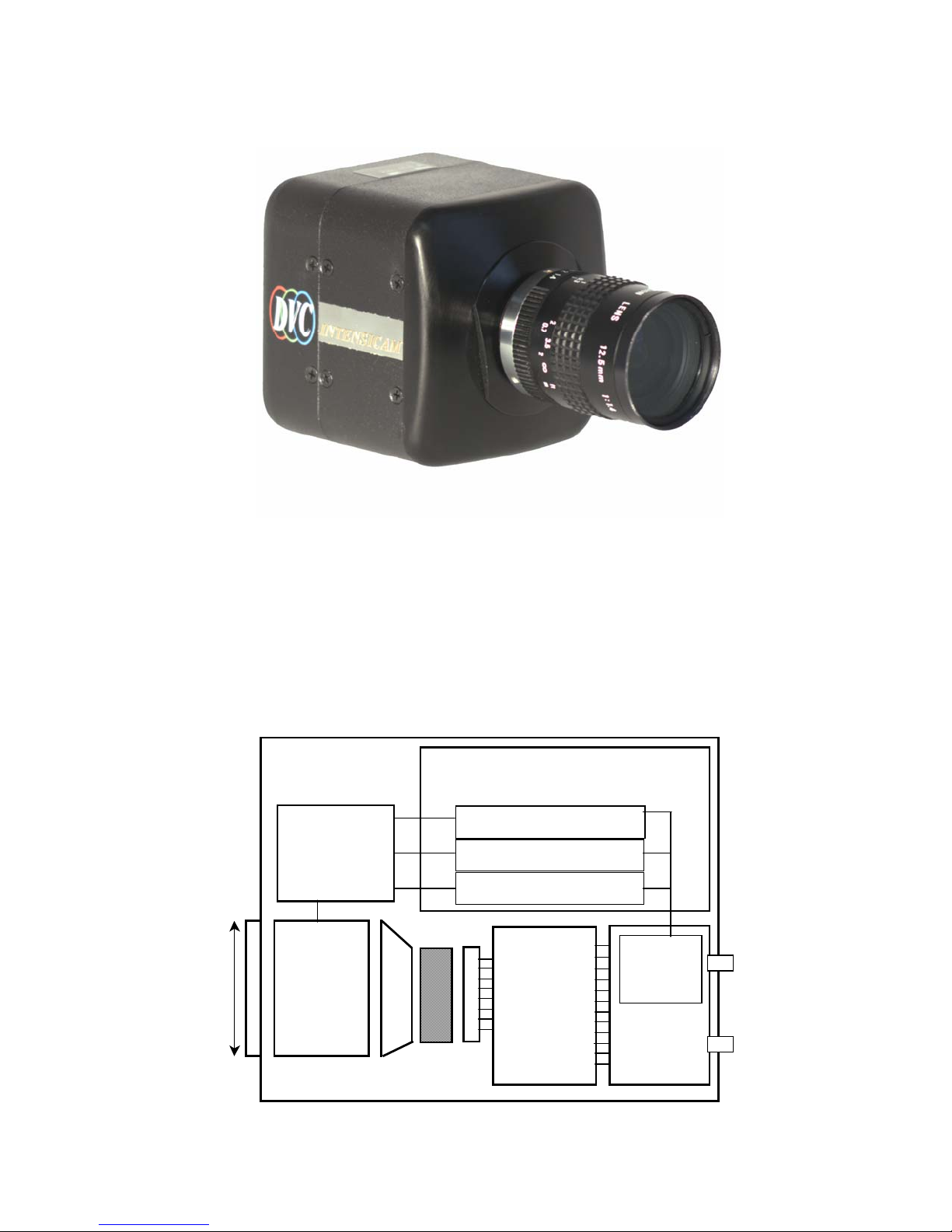
7.9 INTENSICAM-1412
p
r
7.9.1 Introduction
The Intensicam-1412 is a special version of a 1412 camera in which a gated Gen III image
intensifier is fiber-optically bonded to the front surface of the CCD. Due to the high luminous gain
of the Intensifier tube, every incident photon generates thousands of electrons within the tube.
Even under very low-light conditions, this results in a live image on the phosphor of the Intensifier,
which is viewable by the CCD.
7.9.2 Functional Description
Intensifier
Power
Supply
1” format Cmount lens
adaptor
Gated
Gen III
Image
Inte nsifie r
Fiber Optic
Module
Intensifier Control Board
Gain DAC
Pulse Generator
Calibration Control
CCD
CCD Board
CCD Board
Microprocessor
I/O Board
To Host
ute
Com
Camera
Power
Supply
35
Page 42
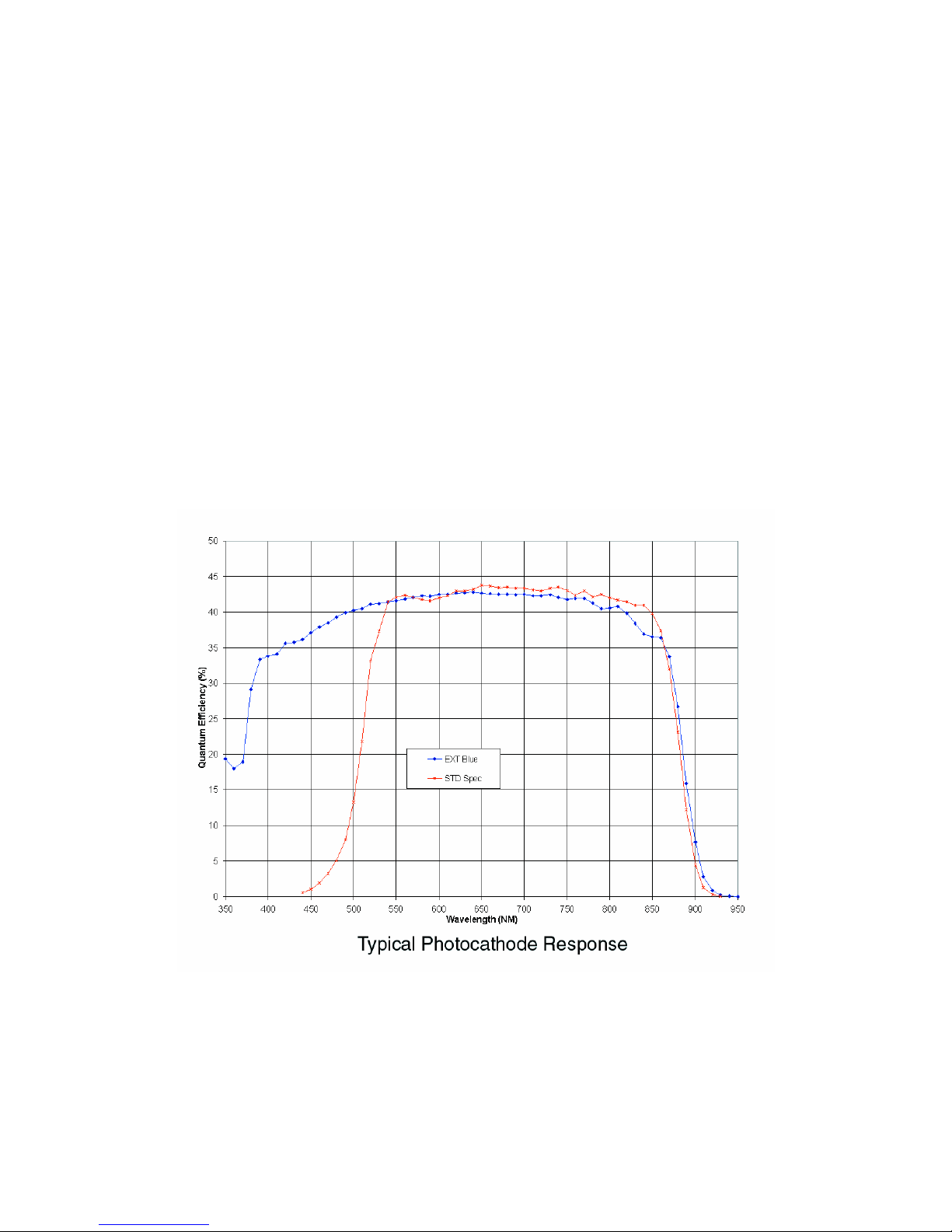
Fiber-optic module: This is used to couple the image that is generated on the phosphor of the image
intensifier to the CCD. Since the optical format of the image intensifier is 1” and that of the CCD
is 2/3”, a taper is used for the reduction.
High voltage power supply: This is used to generate the voltages that are necessary for the
performance of the image intensifier.
Intensifier control board: This board interfaces between the camera I/O board and the high-voltage
power supply. A serial interface is used between the I/O board and the controller chipset.
NOTE: Over-exposure can cause permanent damage to the Intensifier tube internal to
Intensicam}
7.9.3 Spectral Response
Standard and enhanced coatings are available to provide different spectral characteristics (see
Figure 7.8.1). The phosphor of the intensifier (which is fiber-optically coupled to the CCD) emits
in the blue-green part of the spectrum, which is well matched to the peak-response of the CCD.
The spectral response for the standard intensifier (and the extended blue version) are shown below;
enhanced coatings are available upon request.
Figure 7.9-1: Intensicam spectral response
36
Page 43

7.9.4 Intensicam & DVCView
1) In DVCView, there is an "Intensify" check box on the control panel that controls the
intensifier. As long as this box is not checked, the Intensifier is gated OFF (to protect the
camera). Although the camera is connected (and a frames/sec counter is visible in the LHS
of the viewing window), the image will remain black.
2) The user must click on the check box to turn the Intensifier on. {NOTE: Over-exposure
can cause permanent damage to the Intensifier tube that is part of the Intensicam}. It
is the user's responsibility to ensure that the light settings of the microscope or optics are
appropriate for use with this camera. If an overload is detected (in the form of an
overexposed white image), the user should IMMEDIATELY uncheck the box to turn OFF
the Intensifier. Then, after readjusting the optics, the process may be repeated until suitable
viewing conditions exist.
For further instructions on using DVCView, please refer to the DVCView User Manual,
available at the DVC website: www.dvcco.com
37
Page 44
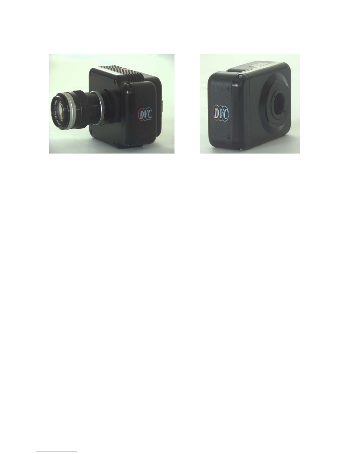
7.10 MULTI-SPECTRAL OPTION
Figure 7.10-1: Cooled (left) and non-cooled (right) multi-spectral cameras.
A module equipped with a four-position multi-spectral filter wheel is integrated within a modified
monochrome DVC-1412 camera housing (both TE-cooled and non-cooled versions are available).
The filter module can be supplied with high-quality CLEAR/IR-CUT, RED, GREEN, BLUE
optical filter elements or with special application set. It is designed such that the filter elements
can easily be removed and replaced with the users choice of standard 1” filters. The entire module,
comprising of the wheel, filters, motor and electronics can easily be removed from the camera
housing, to facilitate the use of different multispectral filter sets to match the user’s applications. A
tool is provided to facilitate the removal and replacement of filter elements on the wheel.
The wheel is indexed to the "Home" position, which nominally coincides with the CLEAR/IR-CUT
optical filter. A serial command set is used to step the filter wheel through its four positions, which
place one of the four filter elements in the optical path of the CCD. Once a particular optical filter
is positioned in front of the CCD, the user may invoke any of the camera modes (discussed in this
manual) to set up parameters such as gain, offset, exposure and mode. This allows users to set up
sequential multi-spectral exposures to match the requirements of the application.
7.10.1 Optical Considerations
The standard C-mount lens system specifies a fixed distance of 0.69 inches between the lens mount
reference surface and the image plane. Because the filter wheel assembly must utilize some of this
space between the lens and CCD, the distance between the lens mounting surface and the lens rear
element can be no greater than 0.18 inches, as shown in figure 7.10-2. Important: if this distance
is exceeded, the rear element of the lens will contact the filter wheel assembly and could cause
damage.
7.10.2 Software considerations
In R-G-B color applications, three individual color plane images are taken sequentially; these color
plane images are usually superimposed via software to create a high-resolution full-color image.
There are several factors involved to ensure high-quality images with such a sequential system:
38
Page 45
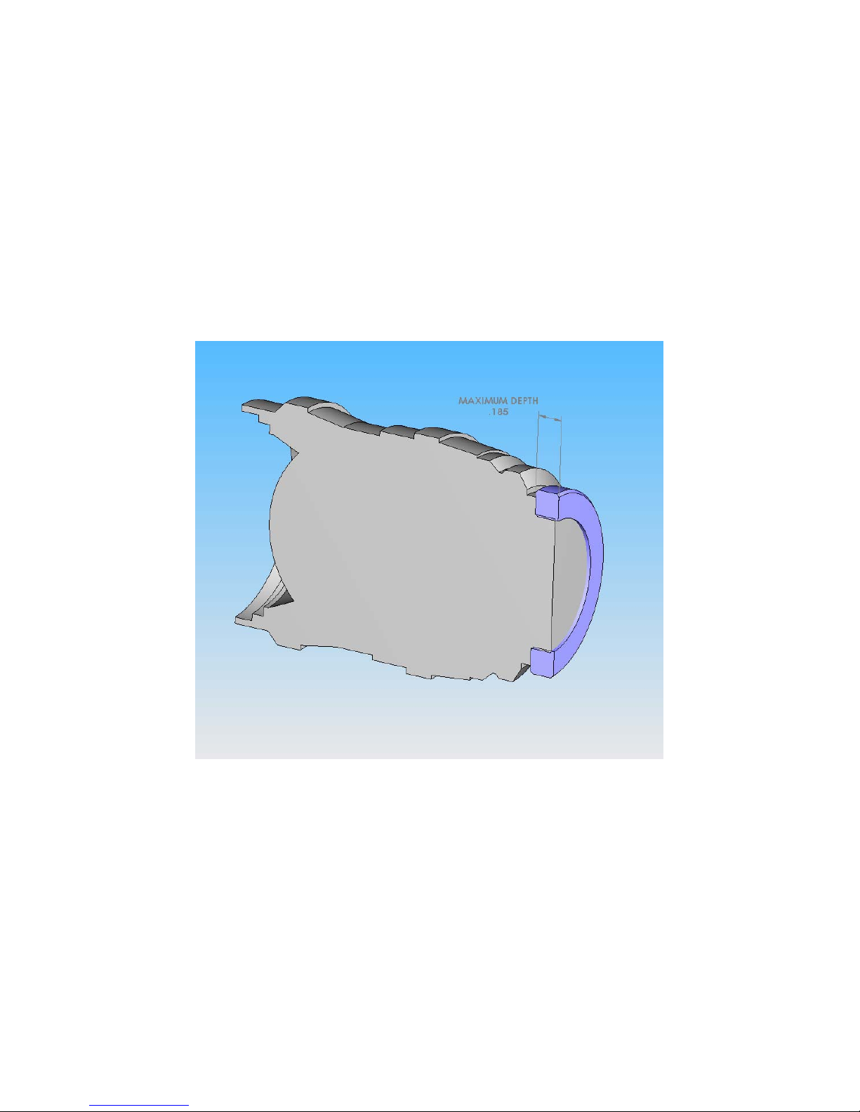
7.10.2.1 Image Registration
The three color planes should be precisely aligned; misregistration of the color planes will result in
image artifacts ranging from loss of resolution to misaligned edges. The camera should be securely
mounted during use to prevent misregistration.
7.10.2.2 Auto White Balance
In order to make the white areas in the field of view appear to be white (R=G=B), most software
applications use a calibration scan, in which R, G and B images are obtained to determine the
relative strength of each component. Once the calibration data is obtained, software algorithms are
employed to determine the correct combination of gain/exposure for each color plane in order to
produce a white pixel at the appropriate location in the superimposed image.
Figure 7.10-2: Maximum Lens Depth
39
Page 46
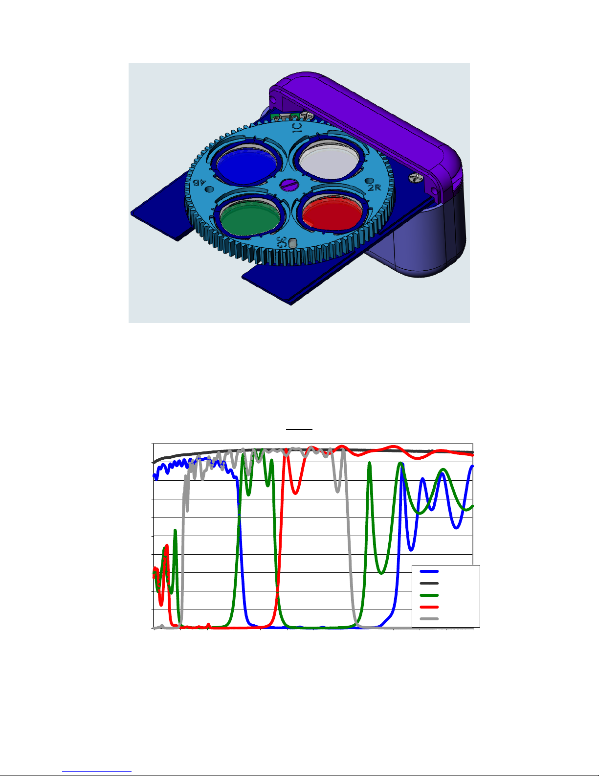
Figure 7.10-3: Color filter wheel moduleSpectral Response
NOTE: the spectral response curves shown represent the R, G, B, and clear configuration of the
filter-set. Since the camera design allows the user to insert any filter-set of choice, this data may
not be valid for user-configured cameras.
Filters
100
90
80
70
60
50
40
% Transmission
30
20
10
0
Blue
Clear
Green
Red
IR
950900850800750700650600550500450400350
Wavelength (nm)
40
Page 47

7.10.3 Module Removal & Change of Filters
Estimated Time of Removal: 2-3 minutes
Materials Needed: 3/32" socket head drive, dry air bottle
Important Considerations:
• Use care not to put fingerprints on the filter surfaces. Wear rubber gloves while
performing this operation
• Filters with holders & glass thickness up to 5mm are acceptable in 25 mm diameter
aluminum frame
• The housing that holds the filter should be 3.5mm - 5.5mm thickness and 25.4mm in
diameter.
• For RGB, the filter disk is numbered 1C, 2R, 3G, 4B (where C = Clear, R = Red, G =
Green, B = Blue). The filters must be placed in this order
• When the camera is turned on, it will set itself such that, position 1 is the default or home
position in front of the lens
41
Page 48
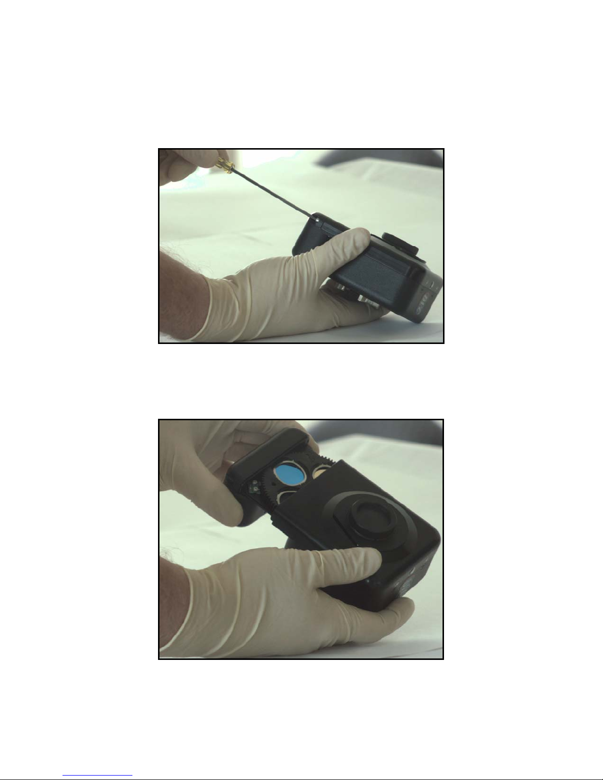
7.10.3.1 Removing the Filter Wheel Module
1) Remove the two 4/40" X 3/8" Allen-head screws which retain the module.
a. These screws are the only silver-colored screws on the camera.
b. Use a 3/32" socket head drive to remove the screws.
2) Disengage the filter wheel module.
a. Pull firmly to remove the module from the camera.
b. There are no connectors to disengage. The module will simply slide out.
42
Page 49
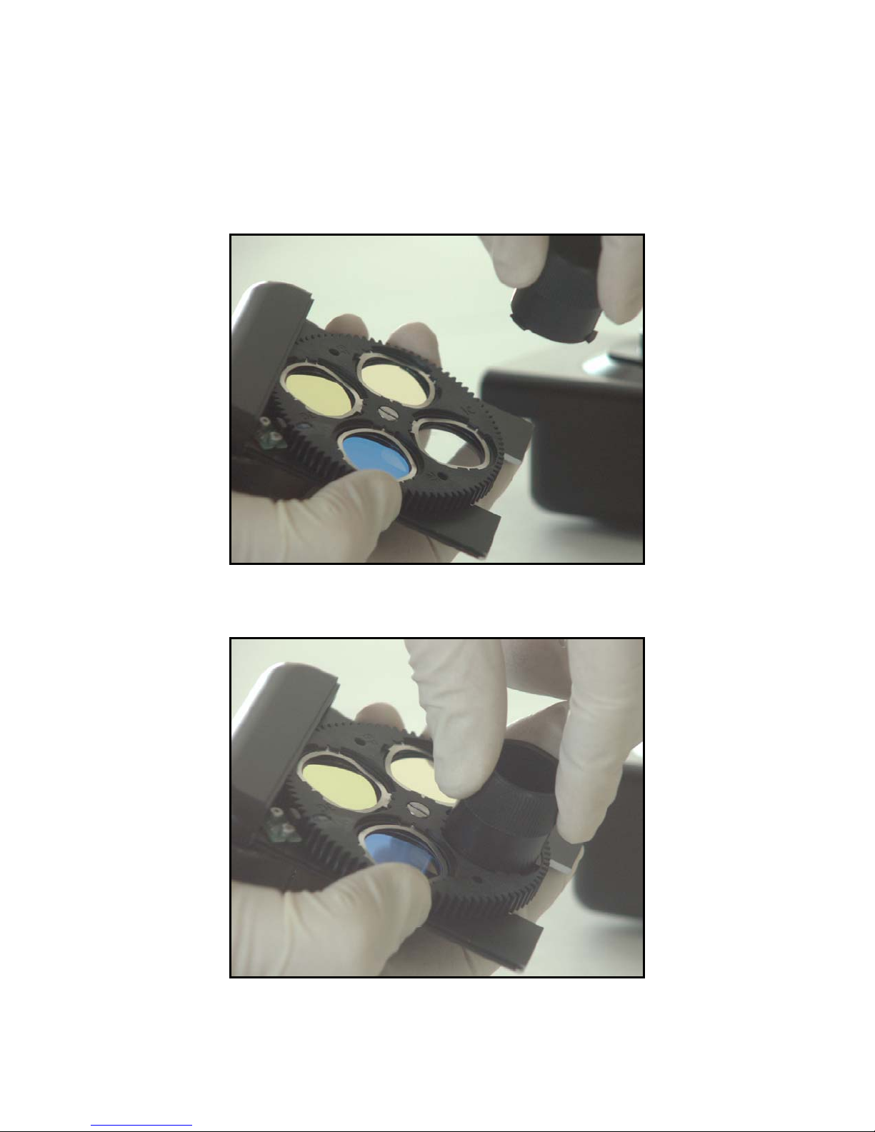
7.10.3.2 Removing the Filter
1) Using the filter-spring removal tool, grasp the tool with one hand, while holding the filter with
the opposite hand.
2) Align the tool on top of the filter spring.
43
Page 50
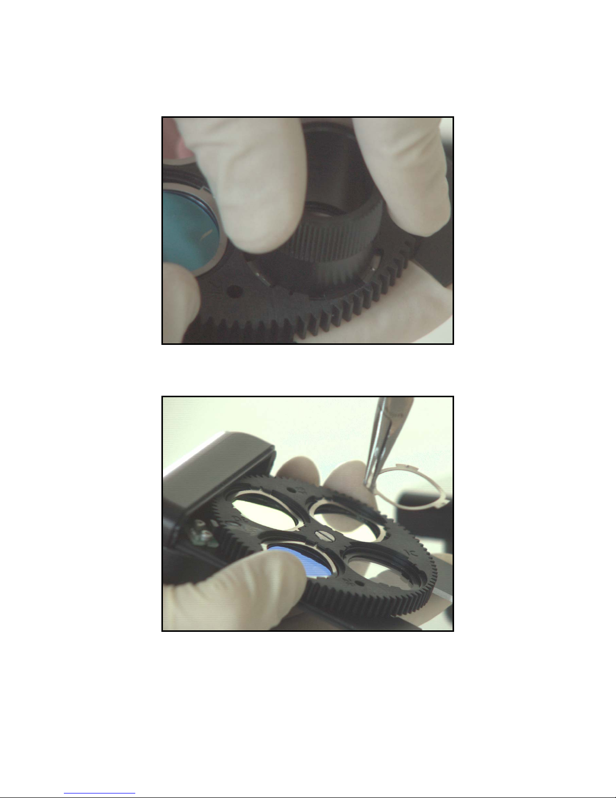
3) Push and turn the tool while compressing the spring, so that the tabs on the tool go underneath
the protrusions holding the filter spring. This process will disengage the filter. Rotate the tool
until both the spring tabs and the tool are clear of the protrusions.
4) Remove the tool. Use forceps or fine pliers to remove the spring.
44
Page 51
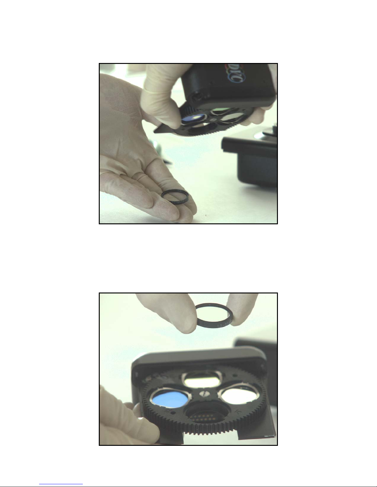
5) Place a clean surface lens paper where you want the filter to fall upon. Turn the module up
side down. This will cause the filter to fall out.
7.10.3.3 Installing Filters
1) Identify the filter surface with a lip. This surface should face the bottom of the wheel.
45
Page 52
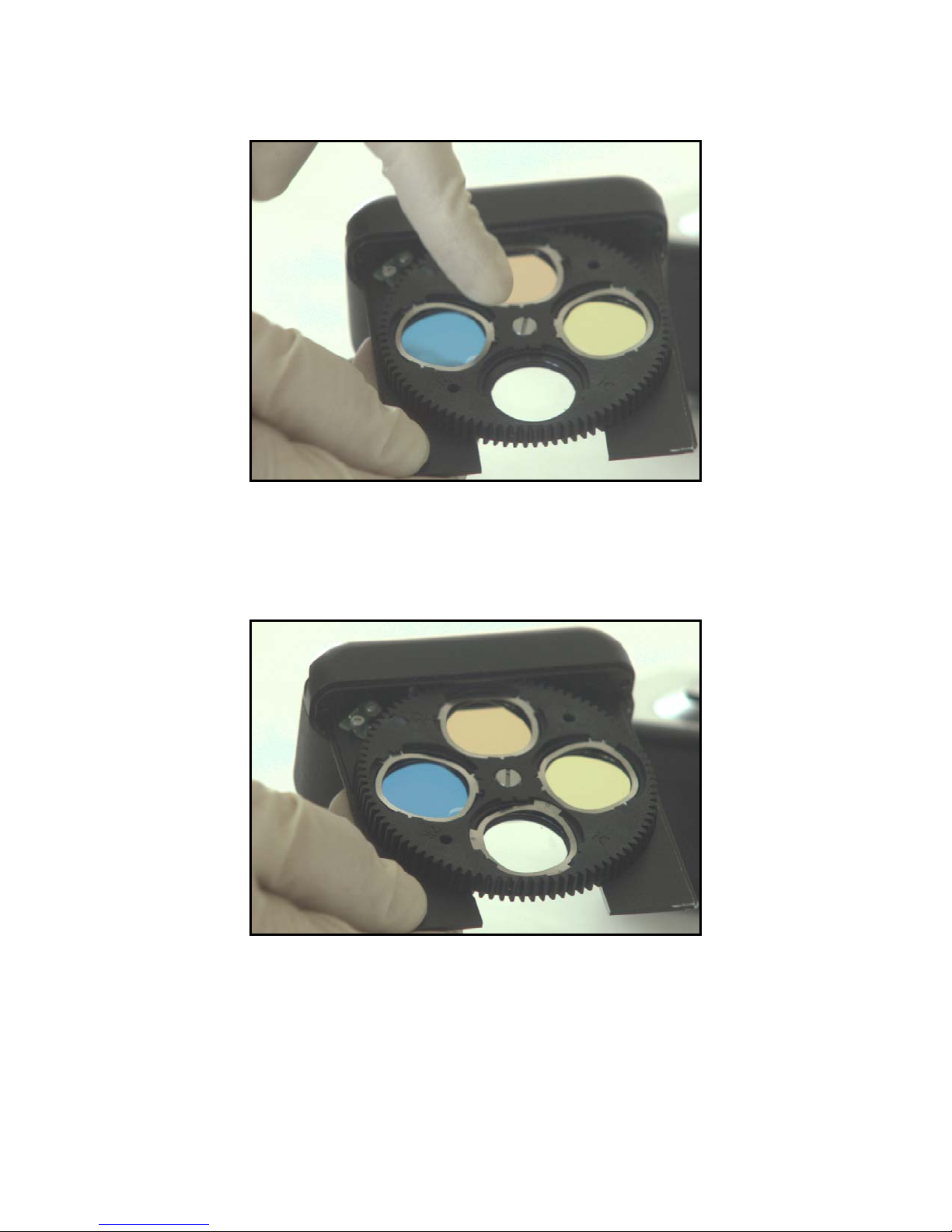
2) Drop the filter into the slot.
3) Identify the spring surface with the dot protrusions. The dot should face the top.
4) Drop the spring into the slot above the filter.
46
Page 53
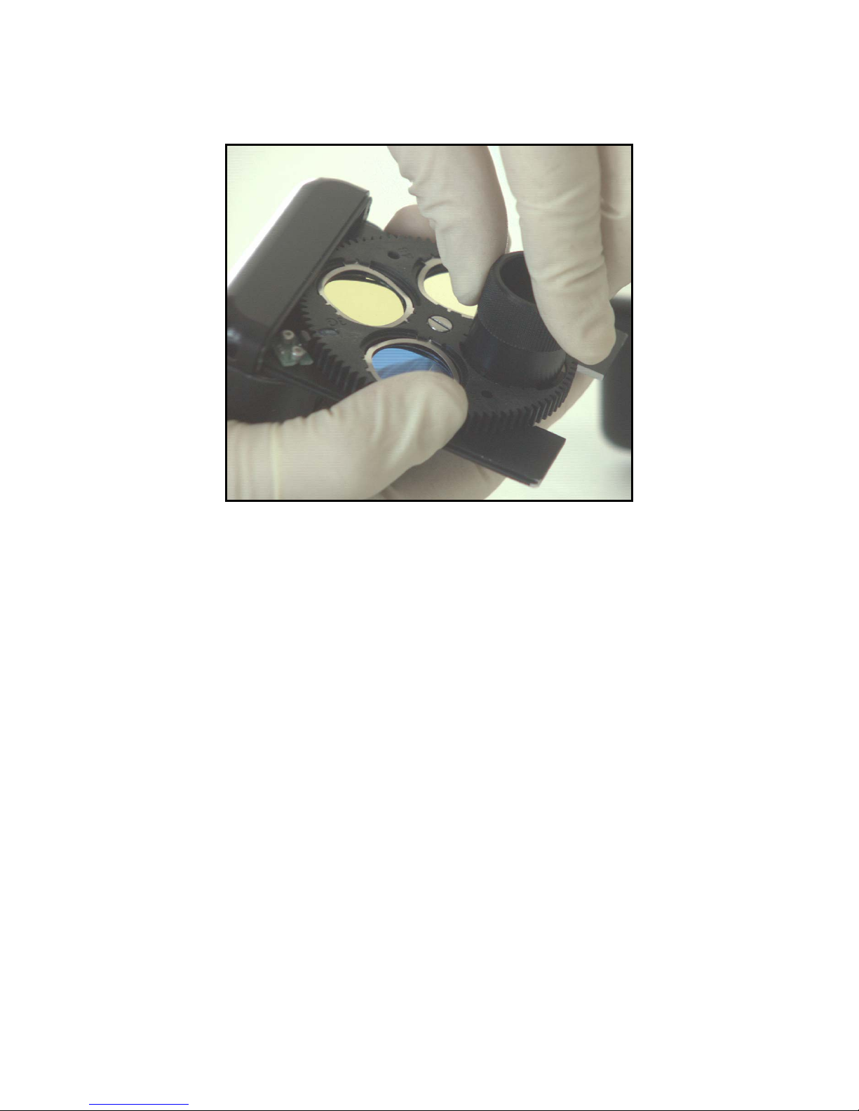
5) Using the filter-spring removal tool, compress the spring.
Turn the tool until the dots line up. Remove the tool.
47
Page 54
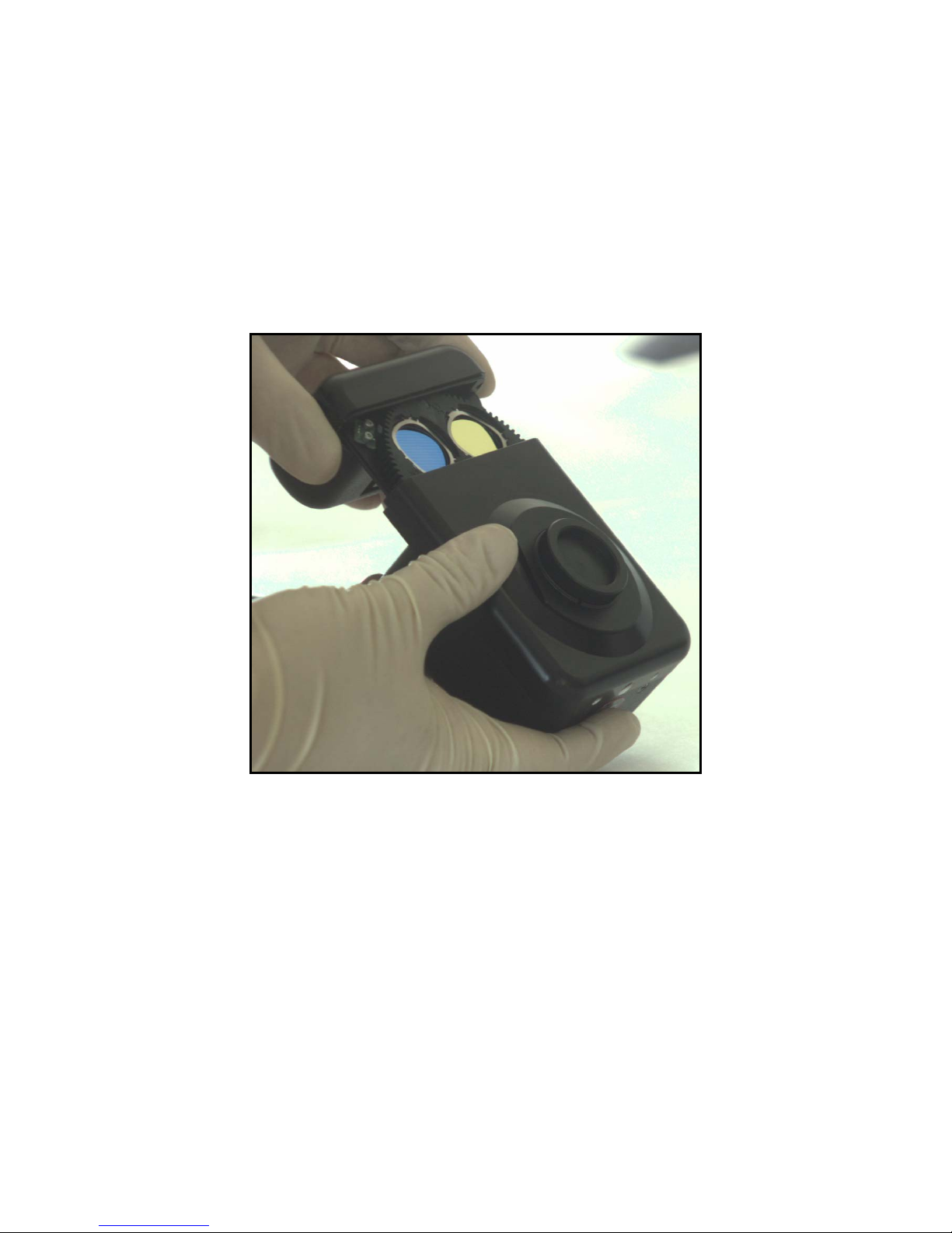
7.10.3.4 Inserting the Filter Wheel Module in the Camera
1) Clean the filter wheel with low pressure, dry air to remove any dust and contaminants. As with
any optical surfaces, blow at an angle to avoid driving particles directly into the surface at high
velocity. Use a clean, dry (preferably brand-new) camel-hair brush (like those used by
photographers) to gently remove any remaining particles.
2) Engage the module with the slots in the camera.
3) Slide the filter wheel module back into the camera. Push the module all the way in.
4) Install the two 4/40" X 3/8" Allen-head screws with a 3/22 socket head tool.
48
Page 55
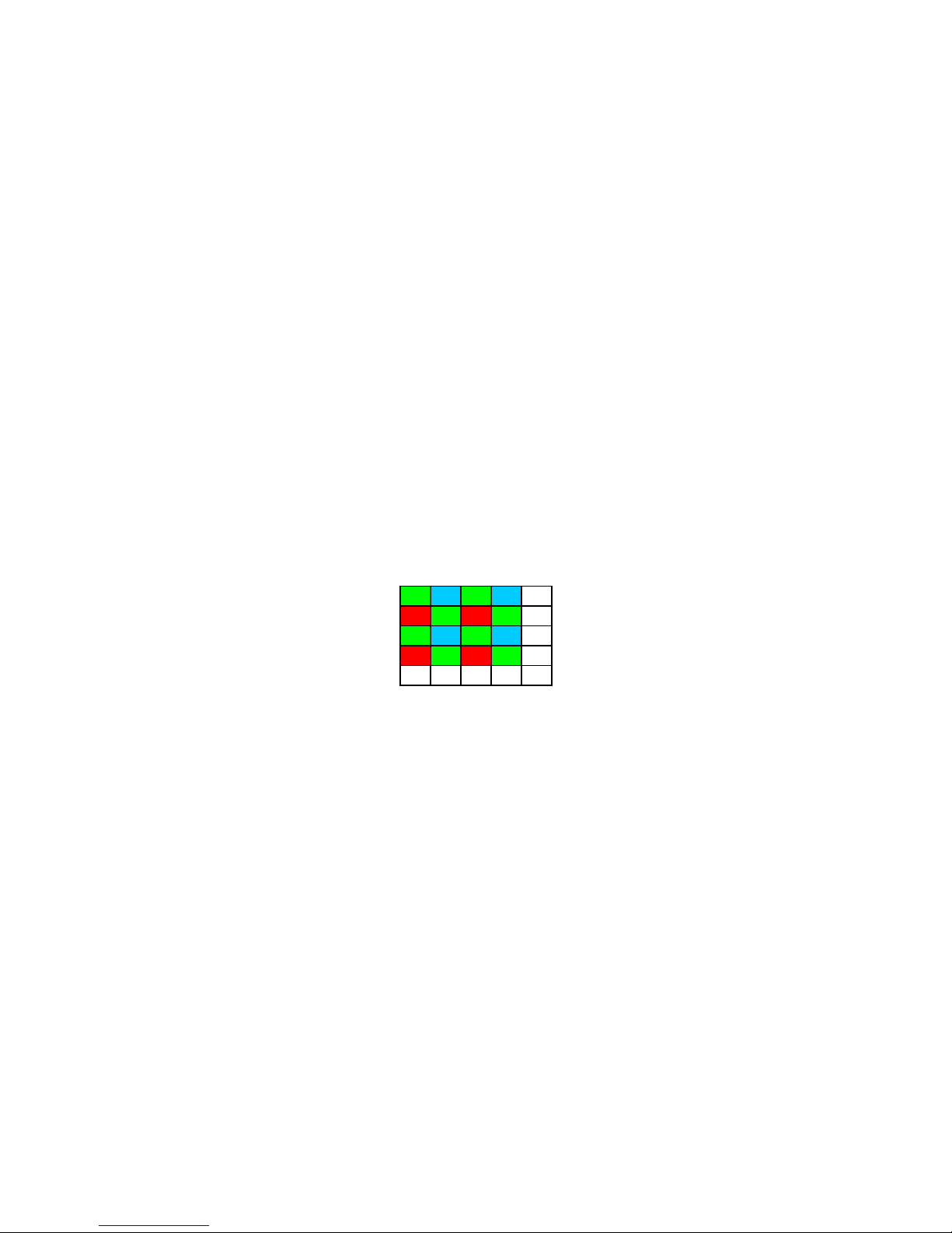
8 APPLICATION NOTES
8.1 BAYER FILTER DECODING ALGORITHM
8.1.1 Introduction
The following information is provided to assist software developers to create a high-resolution
color image from the digitized data that is provided by the DVC-1412C Camera.
1) The electronics within the camera are the same for the monochrome as well as for the R-G-B
version of the camera. For this reason, all the timing signals, including digitized video data, clock,
enable-line and enable-frame are the same for both cameras. Also, all modes of operation that are
described for the monochrome version of the camera apply to the R-G-B version. These modes
include the electronic shutter modes, asynchronous reset mode, and pulse driven integration modes.
2) The color-filter-array (CFA) of the color imager follows the commonly used "Bayer pattern".
This pattern (shown below) is based on the premise that the human eye derives most of the
luminance data from the green content of a scene; and it is the resolution of this luminance data
that is perceived as the "resolution" of an image. Therefore, by ensuring that more of the pixels are
"green", a image of higher perceived resolution can be created--compared with an alternating R-GB color filter array with equal numbers of Red, Green and Blue pixels.
GBGB ..
RGRG..
GBGB ..
RGRG..
::::::
Figure 8.1-1: Bayer Pattern CFA
8.1.2 Color Pixel Processing
The following steps are required for processing the color pixels
8.1.3 White Balance
Depending on the "color temperature" of the light source, a white object may generate different
values for its R, G and B pixel values. For example, when the camera is pointed at a uniformly
diffused white object that fills the entire field of view, the resulting R, G and B values may form
the following matrix:
49
Page 56

300 200 300 200 . .
110 300 110 300 . .
300 200 300 200 . .
110 300 110 300 . .
: : : : : :
R=110, G=300, B=200 R=200, G=300, B=110
Figure 8.1-2: Examples of Bayer Pattern values for fluorescent and incandescent light
Both cases require correction, because a white object should have R=G=B data values. The
simplest correction would involve "equalizing" the data - if the Green pixel values are kept
unchanged and the Red and Blue pixel values are multiplied by appropriate "gain" coefficients.
In the case of the "fluorescent lighting" example, Red Gain (Rg) should be 300/115 = 2.6 and Blue
Gain (Bg) should be 300/200 = 1.5
In the case of the "incandescent lighting" example, Rg (or Red Gain) should be 300/200 = 1.5 and
Bg should be 30/115 = 2.6
As shown in the above examples, the Rg and Bg coefficients depend on the type or the color
temperature of the illumination that is used. Therefore, a "white balance" operation is required each
time that the scene illumination or color temperature is changed.
The procedure for a white balance operation is as follows:
300 110 300 110 . .
200 300 200 300 . .
300 110 300 110 . .
200 300 200 300 . .
: : : : : :
(fluorescent lighting)
(incandescent lighting)
• the software instructs the user to point the camera at a uniform white object e.g. a
sheet of white paper.
• the software instructs the user to press the "white-balance " button.
• the software examines the ratios G/R and G/B and determines the average value of
Rg and Bg over a predetermined region. It is usually a good idea to keep the ratios
reasonably small.
• the software then stores the computed average Rg and Bg values and uses them as
coefficients to generate color corrected Red and Blue pixel values from the "raw"
Red and Blue pixel values.
In some applications, it may be possible to store some frequently observed combinations of Rg and
Bg to simplify this operation. For example, if the camera is used under the same lighting conditions
at all times, the user should be able to perform the white balance operation once and then store the
Rg and Bg values. A typical software user interface might have three choices under Preset White
Balance options: "Typical Fluorescent", "Typical Incandescent" and "User Setting."
50
Page 57
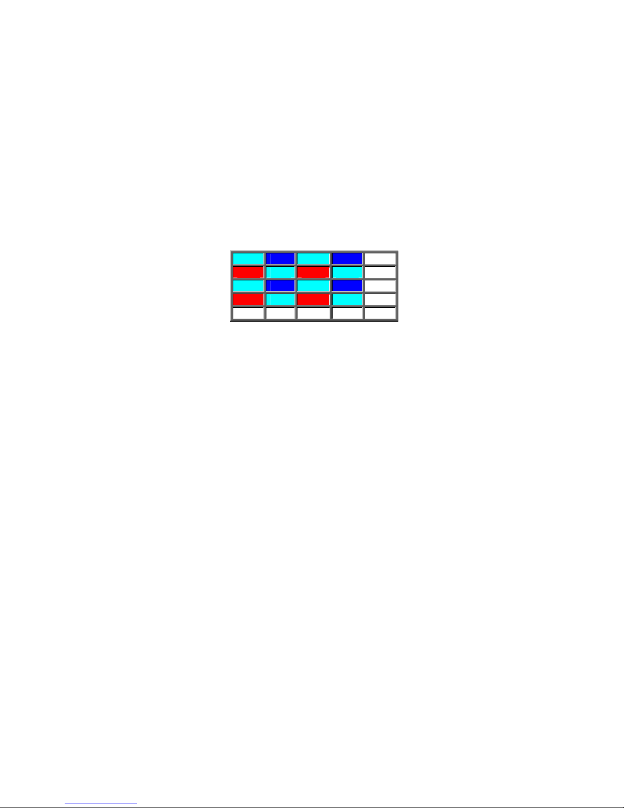
8.1.4 Gamma Correction
In order to compensate for the non-linearity of monitors, a gamma correction curve needs to be
applied to the color corrected digitized pixel values. A default value of 0.6 may be provided,
although in some applications, this may need to be a user-supplied number.
8.1.5 Color Coding
For each digitized pixel value (after color correction AND gamma correction) it is necessary to
generate the remaining two values to complete that pixel’s representation in the R-G-B color space.
This can be done in several ways - it might be a good idea to provide all the following
implementations and then allow the user to select the one that best suits the application.
In the following example, the G11, B11 … represent color-corrected and gamma-corrected
digitized pixel values. Several different color-coding algorithms are possible:
Figure 8.1-3: Bayer Pattern CFA (color coding example)
G11 B12 G13 B14 . .
R21 G22 R23 G24 . .
G31 B32 G33 B34 . .
R41 G42 R43 G44 . .
: : : : : :
8.1.6 Suggested Algorithm
"Green pix" PIX22 = Avg(R21, R23); G22; Avg(B12, B32)
"Red pix" PIX23 = R23; Avg(G13, G22, G33, G24); Avg(B12, B32, B34, B14)
"Blue pix" PIX32 = Avg(R21, R41, R43, R23); Avg(G31, G42, G33, G22); B32
For pixels on the edge of the imager, the following algorithm can be used:
PIX11 = R21; G11; B12
LHS column
PIX21 = R21; Avg(G11, G22, G31); Avg(B12, B32)
PIX31 = Avg(R21, R41); G31; B32
Top row:
PIX12 = Avg(R21, R23); Avg(G11, G13); B12
PIX13 = R23; G13; Avg(B12, B14)
A similar approach can be taken with pixels on the bottom row and the RHS column.
51
Page 58

9 Serial command interface definition for DVC-
r
1412Acameras (LVDS and CameraLink Cameras)
9.1 INTRODUCTION
The following is a definition of the serial control interface for the DVC-1412A cameras.
Communication with the 1412A LVDS cameras can be carried out via a communication program
(such as Windows HyperTerminal) or within a larger program, such as C-View. 1412A
CameraLink cameras require a CameraLink serial communication utility, usually provided by the
host interface board manufacturer.
.
9.2 COMMUNICATION PROTOCOL
Serial communication protocol: the camera uses a full duplex UART type asynchronous
system, using standard non-return-to-zero (NRZ) format (one start bit, eight data bits, one stop
bit, no parity). The baud rate is fixed at 9600. The character code is based on the ASCII
standard. Character flow protocol: None
Command Syntax: the camera will recognize a command as three command characters,
followed by a space character, followed by an argument that consists of one or more characters,
ended by the carriage return character.
Query Syntax: the camera will recognize a query as three command characters followed by the
question mark character, then ended by the carriage return character. The camera responds to a
query with three command characters, followed by a space character, followed by an argument
that consists of three characters, then ended by the carriage return character.
Error messages: the camera responds to an erroneous command or query in one of three possible
ways:
ERROR MESSAGE EXPLANATION
E-SYN
E-ARG
E-XMT
E-HRT
The camera cannot understand the command
The camera can understand the command, but the argument is either out-ofrange or not understood e.g. an alpha character embedded in a numeric string
The camera detects a transmission error e.g. buffer overflow, parity o
framing.
The HRT command was issued in a mode in which Hardware Reset is illegal.
9.3 CAMERA CONTROLS
The camera has the following parameters that can be controlled or queried via the serial port:
9.3.1 Gain
This parameter is supplied by the host PC as a three digit hexadecimal data argument to the
command GAI. A gain command with the syntax "GAI 298" would set the gain to the
maximum value.
1) The defult Gain value is 0x0BB corresponding to the 0dB point.
52
Page 59

2) Software designers may wish to design a gain control based on the following table.
The gain is linear in dB with respect to the hex value:
Hex Gain (dB)
0x000 -8.8
0x0BB 0.0 (power-on default)
0x298 +22.4
Table 9.3-1: Gain Table
9.3.2 Offset (or black level)
This parameter is supplied by the host PC as a one-digit hex data argument to the command.
An offset command with the syntax "OFS F" would set the offset to the maximum value.
1) The default offset value is 0x0, corresponding to the 0% point.
2) Software designers may wish to design an offset control based on the following tables:
Hex Offset (%)
0x0 (power-on default)
0%
0xF 6%
Table 9.3-2: Offset Table
9.3.3 Exposure
The 11-bit argument of the EXP command sets the camera exposure. The power-on default value
of EXP is 001. An exposure command with the syntax "EXP 7FF" would set the exposure to the
maximum value. The argument of the EXP command has different increments depending on the
mode of the camera. In high-speed shutter exposure modes, the EXP increments are one
Horizontal-line-period, in NFR mode, the increments are one-frame-periods, and in ULT mode the
increment is 10seconds.
NOTE:
For example, EXP 000 in NFR mode gives 1-frame exposures
EXP 000 in hi-speed shutter modes gives 1-line exposures
EXP 000 in ULT mode gives 120-frame exposures.
the argument of the EXP command is offset by 1 in all modes.
9.3.4 Mode Summary
Description VRST_INT
2:1 Binning; BIN 21 Hi Z
2:2 Binning; BIN 22 Hi Z
4:4 Binning; BIN 44 Hi Z
8:8 Binning; BIN 88 Hi Z
Slow scan, divide PIXCLK by 2; SLW 02 Hi Z
Slow scan, divide PIXCLK by 4; SLW 04 Hi Z
Slow scan, divide PIXCLK by 8; SLW 08 Hi Z
Unlock slow-scan & binning; SLW 01 OR BIN 11 Hi Z
53
Page 60

N
ormal mode with reset Hi Z
N
High speed shutter with discharge (one-shot) Hi Z
High speed shutter without discharge Hi Z
High speed shutter with discharge (continuous) Hi Z
Ultra-long-term exposure Hi Z
"N" frame integration (low speed shutter) Hi Z
Pulse driven exposure (internal, one-shot) Int. ¯¯|____|¯¯ sets exposure
Pulse driven exposure (internal, periodic) Int. ¯¯|____|¯¯ sets exposure
Pulse driven exposure (external) Hi Z
ormal without reset Hi Z
Pulse Driven Exposure (external): this is a "special" mode of operation in which the exposure of
the camera is set via a user-determined pulse. In the external (PDX) version of this mode, the user
supplies an external VRST_INT pulse – at the falling edge, the camera starts to integrate charge on
the CCD. When the pulse goes "High", the vertical counter within the camera is reset and frame
readout begins (it is the user’s responsibility to ensure that the "high" duration lasts for at least one
frame read-out (83msec).
Pulse Driven Exposure (internal): this is a "special" mode of operation in which the exposure
of the camera is set by the low-duration of a user-determined pulse.
In the PDP internal version of this mode, the microprocessor that controls the serial control
interface generates a periodic pulse with a user-defined "low" duration (TIL command) and
a user-defined "high" duration (TIH command).
In the PDI internal version of this mode, the microprocessor that controls the serial control
interface generates a one-shot pulse on the user’s command with a user-defined "low"
duration (TIL command) followed by a "high" state until the next command.
Binning: The binning mode of the camera is set via the BIN command. There are five valid
arguments to this command {11, 21, 22, 44, 88}.
Command Code Description Frame Size Frame Rate
BIN 11 1 x 1 binning 1392(H) x
10.2f/sec (normal mode)
1040(V)
BIN 12 1 x 2 binning 1392(H) x 520(V) 20f/sec
BIN 22 2 x 2 binning 696(H) x 520(V) 20f/sec
BIN 44 4 x 4 binning 348(H) x 260(V) 39f/sec
BIN 88 8 x 8 binning 174(H) x 130(V) 68f/sec
Slow scan: The slow-scan mode of the camera is set via the SLW command. There are two valid
arguments to this command {01, 02}.
Command Code Description Frame Rate
54
Page 61

SLW 01 Fast pixel clock divided by 1 10f/sec
SLW 02 Fast pixel clock divided by 2 5f/sec
55
Page 62

9.4 SPECIAL COMMANDS
Version: The VER (followed by a carriage return) command queries the camera and returns the
characters DVC and a two byte hex code representing a "major revision" and a "minor revision". A
typical response to the command VER is DVC8.0.
Camera Type: the CAM command (followed by a carriage return) command queries the camera
as to its “type according to an internal DVC numbering system
Reset: The RST (followed by a carriage return) command works as a software reset and sets all the
controllable parameters of the camera to "default" values.
Hardware Reset: The HRT command causes the camera microprocessor to issue a single LOW
pulse of approx. 100usec internally on the VRST_INT signal
Status: The STA command (followed be a carriage return) queries the camera and returns a
complete listing of the camera parameters (GAI, OFS, EXP, MDE, BIN, SLW, IGN, IMD,
IPO, IPD, ROI, BTY, TPY) along with their current values.
Intensifier: the INT command (followed by a carriage return) command queries the camera as to
whether the image-intensifier option (Intensicam) is installed. Note: since this is a new command,
older versions of the camera will respond to this query with an error msg. (which should be
interpreted as equivalent to “no intensifier installed”. Valid responses are 00: no intensifier
installed {default} and 01: intensifier installed.
56
Page 63
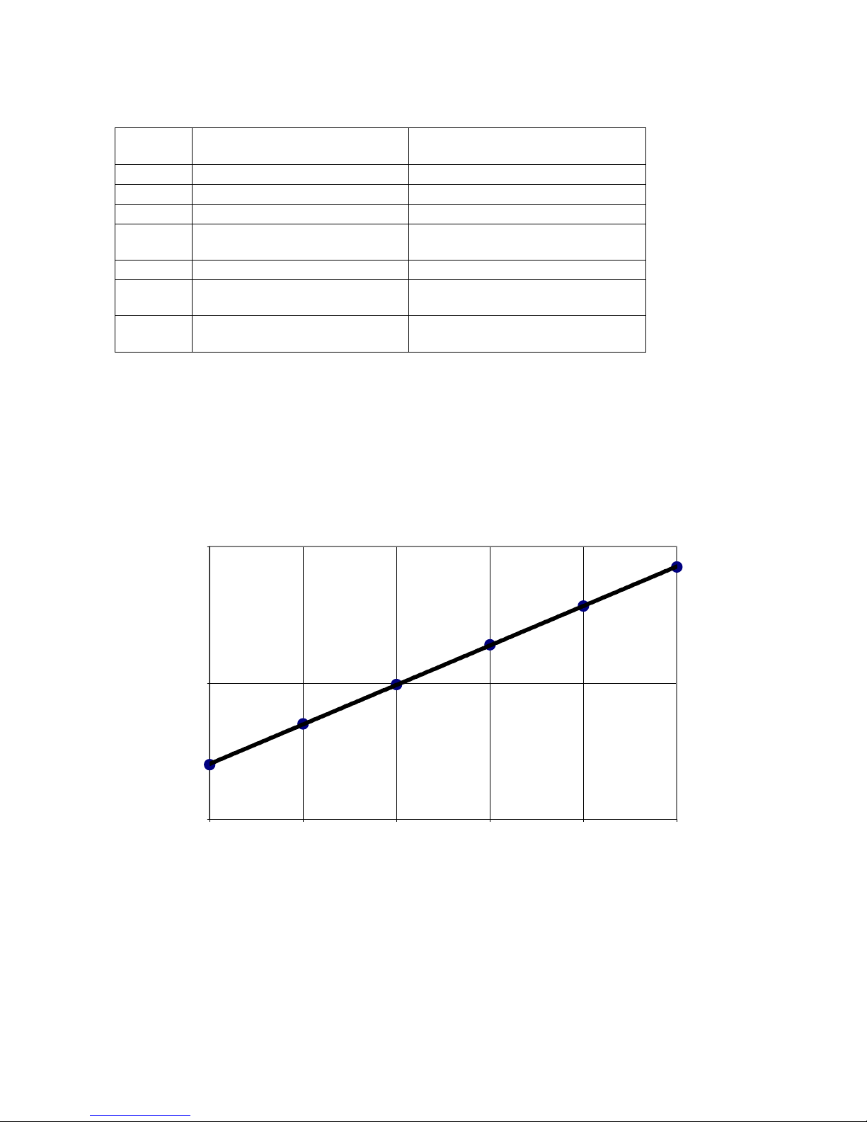
The following commands apply only to intensified cameras:
CMD
Description Range of argument
Code
IGN Intensifier Gain
IPO Intensifier Pulse “ON” Duration
IPD Intensifier Pulse Delay
IMD
Intensifier mode (see below) IOF, ION, PON, SON, PEX
00 ≤ two digit hex value ≤ FF
000 ≤ three digit hex value ≤ FFF
00 ≤ two digit hex value ≤ FF
XYZ
IMD IOF Turn off intensifier See below
IMD ION Turn on intensifier in Gain
See below
mode
IMD
PON
Turn on intensifier in Pulse
mode
uses IPO & IPD; see below
9.4.1 Intensifier Control
The luminous gain of Intensifier tube is controlled in a log-linear fashion via the serial port (IGN
parameter). The intensifier may also be gated to provide duty-cycle control of its "on" time--the
gating is internally derived but controlled via the serial port (IPO and IPD parameters) in several
different modes (set by the IMD parameter).
Intensicam
1.E+05
70795
36728
19055
1.E+04
Luminous Gain
5012
2512
1.E+03
0 51 102 153 204 255
9772
IGN Argument
Figure 9.4-1: Luminous Gain versus IGN Argument
9.4.2 Notes on Intensifier Operation
CAUTION: Do NOT point the intensifier at bright lights or permanent damage to the intensifier
tube may result.
57
Page 64
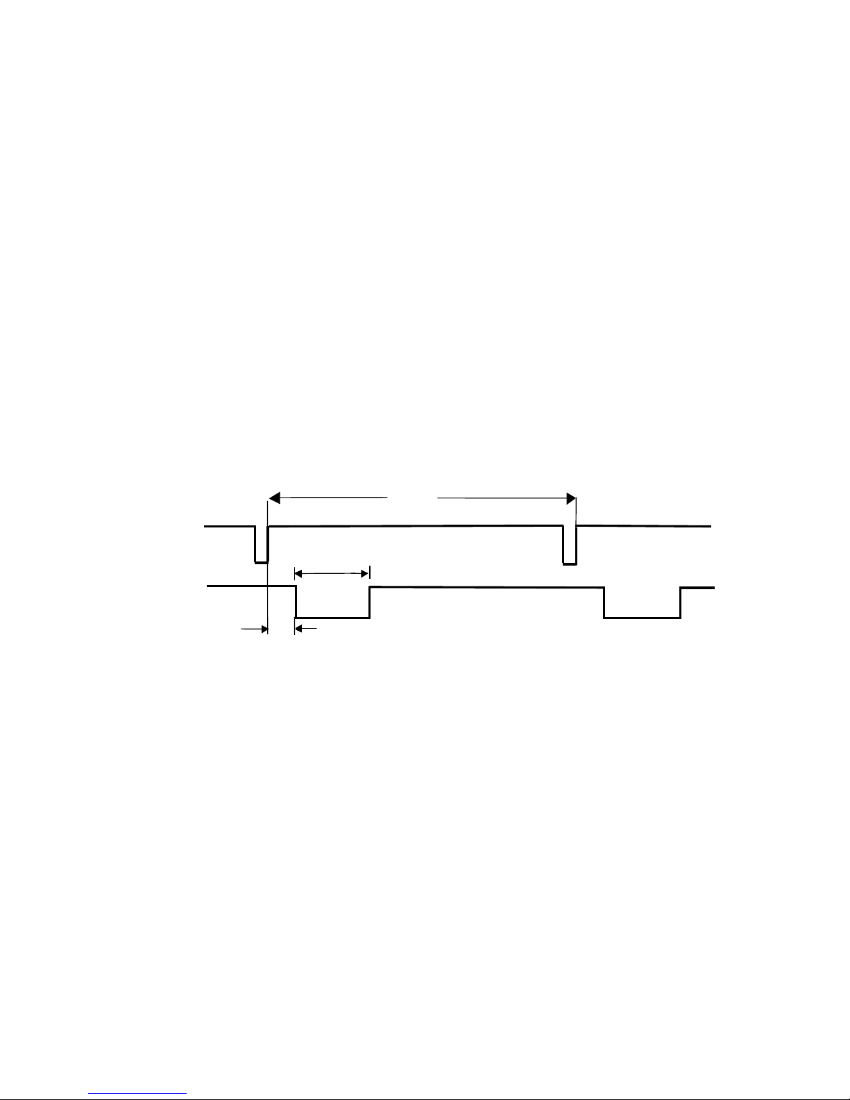
• The INT_PULSE (which is a camera-internal signal) follows negative logic, i.e. the Intensifier
is "off" when this pulse is HIGH; the Intensifier is "on" when this pulse is LOW. This pulse is
used under s/ware control to protect the Intensifier against “photon overload”.
• The pwr on default status of the INT_PULSE is HIGH. This will cut off all light to the camera
(protecting the Intensifier, since it is quite likely that a user may power up the camera before
connecting the cable required to view an image and may accidentally cause damage to the
Intensifier by pointing to a bright source of light for indefinite periods of time). Software will
have to be enabled to turn on the intensifier, by using the IMD [ION,PON,SON] command (see
below). Some apps (e.g. CView) will do this on "connect"; others will follow a more elaborate
process, requiring the user to "enable" the intensifier.
• Command "IMD ION": sets the INT_PULSE to be always LOW; this will set the Intensifier in
the ON state, allowing its gain to be adjusted using the IGN command.
• Command "IMD IOF": sets the INT_PULSE to be always HIGH; this will turn OFF the
Intensifier.
• Command "IMD PON": Sets the Intensifier in the pulse mode; toggling the signal INT_PULSE
once per frame, with a delay IPD (from the falling edge of ENF) and duration IPO.
1/10 sec
EN_FRAME
Intensifier
gating pulse
IPO
IPD
INTENSIFIER
ON (Low)
INTENSIFIER OFF (High)
• IPO: This parameter defines the “ON” or “LOW” time of the Intensifier Pulse in either the
PON(Long) or SON(Short) pulse mode. Depending on the IMD setting (i.e. IMD SON or IMD
PON) the range and the increment of the “ON” time is different. In the PON mode, it is from
25µs to 82.5ms, with 25µs increments .. requiring a three digit hex argument ranging from
001(25µs) to CDA (82.5ms). In the SON mode, it is from 50ns to 204.8µs, with 50ns
increments .. requiring a three digit hex argument ranging from 001(50ns) to FFF (204.8µs).
• IPD: range is from 50ns to 10us, with 50ns increments .. requiring a two digit hex argument
from 00(0ns) to FE(10us) in 50ns increments. Note: FF is not valid.
• Application software developers are advised to send out the IMD IOF command before exiting
(or disconnecting) the app. program, to protect the Intensifier at times when it isn't being used
to make an image.
• Applications may be developed to add "Auto" features, such as AutoBrite (CView
terminology) in which the application software attempts to “find” the correct settings of
Intensifier Gain, Intensifier Pulse “ON” time, and camera gain in order to display a “perfect”
58
Page 65

image. Note: a perfect image may be defined in terms of its peak value, average value or in
terms of its histogram. Also some applications may develop an AutoShut feature (which will
quickly shut off the intensifier under over-bright conditions, then try to make an image with
short/long pulses or Intensifier Gain, depending on the scene illumination.
• IMD SON (Intensifier mode: short Pulse) IMD SON will issue pulses from (50ns, 100ns,
150ns .. 204.8us) depending on IPO parameter (same three digit Hex from 001 to FFF, but now
with a 50ns increment)
• IMD PEX (Intensifier mode: External Pulse), which will tri-state the camera-internal
INT_PULSE pulse (which will float to the “HIGH” level, protecting the Intensifier), allowing
the user to drive the Intensifier gate. IPO and IPD values are ignored. In the next rev of the
camera design, an “auxiliary connector” will be provided which would allow the user to feed
the pulse from an external source.
9.4.3 Notes on Wheel Commands
The following commands apply only to DVC-1412 cameras that are equipped with a multi-spectral
filter wheel; cameras that are not equipped with a wheel will respond to these commands with an
error message.
CMD
Description Range of argument
Code
CWP Color Wheel Position {0,1,2,3,4}
CWT Color Wheel Step Time
00 ≤ two digit hex value ≤ FF
CWS Color Wheel Status Query None
NOTE: In the following description, Red, Green, Blue,Clear/IRFilter represent the "standard"
version of the filter set. In many software applications that are written for RGB color, it may be
sufficient to identify the positions as Clear/IR, Red, Green, Blue. However, the unique design of
the camera allows users to change the filters in multi-spectral applications. Therefore, a more
"generic" software design will call them Position 1,2,3,4 .. and allow users to change the labels
from {Clear/IR, Red, Green, Blue} to something that is relevant their application, like {200nm,
300nm, 400nm, 500nm}.
CWP x[cr] FILTER WHEEL POSITION (HEX 0 - 4)
x = 0 = go to index position (position 3)
x = 1 = go to position 1 (Green)
x = 2 = go to position 2 (Blue)
x = 3 = go to position 3 (Clear/IRFilter)
x = 4 = go to position 4 (Red)
The power-on-default is "CWP 0" which sets up the camera in the Clear/IRFilter position; so the
camera acts just like a DVC-1412 monochrome.
CWT xx[cr] FILTER WHEEL STEP TIME (HEX 01 - 7F)
xx = 0.1 to 12.7 millisecond step time
CWS[cr] FILTER WHEEL STATUS (HEX 0 - 7)
x = *bbb
| | |
| | +------- busy stepping
| + -------- step error
59
Page 66

+ - -------- index error
N
N
N
N
N
N
N
9.5 COMMAND SUMMARY
CMD
code
Description
Range of arguments (all other
arguments will result in an error
msg.)
MDE Mode See table
GAI Gain control (0-to-3VDC)
OFS Offset control (0-to-3VDC)
00 ≤ two digit hex value ≤ 9A
00 ≤ two digit hex value ≤ 9A
BIN Binning mode 11, 21, 22, 44, 88
SLW Slow scan mode 01, 02, 04, 08
Exposure in hi-spd shutter
modes
EXP
Exposure in NFR mode
Exposure in ULT mode
000 ≤ three digit hex value ≤ 414
000 ≤ three digit hex value ≤ 7FF
000 ≤ three digit hex value ≤ 7FF
Low duration of VRST_INT;
50ms to 10sec in 50ms
TIL
01 ≤ two digit hex value ≤ C8
increments
High duration of VRST_INT;
TIH
50ms to 10sec in 50ms
01 ≤ two digit hex value ≤ C8
increments
Hardware reset, 100µsec low
HRT
on VRST_INT
Software reset to default
RST
values
VER Version request
o arguments
o arguments
o arguments
INT
IMD
Intensifier commands
IPO
o arguments (see Intensifier
Commands section)
IPD
CWP
Mulitspectral wheel
CWT
commands
CWS
0,1,2,3,4,
0 ≤ two digit hex value ≤ 7F
o argument
ALL Modify all camera parameters TBD
CAM Camera Type Query
o arguments
STA Status request
o arguments
60
Page 67
10 INFORMATION AND SUPPORT RESOURCES
You can obtain product information at http://www.dvcco.com
For tech support, please contact DVC at (512)-301-9564 or e-mail [email protected]
Our mailing address is the following:
DVC Company
10200 Highway 290 West
Austin, TX 78736
Our address in Europe is the following:
DVC Europe
12, Kingswood Court
Maidenhead, Berks SL6 1DD, England
Phone: +44-1628 625342; Fax: +44-1628 625485
Please obtain the most current information from DVC’s website at http://www.dvcco.com
61
Page 68
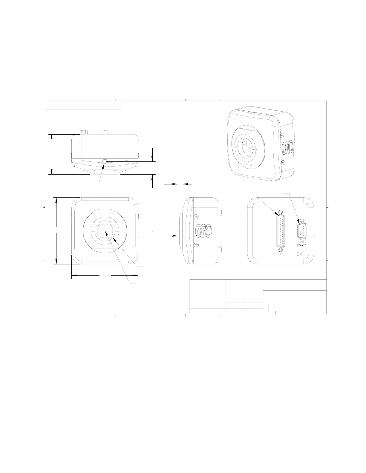
11 APPENDIX
ABC
D
11.1 APPENDIX A: MECHANICAL DIMENSIONS DIAGRAM
TH E I NF ORMATION C ONTAINED IN THIS DRAWING IS THE SOLE
P RO P ER TY OF DV C Co. A NY REPR ODUCTI ON IN PAR T OR WH OLE
W IT HO UT THE WRITTEN PERM ISSION OF DV C Co. IS PR OHIBI TED.
D
(no mi nal )
1.96
C
1/ 4 x 20 Thr ead Mo unt
(top and bottom)
3.25
B
A
Not es:
3.25
(nom in al)
.63
0.12
0.69
To Fo cal Pl ane
1" x 32 tpi
C le ns m ount
Optical C enter
5678
4
Adj usta ble
.25
UN L ESS O THERWI SE SPECI FIED
DI MENSIONS ARE IN INCHES
TO LERANCES ARE:
FRACTIONS DEC IMALS ANGLES
.XX +/- .01
.XXX +/- .005
MAT E R I A L
FI N I S H
3
DB44 I/O
Connector
DO NOT SCALE DRAWI NG
APPROV ALS
DRAWN
CHECKED
DB9 Mal e
Power Connector
DVC Company
10200 Hw y 290 West, Austin, TX 78 736
DAT E
1310 a nd 1312 Camera Assy
LVDS w/DB44 Connector
DWG . N O.
SI Z E
A
CAD FILE:
SC A L E
2345678
12
SHEET 1 OF 1
1
Figure 11.1-1: 1412 with LVDS connector
62
Page 69
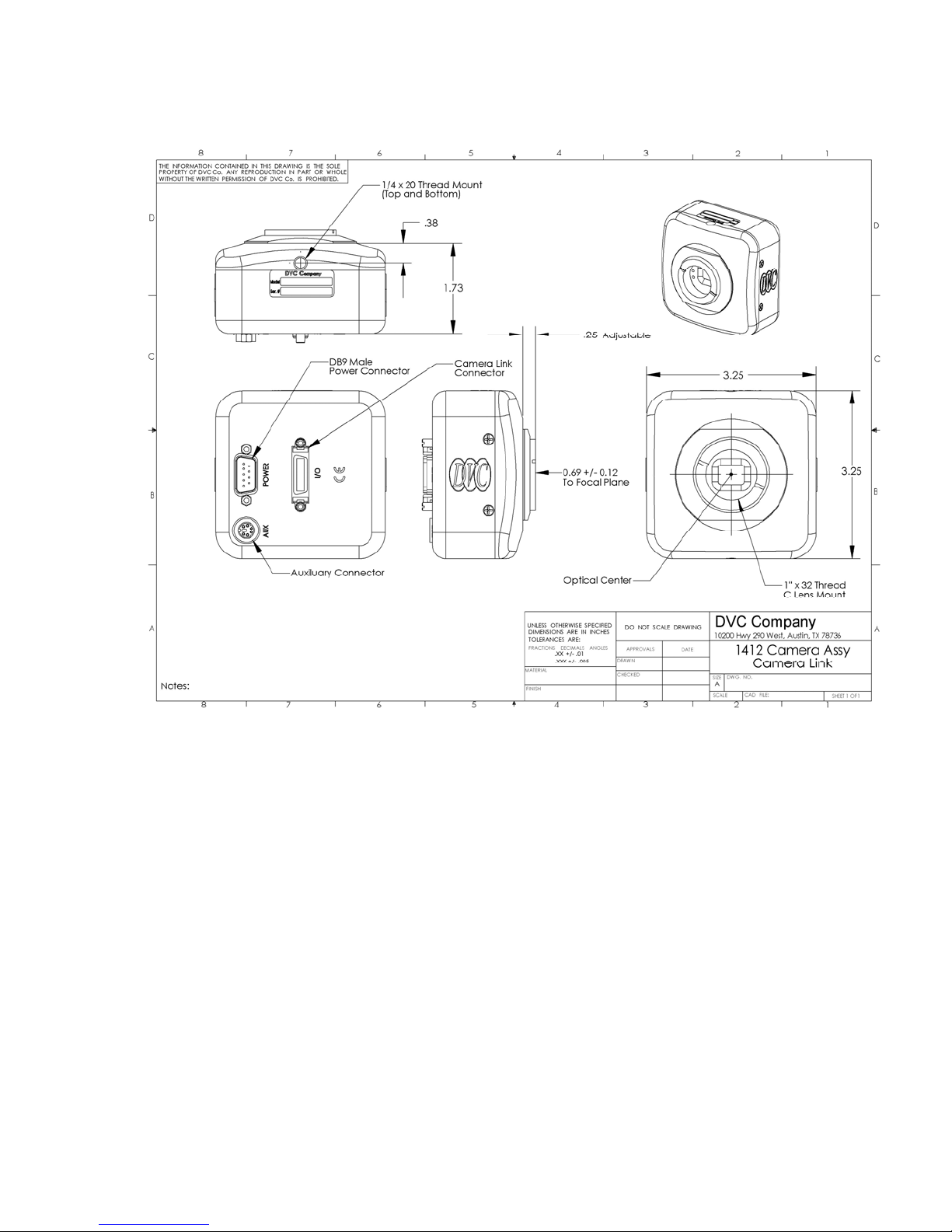
Figure 11.1-2: 1412 with CameraLink connector
63
Page 70
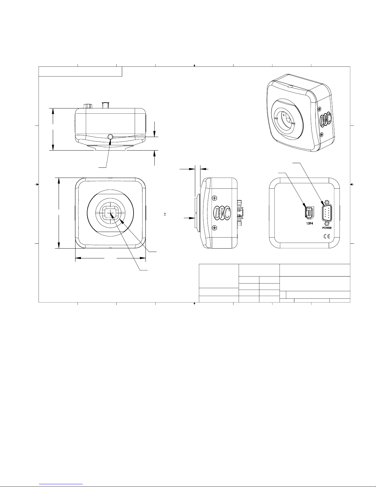
8
THE INFORMATION CONTAINED IN THI S DRAWING IS THE SOLE
PROPERTY OF DVC Co. ANY REPRODUCTION IN PART OR WHOLE
WITHOUT THE WRITTEN PERMISSION OF DVC Co. IS PROHIBITED.
D
(nom in al)
1.96
C
1/4 x 20 Thread Mount
(top and bottom)
B
3.26
(nom in al)
.64
0.69 0.12
To Focal Plane
567
4
3
12
D
C
DB9 Male
Power Connector
Adjustable
.25
IEEE 1394
Connector
B
A
Notes:
1" x 32 thread
3.26
8
7
C lens mount
Optical Center
UNLESS OTHERWISE SPECIFIED
DIMENSIONS ARE IN INCHES
TOLERA NCES ARE :
FRACTIONS DECIMALS ANGLES
.XX +/- .01
.XXX +/- .005
MATERIAL
FINIS H
456
DO NOT SCALE DRAWING
APP ROV AL S
DRAWN
CHECKED
3
DVC Company
10200 Hwy 290 West, Austin, TX 78736
DATE
1310 and 1312 Camera Assy
IEEE 1394
DWG. NO.
SIZE
A
SCALE
CAD FILE:
2
SHEET 1 OF 1
1
A
Figure 11.1-3: 1412 Camera with 1394 Connector
64
Page 71
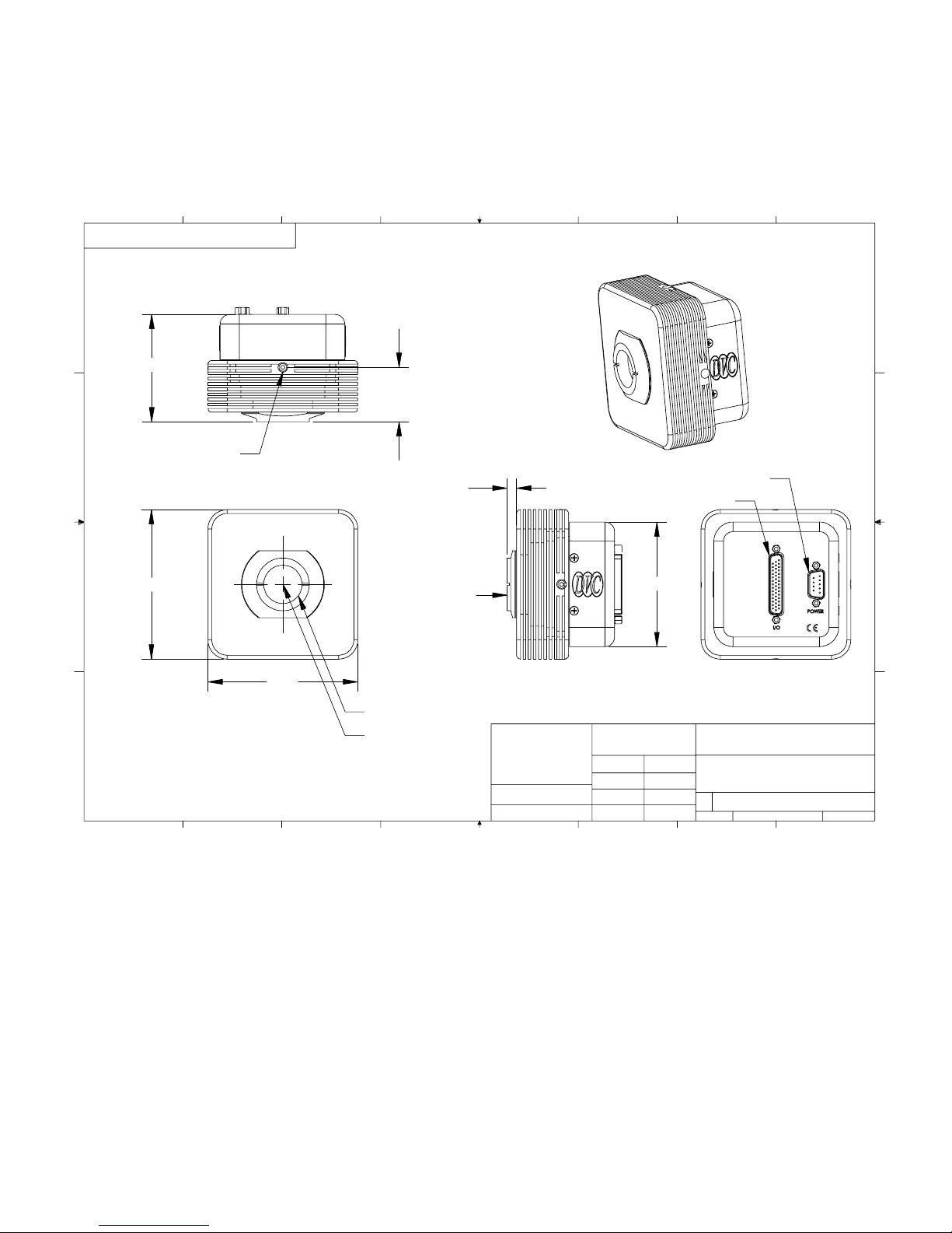
8
THE INFORMATION CONTAINED IN THIS DRAWING I S THE SOLE
PROPERTY OF DVC Co. ANY REPRODUCTION I N PART OR WHOLE
WITHOUT THE WRITT EN PERMISS ION OF DVC Co. IS PROHI BITED.
D
(no min al)
2.80
C
B
1/4 x 20 Th read Mount
(4 sides)
3.90
567
(no min al)
1.42
0.69 +0.12/-0.04
To Focal Plane
4
(no min al)
.25
3
DB9 Male
Power Connector
DB44 I/O
Connector
3.25
12
D
C
B
3.90
1" x 32 thread
C Lens Mount
A
Notes:
Optical Center
8
7
UNLESS OTHERWISE SPECIFIED
DIMENSIONS ARE IN INCHES
TOLERANCES ARE:
FRACTIONS DECIMALS ANGLES
.XX +/- .01
.XXX +/- .005
MATERIAL
FINIS H
456
DO NOT SCALE DRAWING
APP ROV AL S
DRAWN
CHECKED
3
DVC Company
10200 Hwy 290 West, Austin, TX 78736
DATE
TE Cooler Camera Assy.
DWG. NO.
SIZE
A
SCALE
CAD FILE:
2
SHEET 1 OF 1
1
A
Figure 11.1-4: 1412 TE Cooler Camera (LVDS model shown)
65
Page 72
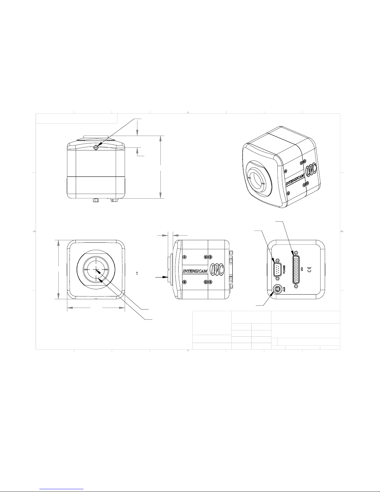
8
THE INFORMATION CONTAINED IN THIS DRAWING IS THE SOLE
PROPERTY OF DVC Co. ANY REPRODUCT ION IN PART OR WH OLE
WITHOUT THE WRITTEN PERMISSION OF DVC Co. IS PROHIBITED.
D
C
B
3.25
1/4 x 20 Thread Mount
.66
.28
0.69 0.12
To Focal Plane
3.46
567
4
DB9 Male
Power Connector
3
DB44 Female
LVDS Connector
12
D
C
B
A
Notes:
3.25
8
7
Optical Center
1" x 32 tpi
C lens mount
UNLESS OTHERWISE SPECIFIED
DIMENSI ONS ARE IN INCHES
TOLERANCES ARE :
FRACTIONS DECIM ALS ANGLES
MATERIAL
FINIS H
Auxiliary Connector
.XX +/- .01
.XXX +/- .005
456
DO NOT SCALE DRAWING
APPROVALS
DRAWN
BVP
CHECKED
3
DVC Company
10200 Hwy 290 West, Austin, TX 78736
DATE
SIZE
A
SCALE
DWG. NO .
CAD FILE:
2
Intensicam Assy
10-0065-01
SHEET 1 OF 1
1
A
Figure 11.1-5: Intensicam-1412 Image Intensifier Camera (LVDS shown)
66
Page 73
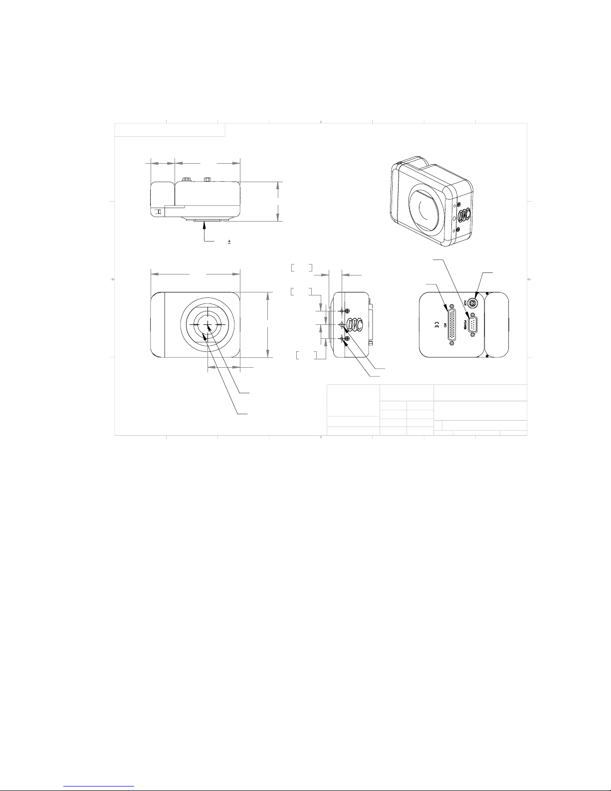
8
THE INFORMATION CONTAINED IN THIS DRAWING IS THE SOLE
PROPERTY OF DVC Co. ANY REPR ODUCTION IN P ART OR WHOLE
WITHOUT THE W RITTEN PERMIS SION OF DVC Co. I S PROHIBIT ED.
D
1.22
C
4.47
B
A
Notes:
8
7
3.25
0.69 .062
To Focal Plane
1.99
3.26
1.625
Optical
Center
1" x 32 tp i
C lens mount
567
16.17
.636
17.48
.69
17.48
.69
4
UNLESS OTHERWISE SPECIFIED
DIMENSIONS ARE IN INCHES
TOLERANCES ARE:
FRACTIO NS DEC IMALS ANGLES
.XX +/- .01
.XXX +/- .005
MATERIA L
FINISH
3
DB9 Male
Power Connector
DB44 Female
LVDS Connector
1/4 x 20 Thread Mount
M4 Thread Mount
DO NOT SCALE DRAWING
APPROVALS
DRAWN
BVP
CHECKED
DATE
3456
12
Auxiliary
Connector
DVC Company
10200 Hw y 290 West, Austi n, TX 78736
Filter W heel Camera
DWG. NO.
SIZE
A
SCALE
CAD FILE :
2
10-0144-01
1
SHEET 1 OF 1
D
C
B
A
Figure 11.1-6: 1412-Multispectral Wheel Non-Cooled Camera (LVDS shown)
67
Page 74
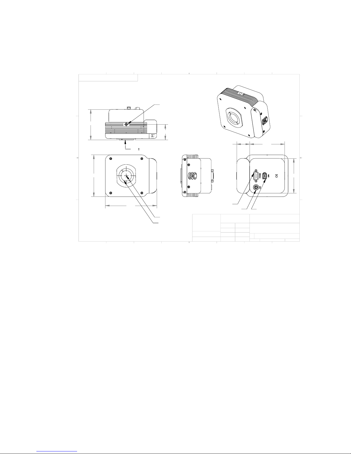
8
THE INFORMATION CONTAINED IN THIS DRAWING IS THE SOLE
PROPERTY OF DVC Co. ANY REP RODUCTIO N IN PART OR WHOLE
WITHOUT T HE WRITTEN PERMIS SION O F DVC Co. IS PR OHIBITED.
567
4
3
12
D
C
A
B
Notes :
2.85
3.90
8
7
0.69 0.062
To Fo cal Pla ne
4.79
1/4 x 20 Thread Mount
1.46
Optica l Center
1" x 32 tpi
C lens mo unt
DB9 Male
Power Connector
UNLESS OTHERWISE SPECIFIED
DIMENSIONS ARE IN INCHES
TOLERANCES AR E:
FRACTIONS DECIMALS ANGLES
.XX +/- .01
.XXX +/- .005
MATERIAL
FINISH
456
Auxiliary Connector
DO NOT SC ALE DRAWING
APPROVALS
DRAWN
BVP
CHECKED
3
3.251.21
Firewire Connector
DVC Company
10200 Hwy 290 West, Austin, TX 78736
DATE
Cooled Filter Camera
DWG. NO.
SIZE
SCALE
A
CAD FILE:
2
10-0143-01
1
3.25
SHEET 1 O F 1
D
C
B
A
Figure 11.1-7: 1412-Multispectral Wheel Cooled Camera (FireWire shown)
68
Page 75

11.2 APPENDIX B: CABLE DRAWINGS
Figure 11.2-1: DVC-1412-to-pixeLNYX cable
69
Page 76

Figure 11.2-2: CameraLink cable
70
Page 77

Figure 11.2-3: DVC-1412-MV1500 cable
71
Page 78

Figure 11.2-4: DVC-1412-to-Matrox Meteor II DIG cable (LVDS)
72
Page 79
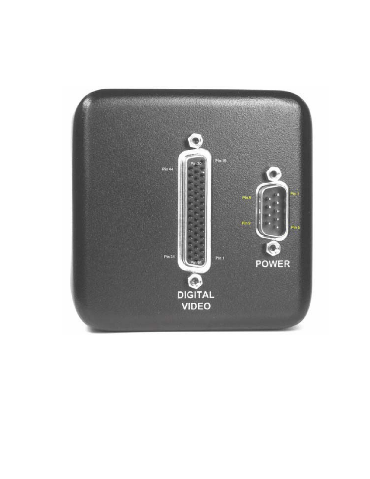
11.3 APPENDIX C: DVC-1412 CAMERA CONNECTORS
Figure 11.3-1: Camera rear view showing connector pin numbers (LVDS connections shown)
73
Page 80
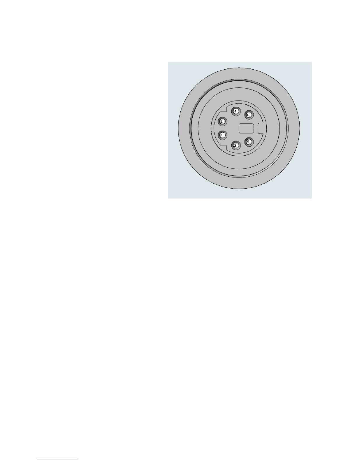
11.3.1 Auxiliary Connector
11.3.1.1 Pin Descriptions:
pin# signal
------------------
1 HD (Output)
2 INPUT1 (Output) (not used on FireWire cameras)
3 VRST_INT (Input)
4 GND
5 EN_FRAME (Output)
6 STROBE/INT-PULSE (Output)
11.3.1.2 Signal Descriptions:
11.3.1.2.1 Pin 1, HD
HD refers to Horizontal Drive and is a TTL output signal. It is active high and is
asserted during the valid pixel period on each line (it is also asserted during the
interframe period as illustrated in the diagram below). It returns low during the
inter-line period between each line. Also referred to in the industry as
“Enable_Line” or “ENL”
11.3.1.2.2 Pin 2, INPUT1
INPUT1 is only used on LVDS and CameraLink cameras and is a camera trigger
signal that is supplied to the camera via the LVDS and CameraLink interfaces. It is
brought back out of the camera on the AUX connector on pin 2 for use by other
equipment. Since the FireWire interface has no INPUT1 input, this signal is
unused on FireWire cameras. Refer to section 7.2.3 in the 1412A technical manual.
74
Page 81
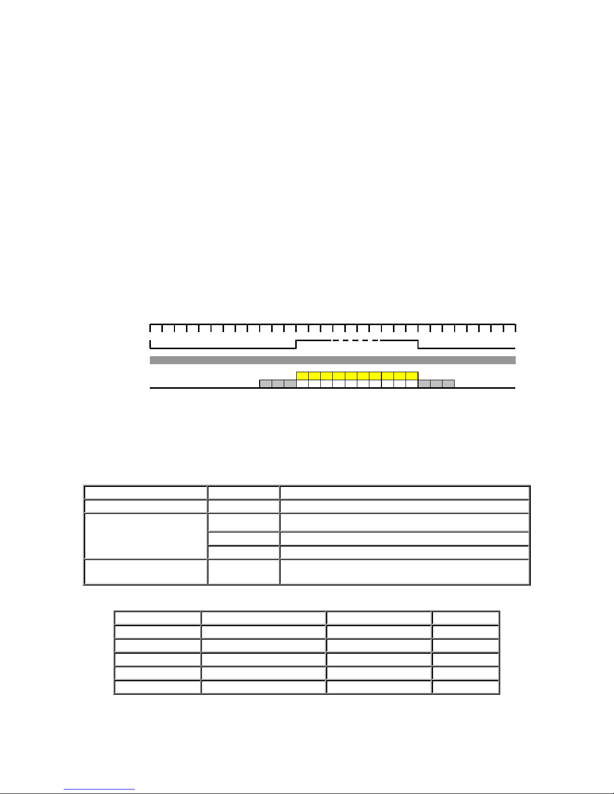
11.3.1.2.3 Pin 3, VRST_INT
VRST_INT is a TTL input used to trigger exposures in certain modes. Refer to
Section 7 in this technical manual for descriptions of how VRST_INT affects the
camera in triggerable modes. VRST_INT allows the FireWire cameras triggering
that is identical to INPUT1, as described in this manual.
11.3.1.2.4 Pin 4, GND
Common electrical ground for the camera.
11.3.1.2.5 Pin 5, EN_FRAME
EN_FRAME refers to Enable Frame and is a TTL output that is high during active
readout lines. It returns low between frames (See diagram below).
11.3.1.2.6 Pin 6, STROBE/INT-PULSE
STROBE/INT-PULSE is a TTL output that is high during the actual sensor
exposure time when electronic shuttering is invoked. It is only valid in HDO or
HNL modes, when electronic shuttering is active, and it is typically used to
synchronize a stroboscopic flash with the camera.
HD or
EnableLine
En_Frame
Pixel Clock
CCD Output
BLK BLK BLK 1 2 .... .... .... .... … … … 1030 BLK BLK
V I D E O
BLK
Figure 11.3-2: Diagram illustrating HD and EN_FRAME signals relative to the master pixel clock and the CCD output
11.3.2 Connector Overview
Connector Name On Camera Interface Cable
Power Supply Connector DB9M DB9F; e.g. AMP P/N: 205203-1 with 66504-3 pins
DB-44F DB44M; e.g. AMP P/N: 748366-1 with 748333-2 pins
Digital Video Connector MDR-26 Standard CameraLink
6 pin 1394A Standard Firewire
Auxiliary Connector
Pin No. Signal Name Signal Name Pin No.
6 GND +5VOLTS DC 1
7 STROBE (TTL) RESERVED 2
8 GND -15VOLTS DC 3
9 HD (TTL) VD (TTL) 4
Mini-Din-6
receptacle
Table 11.3-1: Camera connector information
Table 11.3-2: Power supply connector pinout
Mini-Din Male; e.g. AMP P/N 750329-2
+15VOLTS DC 5
75
Page 82

Pin no. Signal Pin no. Signal Pin no. Signal
16 PIXCLK-
1 PIXCLK+ 31 ENL+
17 GND
2 GND 32 ENL-
18 ENF-
3 ENF+ 33 Not used
19 MSB-
4 MSB+ 34 INPUT1+
20 (MSB-1)-
5 (MSB-1)+ 35 INPUT1-
21 (MSB-2)-
6 (MSB-2)+ 36 R1 IN
22 (MSB-3)-
7 (MSB-3)+ 37 T1 OUT
23 (MSB-4)-
8 (MSB-4)+ 38 COM GND
24 (MSB-5)-
9 (MSB-5)+ 39 VRST_INT
25 (MSB-6)-
10 (MSB-6)+ 40 Reserved
26 (MSB-7)-
11 (MSB-7)+ 41 GND
27 (MSB-8)-
12 (MSB-8)+ 42 Reserved
28 (MSB-9)-
13 (MSB-9)+ 43 GND
29 (MSB-10)-
14 (MSB-10)+ 44 Reserved
30 (MSB-11)-
15 (MSB-11)+
Table 11.3-3: LVDS Digital video connector pinout
76
Page 83

12 WARRANTY AND AFTER-SALES SERVICE
DVC Company warrants equipment manufactured to be free from defects of material and
workmanship. Any part or parts will be repaired or replaced when proven by DVC examination to
have been defective within two years from the date of shipment to the original purchaser. Any
warranty repairs will be performed at the factory or as otherwise authorized by DVC, in writing.
Transportation charges to DVC shall be pre-paid by purchaser.
This warranty does not extend to DVC manufactured equipment subjected to misuse, accident,
neglect or improper application. Nor does the warranty extend to DVC manufactured equipment
that is repaired or altered by anyone other than DVC or those authorized by DVC, in writing.
Products manufactured by other companies, but re-sold by DVC such as lenses, optical and electrooptical assemblies, power supplies, cables, image processor boards and software are warranted by
the original manufacturer.
This warranty is in lieu of all other warranties expressed or implied. DVC shall not be liable for
any collateral or consequential damages.
A Return Material Authorization (RMA) Number must be obtained from DVC prior to returning
any item for warranty repair or replacement.
77
Page 84

13 COPYRIGHT INFORMATION
Copyright © 2002 DVC Company. All rights reserved.
Copyright on this document is owned by DVC Company, 10200 Highway 290 West, Austin,
Texas 78736
The information contained in this document is proprietary to DVC Company. Information in this
document may be used for non-commercial, personal and educational information purposes only,
and may be viewed, copied, printed and distributed only in accordance with these terms and
conditions of use. This information may not be copied nor duplicated in any form, in whole or in
part, for use for profit or another business. All printouts, copies or reproductions of all or any part
of the information contained in this document must include all patent, copyright and/or trademark
notices originally included with the information. User obtains no rights in the information or in any
product, process, technology or trademark which it includes or describes, and is expressly
prohibited from modifying the information or creating derivative works without the express written
consent of DVC Company. DVC models represented in photographs may differ slightly from
products shipped due to continuing product improvements and variations. DVC reserves the right
to make changes to product specifications and documentation at any time without notice. The
information on, or references from, this document are believed to be accurate and reliable,
however, no responsibility is assumed by DVC for its use. DVC reserves the right to change,
modify or correct the information contained in this document at any time without notice. While
DVC has used all reasonable efforts to indicate and to supply information regarding trademarks
used in this publication, the absence of a trademark identifier is not a representation that a
particular mark is not a trademark. All non-DVC products, brand names, company names are
trademarks or registered trademarks of their respective owners, and appear in this document for
reference only.
Disclaimer: The information in this document is provided "as is". DVC expressly disclaims all
representations and warranties of any kind regarding the contents or use of the information including, but not
limited to, express and implied warranties of accuracy, completeness, merchantability, fitness for a particular
use, or non-infringement. In no event will DVC be liable for any direct, indirect, special, incidental or
consequential damages, including lost profits, lost business, or lost data, resulting from the use or reliance
upon the information, whether or not DVC has been advised of the possibility of such damages.
78
 Loading...