


BASLER ACE
QUICK INSTALLATION GUIDE
Rev. 01
Quick installation Guide V1

1 Introduction
The installation procedures in this guide assume that you want to get your camera operational
and begin capturing images as quickly and as simply as possible. Accordingly, this procedure
makes the following assumptions:
That you will be doing a desktop installation of a single ace camera f or testin g purpo ses.
That you will be using a PC equipped with one of the following operating systems:
32 bit Windows 2000 SP4 64 bit Windows XP x64 SP2
32 bit Windows XP SP2/SP3 64 bit Windows Vista x64
32 bit Windows Vista
That you will be connecting the ace camera directly to a single port GigE network card in
the PC and that the PC has only one network card.
That the chipset on the network card in the PC is compatible with the Basler performance
driver included in the pylon package. To see a current list of the compatible chipsets, go
to:
www.baslerweb.com/beitraege/faq_en_74662.html
That you will be using a GigE power injector or a 12 VDC camera power supply obtained
from Basler (or the equivalent) to power the camera.
That you will be installing the Basler pylon software package on your computer and that
pylon software is being installed for the first time. You can download the pylon package
here:
www.baslerweb.com/beitraege/maildownload_formular_en_59126.html
Be sure to download the pylon version that is appropriate for your operating system.
This procedure assumes that you will be installing pylon version 2.2 (the most current
version on the date this document was written). If you install an earlier version, the
camera’s functionality may be limited.
That you will be using the pylon Viewer to set the parameters on your camera and to view
captured images.
1.1 General Preparations
Make sure that the following items are available before starting installation:
A Basler ace camera.
A suitable power supply for the camera.
A Cat 6E or better network cable (two cables if you are using a power injector).
An appropriate lens.
Quick installation Guide V1 DVC 2

2 Installation Procedures
2.1 Installing Basler pylon
If there are any cameras connected to your PC, disconnect them now.
Once you have downloaded the software package, you can install the software by doing the
following:
1. We most strongly recommend that you close all open applications now.
2. Navigate to the location where you downloaded the pylon softw are installation package
and double-click on the installation package file.
3. A Security Warning message may appear. If so, click the Run button.
4. The program will prepare to install and then a Welcome window will open. Click the Next
button.
5. A License Agreement window will open. Accept the agreement and click the Next button.
6. A Customer Information window will open. Enter the appropriate information and click the
Next button.
7. A Destination Folder window will open. In the Destination window:
If you want the software to be installed in the default location, click the Next button.
If you want the software to be installed in a different location, click the Change button,
navigate to the location where you want the software installed, and click the OK
button.
8. A Custom Setup window will open.
Deselect the components that you do not want to inst all:
To deselect an item, click the
the dropdown menu that appears. In the example shown below, we have deselected
the pylon IEEE 1394 Drivers and the pylon Camera Link Driver (the Additional
Runtimes are deselected by default). If you will only be using GigE cameras with your
PC, we strongly suggest that you deselect the IEEE 1394 Drivers and the Camera
Link Driver.
(Individual components can easily be installed at a later time.)
button next to the item and select the red X from
Quick installation Guide V1 DVC 3

Click the Next button.
9. A Ready to Install the Program window will open. Click the Install button.
10. When the installation process is complete, a Completed window will open.
Click the Finish button.
11. An Installer Information window may open informing you about the need to restart the
computer. If you see this message, restart the computer now.
12. Note that the installation program has added a shortcut to the desktop for the Pylon
Viewer and for the Pylon IP Configuration Tool.
13. To see all of the installed software components:
Click Start > All Programs > Basler Vision Technologies > Pylon x.x.
2.2 Disabling the Windows Firewall
Basler pylon software requires that the Windows firewall to be disabled on all interfaces where
cameras are connected. To disable the Windows firewall via the traditional control panel:
1. Open the Windows Firewall window:
Depending on your operating system, use one of the following procedures:
Windows XP:
Start > Control Panel > Security Center > Windows Firewall
Windows Vista:
Start > Control Panel > Security Center > Change Settings > Windows Firewall
Quick installation Guide V1 DVC 4
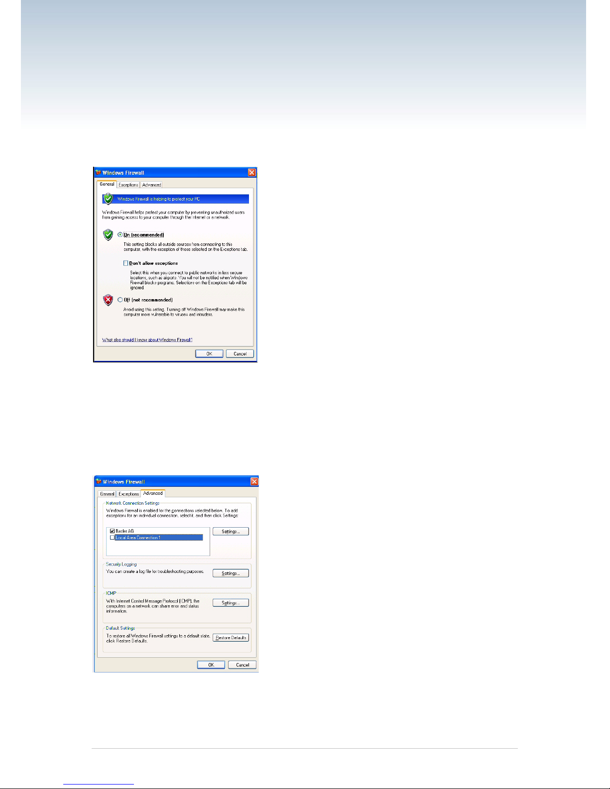
On the General tab of the Windows Firewall window, the On (Recommended) option button
can be selected. Disabling of the Firewall is done on the Advanced tab.
2. On the Advanced tab:
In the Network Connection Settings group:
Deselect the check box for the network adapter where camera will be attached (see
Local Area Connection 1 in the followi n g example).
Leave your company’s network firewall enabled (see Basler AG in the following
example).
3. Click OK.
Quick installation Guide V1 DVC 5

2.3 Installing the Hardware
If you are using a 12 VDC camera power supply:
Connect one end of a network cable to the network connector on the camera, and
connect the other end of the cable to the network connector on the GigE network ada pt er
in your PC.
Connect one end of the AC cord for the power supply to the power supply’s body and the
other end to an AC wall outlet.
Connect the 6-pin connector on the output of the power supply to the 6-pin connector on
the camera.
Your camera will power up and will acquire an IP address from the PC (see the note
below).
Go on to Section 2.4
If you are using a GigE PoE power injector:
Connect one end of a network cable to the network connector on the power injector
labeled "Data In", and connect the other end of the cable to the network connector on the
GigE network adapter in your PC.
b. Connect one end of the AC cord for the power injector to the injector’s body and the
other end to an AC wall outlet.
c. Connect one end of a network cable to the network connector on the power injector
labeled "PoE Out", and connect the other end of the cable to the network connect or on
the camera.
d. Your camera will power up and will acquire an IP address from the PC (see the note
below).
Go on to Section 2.4.
Quick installation Guide V1 DVC 6

2.4 Changing a Camera’s IP Configuration
An application called the IP Configuration Tool is included as part of the pylon driver installation
package. The IP Configuration Tool lets you make changes to the IP configuration of your
camera. To start the IP Configuration Tool:
Double click the pylon IP Configuration Tool icon on your desktop
Or click Start, click All Programs, click Basler Vision Technologies, click Pylon x.x,
click Pylon IP Configuration Tool.
The tool will start and an IP Configurator window wil l open as shown below.
When the tool starts, it scans for cameras attached to the PC’s network adapters. All cameras
detected will be listed by model name and serial number in a box on the left side of the IP
Configurator window. To select a camera to work with, click on its name in the list.
When you select a camera, the tool will display IP configuration and other basic information for
the camera in various boxes:
The Device Information box will display the Vendor’s name, the Serial Number, the
MAC address, and the Device User ID (if one has been assigned) for the selected
camera.
When the tool is in edit mode, the Current IP Address box will display the current IP
Address, Subnet Mask, and Default Gateway for the selected camera. (When the tool is
in list mode, this information is not available and N/A is displayed.)
Quick installation Guide V1 DVC 7

If the selected camera has a persistent (fixed) IP Address assigned to it, the Persistent
IP Address box will display the current persistent IP Address, Subnet Mask, and Default
Gateway.
The Connected to box will display the IP Address for the network adapter to which the
selected camera is connected.
The IP Configuration Protocol box will display the current IP configuration of the
selected camera.
If you would like to make sure that all of the displayed information is current, click the Refresh
button. The tool will rescan the cameras and update the displayed information. The IP
Configuration Tool has two modes, List Mode and Edit mode:
When the tool is first opened it is in List mode. In list mode, the tool can display a list of
detected cameras, can display information about the camera selected in the list, and will
let you assign a temporary IP address to the selected camera. When in list mode, the tool
does not have a control channel open to any of the detected cameras. In list mode, the
tool communicates with the cameras at a very low level.
When the Change Configurati on button is pressed, the tool will enter Edit mode. In edit
mode, the tool will open a control channel to the selected camera. Once the control
channel is open, the tool can make changes to things such as the selected camera’s
persistent IP address or Device User ID. Clicking the Write Configuration button takes
the tool out of Edit mode and places it in List mode.
Assigning a Temporary IP Adress to a Camera
You can use the IP Configuration Tool to assign a temporary IP address to a selected camera.
Once a temporary IP address has been assigned to a camera, the camera will retain and use the
temporary IP address until you do one of the following:
Perform a camera reset or switch the camera off and back on.
Assign a different temporary IP address to the camera.
Use the tool to make permanent changes the camera’s IP configur ati o n.
A situation where you might want to assign a temporary IP address to a camera would be, for
example, if you temporarily moved the camera from the PC where it is normally connected to
another PC that is in a different subnet.
To assign a temporary IP address to a camera:
1. Click on the camera’s name in the list at the left side of the IP Configurator window.
2. Click the Assign Temporary IP Address button.
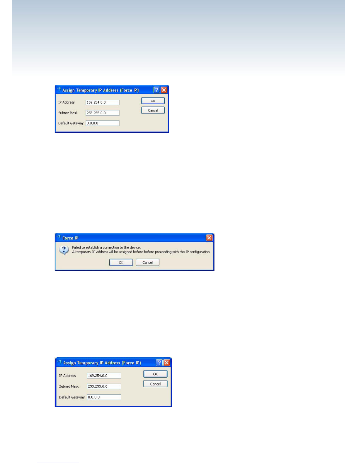
3. An Assign Temporary IP Address (Force IP) window will open as shown below:
Enter your desired IP Address, Subnet mask, and Default Gateway.
(Keep in mind that for the camera to communicate properly with the network adapter
to which it is attached, the camera must be in the same subnet as the adapter and
the camera must have a unique IP address.)
Click the OK button.
The selected camera’s current IP address will immediately be changed and the IP
Configurator window will be updated to reflect the changes.
Quick installation Guide V1 DVC 8
Making Changes to the Camera’s IP Configuration
You can use the IP Configuration Tool to make permanent changes to the ca mer a’s IP
configuration. (Permanent means that the changes will stay in place even when the camera is
reset or switched off and back on.) If you want to change the IP configuration of the camera:
1. Click on the Change Configuration button.
In some cases (such as when the camera’s current IP address is misconfigured), a
Force IP window will appear as shown below. The message in the window will
indicate that you must first assign a temporary IP address. If you see this message,
go to step 2.
If you do not see a message about assigning a temporary IP addr ess, go to step 3.
2. Click the OK button in the Force IP window. An Assign Temporary IP Address (Force
IP) window will open as shown below.
Enter an IP Address, Subnet Mask, and Default Gateway. (If you are using the
camera in a peer-to-peer network, you do not normally need to enter a default
gateway.) (Keep in mind that for the camera to communicate properly with the
network adapter to which it is attached, the camera must be in the same subnet as
the adapter and the camera must have a unique IP address.)
Click the OK button.
The camera’s IP address will be changed and the Assign Temporary IP Address
(Force IP) window will close.
Go on to step 3.
Quick installation Guide V1 DVC 9

3. The IP configurator window will enter edit mode an d will now allow you to enter new IP
values as shown below.
If desired, enter a Device User ID for the camera.
If you want to assign the camera a persistent (fixed) IP address, enter an IP address,
a subnet mask, and a default gateway. Also make sure that the Use Persistent IP
check box is checked. (Before you assign a persistent IP address, you should read
the notes that appear in the note at the end of this procedure.)
If you want the camera to use DHCP address assignment (i.e., to obtain an IP
address from a DHCP server attached to the same network as the camera), make
sure that the Use DHCP check box is checked and that the Use Persistent IP check
box is not checked.
4. When you are finished making changes, click the Write Configuration button. A message
will appear indicating that the camera is restarting its IP configuration cycle as shown
below. When this message disappears the changes to the IP configuration will be in
place and the IP Configurator window will now show the changed settings.
Quick installation Guide V1 DVC 10

2.5 Acquiring Your First Images and
Changing Camera Settings
The easiest way to acquire your first images and to change the camera’s settings is to use the
pylon Viewer software that was installed earlier with the pylon package. In this section we will
show you how to acquire images and how to set the camera so that it automatically adjusts gain
and exposure. We will also show you how to adjust some basic settings that you will want to
work with right away.
To acquire your first images:
1. Put an object within the camera’s field of view and make sure that the object is well
illuminated.
2. Open the lens aperture on your camera "halfway" by choosing an intermediate f-number.
3. Start the pylon Viewer, by clicking the icon on your computer’s desktop. The viewer
window will open as shown below and you should see an entry in the Device tree for your
ace camera.
Menu Bar
Tool Bar
Device Tree
Image Display Area
Quick installation Guide V1 DVC 11

4. Click on your camera’s name in the Device tree to select the camera. A camera Features
pane will open in the viewer as shown below. You will use the selections in the Features
pane to adjust all of the camera’s parameter settings.
Also notice the User Level setting below the Features pane. Choose the Beginner, Expert,
or Guru level to display the basic, intermediate, or advanced camera parameters
respectively. If you don’t have previous experience with Basler digital cameras, we
suggest that you start as a beginner.
5. To get you capturing good quality images quickly. We will turn on the automatic gain and
exposure controls. To turn on the controls:
In the Camera Features Pane, click the + Sign next to the camera name. The tree will
expand and will display a list of parameter groups.
Click the + Sign next to the Analog Controls parameter group. The parameter group
will open.
Use the dropdown list next to the Gain Auto parameter to set the parameter value to
Continuous as shown below.
Scroll down and click the + Sign next to the Acquisition Controls group name. The
parameter group will open.
Use the dropdown list next to the Exposure Auto parameter to set the parameter
value to Continuous.
Quick installation Guide V1 DVC 12

6. Click the icon in the Menu Bar to place the camera into continuous image capture mode.
The images captured by the camera will be displayed in a display window as shown
below.
7. Focus the lens so that you get a good image. Notice that if you vary the light intensity on
the object, the camera will automatically adjust the image quality. This happens because
the auto gain and exposure controls are on continuously.
8. Now you have started capturing images.
Quick installation Guide V1 DVC 13
 Loading...