


TYPE 5320
INSTALLATION, OPERATION AND MAINTENANCE MANUAL
I O M . U K . D V C . 5320. 300 6 15- R E V . B
PAGE 1
TYPE 5320
Mechanical limit switch box

TYPE 5320
INSTALLATION, OPERATION AND MAINTENANCE MANUAL
I O M . U K . D V C . 5320. 300 6 15- R E V . B
PAGE 2
TABLE OF CONTENTS
1. Introduction
3
1.1 Purpose
3
1.2 Safety notice
3
2. Product identification
4
2.1 Marking
4
2.2 Initial inspection
4
2.3 Storage
4
3. General information
5
3.1 Type 5320 standard technical data
5
3.2 Type 5320 optional technical data
5
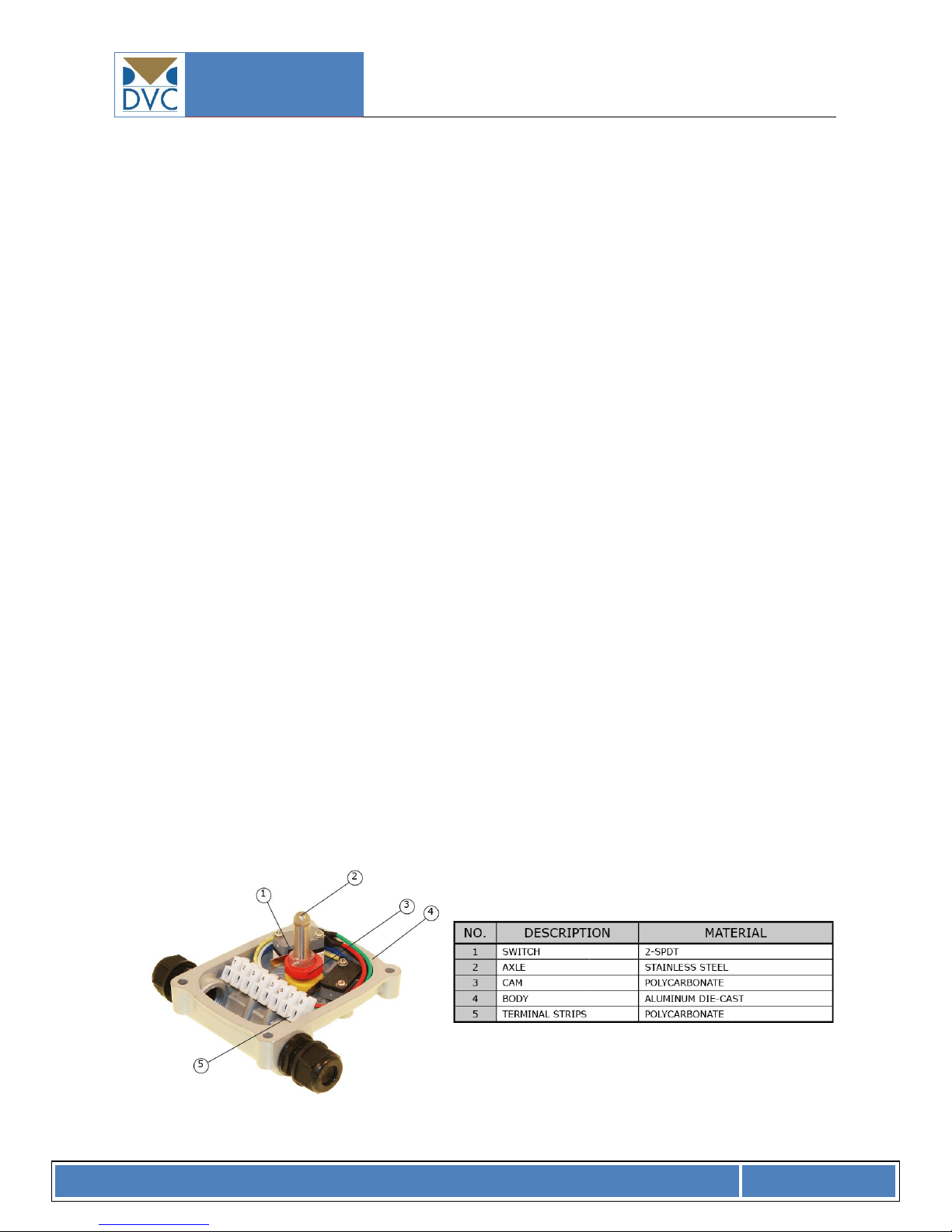
3.3 Internal parts / materials
5
3.4 Dimensions
6
4. Installation instructions
6
4.1 Pre-installation
6
4.2 Limit switch box mounting
6
4.3 Fitting the mounting bracket
7
4.4 Adjustment of the limit switch box
8
4.4.1 Open cam setting
8
4.4.2 Closed cam setting
8
4.4.3 Checking the switch cam setting
9
4.4.4 Wiring
9
4.4.5 Reassembly of limit switch box
9
5. Operation instructions
10
5.1 Electrical connections and preliminary test
10
5.2 Wiring
10
5.3 Operation
10
6. Maintenance
11
6.1 Maintenance
11

TYPE 5320
INSTALLATION, OPERATION AND MAINTENANCE MANUAL
I O M . U K . D V C . 5320. 300 6 15- R E V . B
PAGE 3
1. Introduction
1.1 Purpose
This installation and operating manual explains how to install, operate and maintain Type 5320 limit
switch boxes.
1.2 Safety notice
Safety notices in his manual stating precautions the user must take to reduce the risk of personal
injury and damage to the equipment. User must read these instructions before installation,
operating or maintenance is carried out.
DANGER: Refers to personal safety. Alert the user of danger or harm. The hazard or unsafe
practice will result in severe injury or death
WARNING: Refers to personal safety. Alert user of potential danger. Failure to follow
warning notices could result in personal injury or death
CAUTION: Directs the user’s attention to general precautions that, if not followed could result in
personal injury and/or damage

TYPE 5320
INSTALLATION, OPERATION AND MAINTENANCE MANUAL
I O M . U K . D V C . 5320. 300 6 15- R E V . B
PAGE 4
2. Product identification
2.1 Marking
The limit switch box name plate is located on the top cover casing. The name plate contains the
following:
Logo
Type number
Enclosure
Rated current
Accreditations, certifications
2.2 Initial inspection
When you receive the limit switch box, please make sure that the specifications of the limit switch
box (name plate) confirms with the customer order sheet and / or the required specifications.
Remove the packing wrap or carton box carefully. Inspect the product for any physical
damage that may have occurred during shipment or handling.
Check the product specification with your order. If something does not match the
requirements / differs from the expected, please contact us immediately for required
actions to be carried out.
2.3 Storage
Limit switch boxes must be stored in a clean, cool and dry area. The unit shall be stored with cover
installed and the conduit entries sealed. Storage must be off the floor, covered with a sealed dust
protector.
If limit switch boxes are to be stored outside before use / installation they must be stored off the
ground, high enough to prevent them from being immersed into water or covered with snow.
The conduit entries shall remain sealed until mounting of the power cable / signal cable takes
place.
TYPE 5320
INSTALLATION, OPERATION AND MAINTENANCE MANUAL
I O M . U K . D V C . 5320. 300 6 15- R E V . B
PAGE 5
Type
3. General information and features
The DVC type 5320 limit switches are designed for the use in various types of industries together
with small size valves i.e. butterfly valve, ball valves etc. for signaling / valve position monitoring
purposes.
3.1 Type 5320 standard technical data
Enclosure Rating Weatherproof IP67 & NEMA 4 & 4X
Enclosure High grade aluminum alloy
Ambient Temperature -20oC ~ + 80oC
Conduit Entries 2x M20
Travel Angle 90 degree +/- 10%
Position Indicator open: green, close: red
Switch Mechanical 2 x SPDT - Rating: 250VAC/16A, 125VAC/16A,
250VDC/0,3A, 125VDC/0,6A, 30VDC/10A
Terminal Strip 8 point
External Coating Chromate polyester powder coating
3.2 Type 5320 optional technical data
Enclosure Rating IP68
Enclosure High grade aluminum alloy
Conduit Entries 2x PF 1/2”, PT 1/2”, NPT 1/2”, PG 13,5
Switches Proximity switches
Indication Three way dome indication
3.3 Internal parts/materials
TYPE 5320
INSTALLATION, OPERATION AND MAINTENANCE MANUAL
I O M . U K . D V C . 5320. 300 6 15- R E V . B
PAGE 6
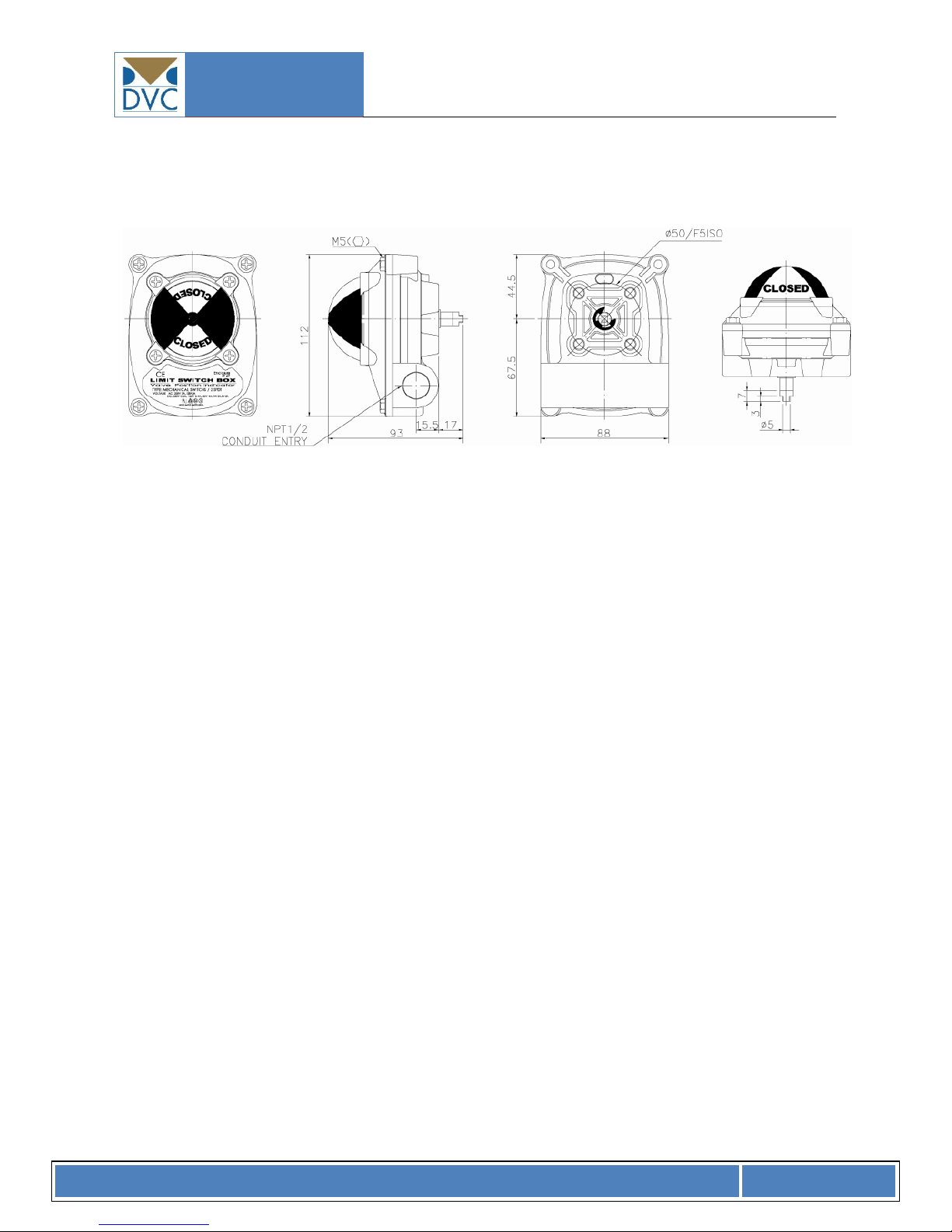
3.4 Dimensions
4. Installation instructions
4.1 Pre-installation
Verify that the nameplate of the limit switch box match the specifications needed – correct model
number, voltage and enclosure type - before installation and use.
Wiring connections should be in accordance with the diagram attached to the inside of the
top casing cover.
The two conduit cable entries shall be sealed in a proper manner until cable works is
finalized.
Position indicator and switch box covers are sealed by use of o-rings. Please take care of o-
ring in order not to cause any damage to the o-rings during disassembly or reassembly.
The position of the limit switches / cams have not been adjusted at the factory. Therefore a
final adjustment of those is needed before use.
Do not use in areas where explosion proof equipment is required. These types of limit
switches are designed as weatherproof types – not explosion proof types.
4.2 Limit switch box mounting
TYPE 5320
INSTALLATION, OPERATION AND MAINTENANCE MANUAL
I O M . U K . D V C . 5320. 300 6 15- R E V . B
PAGE 7
Note:
Prior to mounting of the limit switch box the item must be checked for any
damage
Damaged parts must be replaced by original spare parts
Mounting is most easily done with the actuator shaft pointing vertically upwards. But mounting is
also possible in any other position.
The limit switch box may be mounted in any position.
It is mandatory that the limit switch box is firmly secured t a sturdy mounting bracket High tensile
bolts or studs with spring locking washers must be used.
The limit switch box output shaft must be in line with the actuator shaft to avoid side-loading the
shaft. To avoid any backlash no flexibility in the mounting bracket or mounting should be allowed.
Caution: Make sure to cut off the electrical power before working on the limit switch box for
assembly, mounting etc.
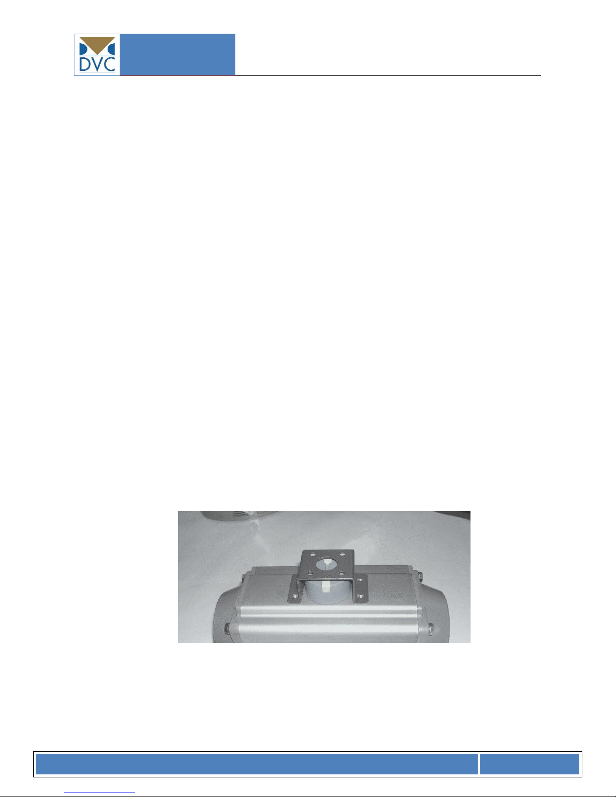
4.3 Fitting the mounting bracket
Two types of standard DVC mounting brackets are available
NAMUR VDE/VDI 3845 size 30x80
NAMUR VDE/VDI 3845 size 30x130
Fixed mounting bracket on top of actuator
The mounting bracket is fixed onto the top of the actuator by use of correctly sized high tensile
bolts and spring washers.
TYPE 5320
INSTALLATION, OPERATION AND MAINTENANCE MANUAL
I O M . U K . D V C . 5320. 300 6 15- R E V . B
PAGE 8
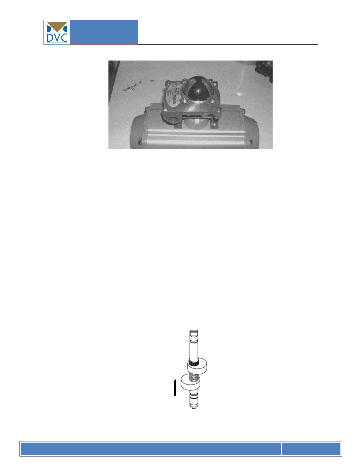
Insert the shaft of the limit switch box correctly into the drive slot on the top of the actuator drive
shaft – use correctly sized high tensile bolts and spring washers for fastening the box to the bracket.
4.4 Adjustment of the limit switch box
By use of screw driver loosen the captive bolt on the cover and lift off top cover.
Each switch has its own independent cam arrangement. Follow the procedures bellow for
adjustment.
4.4.1 Open cam setting
Lift the bottom cam up and turn it until the switch is activated (clicks) – then release the cam.
The spring will force the cam back into the splines on the shaft ensuring the correct position
of the cam.
Lift up and release

TYPE 5320
INSTALLATION, OPERATION AND MAINTENANCE MANUAL
I O M . U K . D V C . 5320. 300 6 15- R E V . B
PAGE 9
4.4.2 Closed cam setting
Push the top cam down and turn it until the switch is activated (clicks) – the release the cam.
The spring will force the cam back into the splines on the shaft ensuring the correct position
of the cam.
Push down and release
NOTE: It should be kept in mind that an incorrect setting of the cam position may/will
result in incorrect signaling to external control systems.
4.4.3 Checking the switch cam setting
Operate the actuator from full open to full closed in both directions several times to check
that the switch cams are operating correctly – preferably with a detection of the output
signal from the limit switches (if possible)
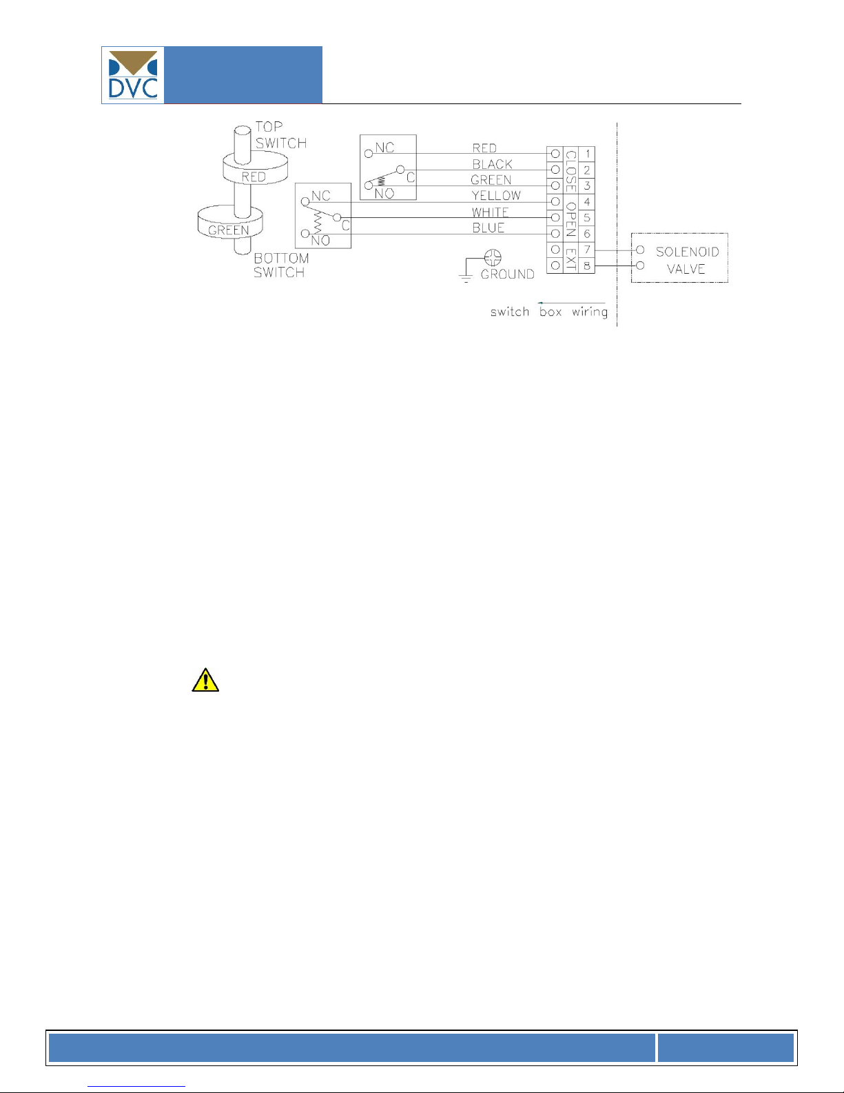
4.4.4 Wiring
The correct wiring diagram is attached onto the inside of the top casing cover. Please follow
the instructions carefully. If in doubt – please contact DVC.
TYPE 5320
INSTALLATION, OPERATION AND MAINTENANCE MANUAL
I O M . U K . D V C . 5320. 300 6 15- R E V . B
PAGE 10
Standard electrical diagram
Important: Earth wire cable shall be use in bicolor combination green/yellow
4.4.5 Reassembly of limit switch box
Carefully mount the top cover onto the bottom part of the casing – taking care not to
damage the o-ring.
5. Operation instructions
5.1 Electrical connections and preliminary test
WARNING:
Work on the electrical system or equipment must only be carried out by a skilled
electrician himself or by specially instructed personnel under the control and
supervision of such an electrician and in accordance with the applicable electrical
engineering rules
Cable gland or conduit entries shall be controlled by qualified engineers to ensure
correct protection against water damages etc.
Treat limit switch casing top with care. Gap between limit switch box housing parts
may lead to unexpected damages. Do not jam cover during fitting.

TYPE 5320
INSTALLATION, OPERATION AND MAINTENANCE MANUAL
I O M . U K . D V C . 5320. 300 6 15- R E V . B
PAGE 11
5.2 Wiring
Please refer to the enclosed wiring diagram or contact us for further details.
If the enclosed diagram is not followed/neglected – the guarantee will no longer be valid.
5.3 Operation
As to the fact that the limit switch are fully controlled/operated by the actuator shaft no manual
operation is necessary.
6. Maintenance
6.1 Maintenance
Caution:
Turn off all power services before attempting to perform service on the limit switch box.
Before removing or disassembling the limit switch box ensure that the valve or other
actuated device is isolated and not under pressure.
When/if replacing any part use only original DVC spare parts.
All though no real maintenance is necessary on the limit switch box, regular maintenance
checks should, under normal conditions, be carried out with intervals of maximum six
months. But if service conditions are severe more frequent inspections may be advisable.
Ensure limit switch box / actuator alignment
Ensure wiring insulation is intact, connected and terminated properly
Ensure all screws are present and tight
Ensure cleanliness of internal electrical parts / devices
Ensure conduits connections are installed properly and dry
Check enclosure o-ring seals and verify that the o-ring is not pinched between
flange
Visual inspect during open/close cycle
Inspect identification labels for wear and replace if necessary

TYPE 5320
INSTALLATION, OPERATION AND MAINTENANCE MANUAL
I O M . U K . D V C . 5320. 300 6 15- R E V . B
PAGE 12
WARNING:
Before starting work on the limit switch box, please check all conditions of the limit
switch box, other related equipment and site for safety purposes.
 Loading...