

Page 1
Manuale d’istruzioni
Instruction Manual
Notice d’Utilisation
Handbuch
Manual de Istrucciones
ADDOLCITORE ER
e VALVOLA ERV
D.M. 174/2004RIF. 03/18ER
Page 2

IT INDICE
1. PREMESSE E INFORMAZIONI GENERALI
1.1 SCOPO DEL MANUALE
1.2 CONSERVAZIONE DEL MANUALE
1.3 IDENTIFICAZIONE DELL’APPARECCHIO
1.4 DICHIARAZIONE DI CONFORMITÀ
1.5 NORME DI SICUREZZA IGIENICA
1.6 CONSIGLI UTILI E AVVERTENZE
2. CONOSCERE L’APPARECCHIO
2.1 DESCRIZIONE DELL’APPARECCHIO
2.2 ADDOLCIMENTO DELL’ACQUA
2.3 DESCRIZIONE DELL’ADDOLCITORE SERIE ER
2.4 DESCRIZIONE DELLA VALVOLA SERIE ERV
2.5 LA SCATOLA DELLA VALVOLA ERV CONTIENE
2.6 LA SCATOLA DELLA BOMBOLA CONTIENE
2.7 CARATTERISTICHE TECNICHE
2.8 QUANTITÀ DI ACQUA ADDOLCITA
3. INSTALLAZIONE
3.1 IMBALLO
3.2 SCELTA DEL LUOGO PER L’INSTALLAZIONE
3.3 COLLEGAMENTO ALLA RETE IDRICA
3.4 RACCORDI RAPIDI
4. MANUTENZIONE PER L’INSTALLATORE
4.1 MESSA IN SERVIZIO/SOSTITUZIONE
4.2 ISTRUZIONI PER LA CORRETTA MESSA IN SERVIZIO/
SOSTITUZIONE DELLA BOMBOLA
4.3 RIGENERAZIONE
- IMMAGAZZINAGGIO
5. REGOLAZIONE DELLA DUREZZA DELL’ACQUA
TRAMITE MISCELATORE
6. USO IMPROPRIO DELL’APPARECCHIO
7. SMALTIMENTO DELL’APPARECCHIO
8. PROBLEMI E RISOLUZIONI
PROBLEMI E SOLUZIONI VALVOLA ERV
PROBLEMI E SOLUZIONI BOMBOLA ER
UK INDEX
1. INTRODUCTION AND GENERAL INFORMATION
1.1 SCOPE OF THE USER MANUAL
1.2 MANUAL STORAGE
1.3 EQUIPMENT ID
1.4 DECLARATION OF CONFORMITY
1.5 SANITARY SECURITY RULES
1.6 USEFUL INFORMATION AND ASSORTED NOTES
2. EQUIPMENT OVERVIEW
2.1 OPERATING PRINCIPLE
2.2 WATER SOFTENING
2.3 ER SERIES SOFTENER DESCRIPTION
2.4 ERV SERIES VALVE DESCRIPTION
2.5 ERV VALVE BOX DESCRIPTION
2.6 ER CYLINDER BOX DESCRIPTION
2.7 TECHNICAL FEATURES
2.8 AMOUNT / QUANTITY / LITERS OF SOFTENED WATER
3. INSTALLATION
3.1 PACKAGE
3.2 CHOOSING THE RIGHT INSTALLATION SPOT
3.3 CONNECTION TO THE WATER SUPPLY SYSTEM
3.4 QUICK PIPE COUPLINGS
4. MAINTENANCE TO BE CARRIED OUT BY THE
INSTALLER
4.1 PUTTING INTO SERVICE / REPLACEMENT
4.2 INSTRUCTIONS ON CORRECT CYLINDER PUT-INTOSERVICE/REPLACEMENT
4.3 REGENERATION
- STORAGE
5. ADJUSTING WATER HARDNESS BY USING A MIXING
PIECE
2
ATTENZIONE: il presente libretto costituisce parte integrante del prodotto e dovrà essere consegnato all’installatore,
il quale a sua volta lo riconsegnerà all’utente dopo avere compilato la tabella del controllo e data ultimo controllo
6. EQUIPMENT MISUSE
7. EQUIPMENT DISPOSAL
8. TROUBLESHOOTING
- ERV VALVE TROUBLESHOOTING
- ER CYLINDER TROUBLESHOOTING
F INDEX
1. PREAMBULE ET INFORMATIONS GENERALES
1.1 BUT DU MANUEL
1.2 STOCKAGE DU MANUEL
1.3 IDENTIFICATION DE L’APPAREIL
1.4 DECLARATION DE CONFORMITE
1.5 REGLES D’HYGIENES ET DE SECURITE
1.6 INFORMATIONS UTILES ET CONSEILS PRATIQUES
2. APERÇU DEL’APPAREIL
2.1 DESCRIPTIF DE L’APPAREIL
2.2 ADOUCISSEMENT DE L’EAU
2.3 DESCRIPTIF DE L’ADOUCISSEUR SERIE ER
2.4 DESCRIPTIF DE LA VANNE SERIE ERV
2.5 DESCRIPTIF DE L’EMBALLAGE DE LA VANNE ERV
2.6 DESCRIPTIF DE L’EMBALLAGE DE LA BOUTEILLE ER
2.7 CARACTERISTIQUES TECHNIQUES
2.8 QUANTITE D’EAU ADOUCIE
3. INSTALLATION
3.1 EMBALLAGE
3.2 CHOIX DU LIEU D’INSTALLATION
3.3 RACCORDEMENT AU RESEAU D’EAU
3.4 RACCORDS RAPIDES
4. ENTRETIEN QUI DOIT ÊTRE REALISE PAR LE
TECHNICIEN D’INSTALLATION
4.1 MISE EN SERVICE / REMPLACEMENT
4.2 MODE D’EMPLOI POUR LA CORRECTE MISE EN
SERVICE / LE REMPLACEMENT DE LA BOUTEILLE
4.3 REGENERATION
- STOCKAGE
5. REGLAGE DE LA DURETE DE L’EAU PAR UN
MELANGEUR
6. MAUVAISE UTILISATION DE L’APPAREIL
7. ELIMINATION DE L’APPAREIL
8. PROBLEMES ET RESOLUTIONS DES PROBLEMES
PROBLEMES ET SOLUTIONS POUR LA VANNE ERV
PROBLEMES ET SOLUTIONS POUR LA BOUTEILLE ER
D INHALTSVERZEICHNIS
1. VORAUSSETZUNGEN UND ALLGEMEINE
INFORMATIONEN
1.1 ZWECK DIESES HANDBUCHS
1.2 AUFBEWAHRUNG DES HANDBUCHS
1.3 GERÄTEIDENTIFIKATION
1.4 KONFORMITÄTSERKLÄRUNG
1.5 HYGIENISCHE SICHERHEITSSTANDARDS
1.6 NÜTZLICHE TIPPS UND HINWEISE
2. DAS GERÄT KENNEN
2.1 FUNKTIONSPRINZIP
2.2 WASSERENTHÄRTUNG
2.3 BESCHREIBUNG DES WASSERENTHÄRTERS DER ERSERIE
2.4 BESCHREIBUNG DES VENTILS DER ERV-SERIE
2.5 DER KARTON DES ERV-VENTILS ENTHÄLT
2.6 DER KARTON DER ER-FLASCHE ENTHÄLT
2.7 TECHNISCHE EIGENSCHAFTEN
2.8 ENTHÄRTETE WASSERMENGE
3. INSTALLATION
3.1 VERPACKUNG
3.2 WAHL DES INSTALLATIONSORTES
3.3 ANSCHLUSS AN DIE WASSERLEITUNG
3.4 SCHNELLANSCHLÜSSE
Page 3
4. WARTUNG FÜR DEN INSTALLATEUR
4.1 INBETRIEBNAHME/AUSTAUSCH
4.2 ANWEISUNGEN FÜR DIE KORREKTE INBETRIEBNAHME/
AUSTAUSCH DER FLASCHE
4.3 REGENERATION
- LAGERUNG
5. REGULIERUNG DER WASSERHÄRTE DURCH
MISCHER
6. UNSACHGEMÄSSER GEBRAUCH DES GERÄTES
7. ENTSORGUNG DES GERÄTES
8. PROBLEME UND LÖSUNGEN
PROBLEME UND LÖSUNGEN DES ERV-VENTILS
PROBLEME UND LÖSUNGEN DER ER-FLASCHE
E ÌNDICE
1. INTRODUCCIÓN E INFORMACIÓN GENERAL
1.1 PROPÓSITO DEL MANUAL
1.2 CONSERVACIÓN DEL MANUAL
1.3 IDENTIFICACIÓN DEL EQUIPO
1.4 DECLARACIÓN DE CONFORMIDAD
1.5 NORMAS DE SEGURIDAD HIGIÉNICA
1.6 CONSEJOS ÚTILES Y ADVERTENCIAS
2. CONOCER EL EQUIPO
2.1 PRINCIPIO DE FUNCIONAMIENTO
2.2 DESCALCIFICACIÓN DEL AGUA
2.3 DESCRIPCIÓN DEL DESCALCIFICADOR SERIE ER
2.4 DESCRIPCIÓN DE LA VÁLVULA SERIE ERV
2.5 LA CAJA DE LA VÁLVULA ERV CONTIENE
2.6 LA CAJA DE LA BOMBONA ER CONTIENE
2.7 CARACTERÍSTICAS TÉCNICAS
2.8 CANTIDAD DE AGUA DESCALCIFICADA
3. INSTALACIÓN
3.1 EMBALAJE
3.2 ELECCIÓN DEL LUGAR PARA LA INSTALACIÓN
3.3 CONEXIÓN A LA RED DE SUMINISTRO DE AGUA
3.4 CONEXIONES RÁPIDAS
4. MANTENIMIENTO PARA EL INSTALADOR
4.1 PUESTA EN SERVICIO/SUSTITUCIÓN
4.2 INSTRUCCIONES PARA LA CORRECTA PUESTA EN
SERVICIO/SUSTITUCIÓN DE LA BOMBONA
4.3 REGENERACIÓN
- ALMACENAJE
5. REGULACIÓN DE LA DUREZA DEL AGUA MEDIANTE
MEZCLADOR
6. USO INCORRECTO DEL EQUIPO
7. ELIMINACIÓN DEL EQUIPO
8. LOCALIZACIÓN DE AVERÍAS
LOCALIZACIÓN DE AVERÍAS VÁLVULA ERV
LOCALIZACIÓN DE AVERÍAS BOMBONA ER
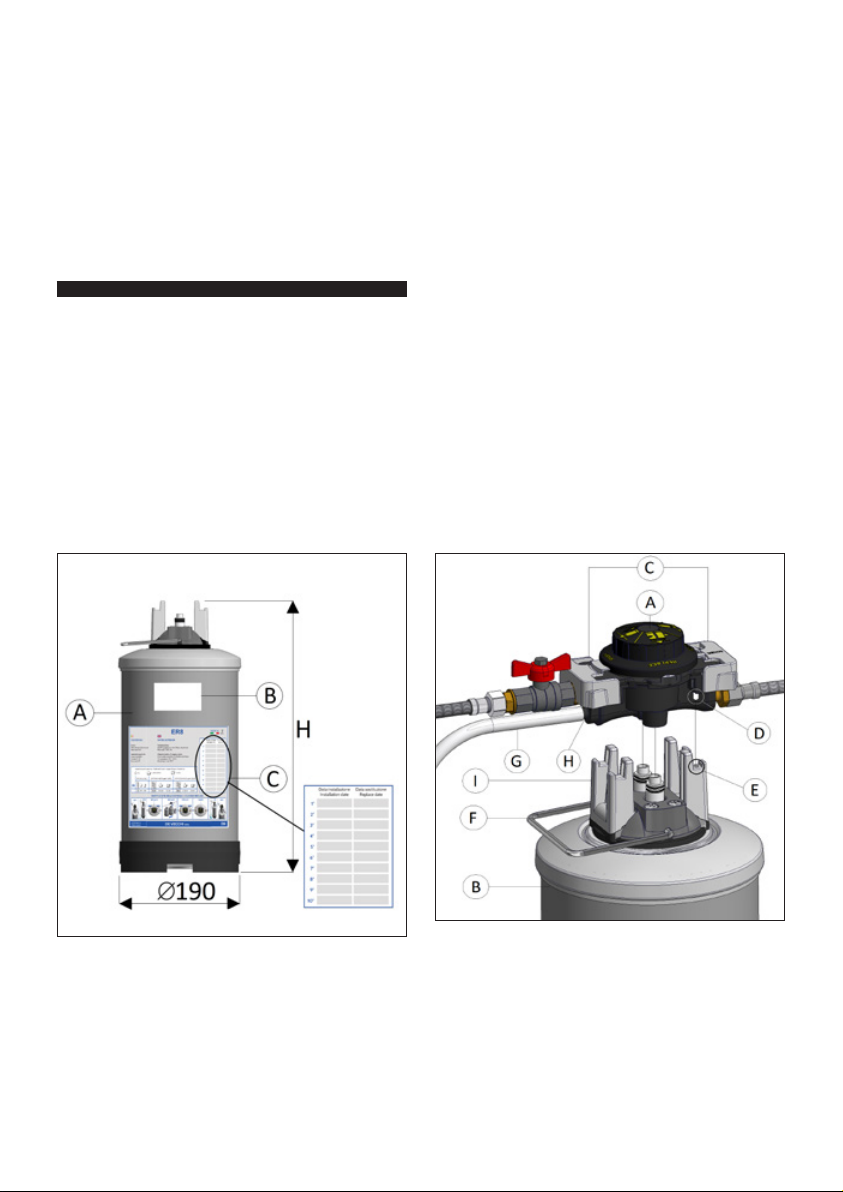
FIG. 1
FIG. 2
LEGENDA (fig. 2):
A VALVOLA
LEGENDA (fig. 1):
A BOMBOLA
B ETICHETTA
C TAB.REGITRAZIONE
INST./SOST.
LEGEND (fig. 1):
A CYLINDER
B LABEL
C LOG TABLE
IN SERVICE/REPLACE-
MENT
B BOMBOLA
C BLOCCHI LATERALI
D PERNO DI RIFERIMENTO
E FORO DI RIFERIMENTO
F MANIGLIA
G TUBO SCARICO
H PORTA CANNA
I FLANGIA
WARNING: This leaflet is an integral part of the machine and must be handed to the installer, who in turn should
hand it back to the user after having filled in the check table
LEGEND (fig. 2):
A VALVE
B CYLINDER
C SIDE BLOCKS
D PIN MATCH
E HOLE MATCH
F HANDLE
G DRAIN PIPE
H PIPE-HOLDER
I COLLAR
3
Page 4
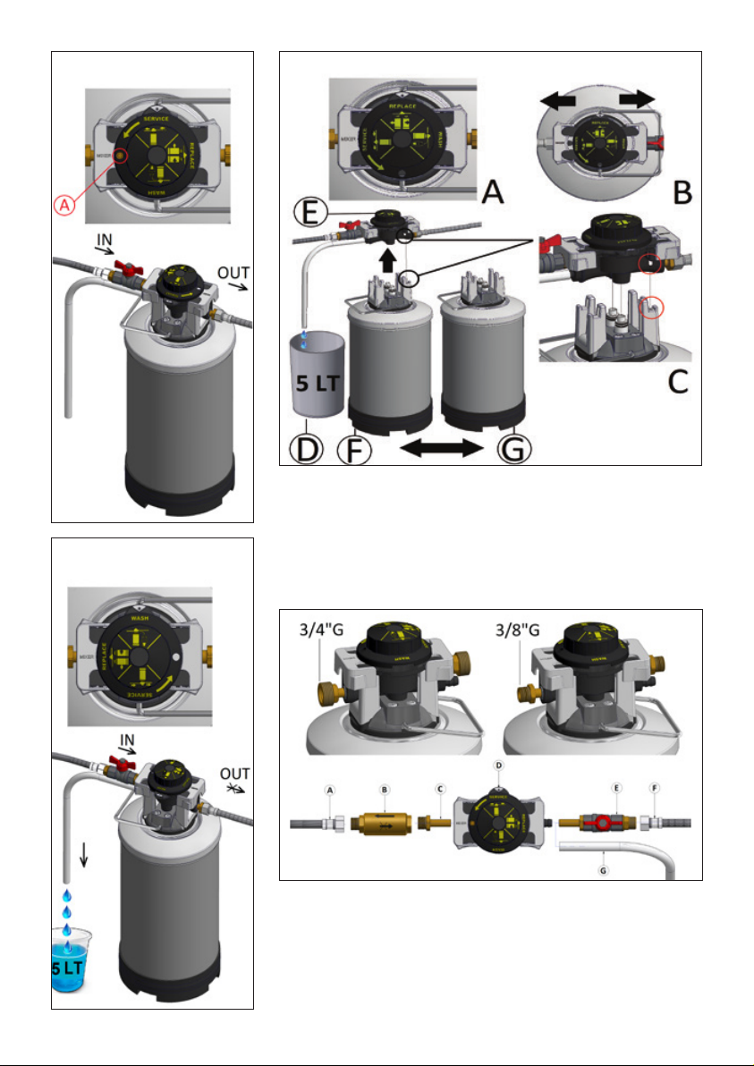
SERVICE REPLACE
FIG. 4
FIG. 3
FIG. 5
WASH
LEGENDA (fig. 4):
A POSIZIONE SERVIZIO
B POSIZIONE REPLACE
C RIFERIMENTO INCASTRO
D SECCHIO
E VALVOLA ERV
F BOMBOLA ESAUSTA
G BOMBOLA NUOVA/RIGEN.
FIG. 6
LEGENDA (fig. 6):
A TUBO D’USCITA
B VALVOLA NON RITORNO
C RACCORDO D’USCITA
D VALVOLA ERV
E RUBINETTO
F TUBO D’INGRESSO
G TUBETTO DI SCARICO
LEGEND (fig. 4):
A SERVICE POSITION
B REPLACE POSITION
C LOCK MATCH
D BUCKET
E ERV VALVE
F DEPLETED CYLINDER
G NEW/REG.ED CYLINDER
LEGEND (fig. 6):
A OUTFLOW PIPE
B NON-RETURN VALVE
C OUTFLOW COUPLING
D ERV VALVE
E TAP
F INFLOW PIPE
G SMALL DRAIN PIPE
4 Manuale d’istruzioni ADDOLCITORE ER e VALVOLA ERV
Page 5
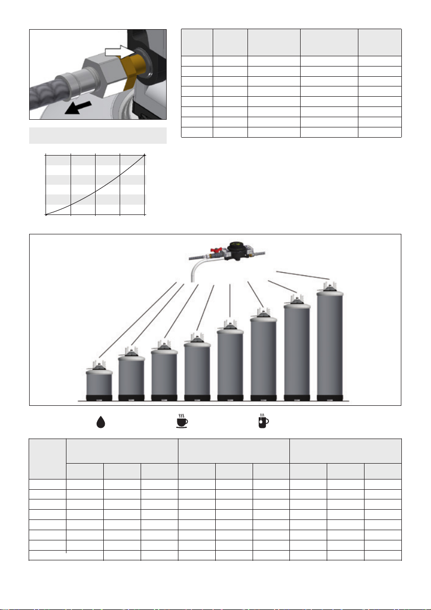
FIG. 7
Litres of soft water * # coffee cups (0.03 l) * # tea cups (0.1 l)
DIAGRAMMA PERDITE DI CARICO
PRESSURE LOSS CHARACTERITICS
BAR
3
2,5
2
1,5
1
0,5
0
0 240 432
600 912
Modello Altezza Peso Litri resina Peso pieno
Model Height Weight Resin Liters Full weight
(H mm) (Kg) (l)
ER5 370 5 3,85 7
ER8 470 8 5,6 10,2
ER10 520 9 6,51 12
ER12 570 10 7,35 13,6
ER14 670 13 9,1 16,4
ER16 770 15 10,99 19,5
ER18 870 18 12,6 22,5
ER20 970 20 14,35 26
LT/H
FIG. 8
Legenda TABELLA 1:
litri Acqua addolcita * n. caffè (0.03 l) * n. Tea (0.1 l)
Legend TAB. 1:
MODELLO
MODEL
ER
5
8
10
12
14
16
18
20
LITRI
LITERS
1050
1680
2100
2520
2940
3360
3780
4200
20 °f
11 °D
200 PpmCaCo
CAFFÈ
COFFEE
31500
50400
63000
75600
88200
100800
113400
126000
3
TÉ
TEA
10500
16800
21000
25200
29400
33600
37800
42000
LITRI
LITERS
700
1120
1400
1680
1960
2240
2520
2800
30 °f
16 °D
300 PpmCaCo
CAFFÈ
COFFEE
21000
33600
42000
50400
58800
67200
75600
84000
3
TÉ
TEA
7000
11200
14000
16800
19600
22400
25200
28000
LITRI
LITERS
525
840
1050
1260
1470
1680
1890
2100
40 °f
22 °D
400 PpmCaCo
CAFFÈ
COFFEE
15750
25200
31500
37800
44100
50400
56700
63000
* I dati dei numeri di caffè e tea indicati nella tabella, sono un calcolo teorico, nella pratica i numeri possono cambiare.
*
Data pertaining to coffee and tea cups number included in the table are theoretical; consequently, they might be different in actual terms.
WARNING: This leaflet is an integral part of the machine and must be handed to the installer, who in turn should
hand it back to the user after having filled in the check table
3
TÉ
TEA
5250
8400
10500
12600
14700
16800
18900
21000
5
Page 6

manuale
d’istruzioni
ADDOLCITORE ER e VALVOLA ERV
ITALIANO
AVVERTENZE PER L’UTENTE
- Questa macchina non deve essere utilizzata da bambini
o da persone con ridotte capacità fisiche, mentali o sensoriali, o prive di esperienza, almeno che esse non siano
supervisionate da persone responsabili della loro sicurezza,
o abbiano ricevuto istruzioni riguardo il corretto e sicuro
utilizzo della macchina e i pericoli che corrono.
- Non cercare di fare riparazioni da soli, si potrebbero causare danni, rivolgersi al vostro installatore.
- Non toccare o utilizzare l’addolcitore con mani o piedi bagnati, umidi o scalzi.
1) PREMESSE E INFORMAZIONI GENERALI
1.1 SCOPO DEL MANUALE
Questo libretto d’istruzioni è destinato a personale qualificato,
che sia a conoscenza delle normative di sicurezza igienica del
luogo di installazione.
Lo scopo del manuale è di fornire tutte le informazioni utili e le
avvertenze per l’installatore:
- Le precauzioni per la sicurezza igienica
- La descrizione e caratteristiche dell’apparecchio
- Il luogo e modalità di installazione
- La messa in servizio
- Le procedure da adottare dopo periodi di inattività dell’apparecchio
- Le avvertenze per la cura e la pulizia dell’apparecchio
- Lo smaltimento
- Le risoluzione di eventuali problemi
• Per l’utente
- Le istruzioni per la sostituzione dell’addolcitore
- Le avvertenze per la cura e la pulizia dell’apparecchio
- Le avvertenze igieniche e sanitarie relative all’acqua prodotta dall’apparecchio
L’inosservanza delle seguenti disposizioni comporta la decadenza di responsabilità del produttore, da eventuali danni cagionati a persone, cose o animali e la decadenza di qualsiasi
garanzia sull’apparecchio.
Il libretto ha anche lo scopo di indicare le responsabilità
dell’installatore ed evitare che venga fatto un uso improprio
dell’apparecchio, quindi vi consigliamo di leggere questo
manuale prima di installare o utilizzare l’apparecchio.
1.2 CONSERVAZIONE DEL MANUALE
Il presente libretto costituisce parte integrante ed essenziale
del prodotto. Esso va conservato con cura dall’utente e
dovrà sempre accompagnare l’apparecchio, anche in
caso di sua cessione ad altro proprietario o utente.
1.3 IDENTIFICAZIONE DELL’APPARECCHIO
L’addolcitore è identificato dalle cifre in grassetto scritte in
basso a sinistra sull’etichetta posta sulla bombola (fig.1, B).
1.4 DICHIARAZIONE DI CONFORMITÀ
L’apparecchio è realizzato in conformità delle
Regolamentazioni Comunitarie e leggi nazionali applicabili nel
momento della sua immissione sul mercato.
Non rientrano nell’ALLEGATO IV della DIRETTIVA 2006/42/CE,
il Costruttore provvede al percorso di autocertificazione per
l’apposizione della marcatura CE posta sull’etichetta attaccata
al contenitore del sale.
La dichiarazione di conformità sottoscritta dal costruttore è
sempre a disposizione su richiesta e sul sito.
1.5 NORME DI SICUREZZA IGIENICA
Si rende NECESSARIO per le riparazioni e la manutenzione
ordinaria e straordinaria l’utilizzo di ricambi originali per garantire la sicurezza igienica prestazionale.
Per preservare la sicurezza igienica si raccomanda di disimballare l’apparecchio solo al momento della sua effettiva installazione.
Le bombole ER subiranno movimentazione dal luogo di installazione al luogo di rigenerazione, si rendono necessarie delle
norme basilari da seguire.
Sarà responsabilità dell’incaricato averne cura durante la sua
movimentazione
- Non trasportare o stoccare le bombole in ambienti dove è
evidente una violazione igienica.
- Evitare che animali o insetti si avvicinino pregiudicandone la
salubrità.
- Non utilizzare le bombole se sono state abbandonate in
luoghi non presidiati da personale competente.
- Nel dubbio, non utilizzare mai una bombola a rischio, o di
cui non si conosca la provenienza.
- Non utilizzare una bombola manomessa, danneggiata o
riparata da sconosciuti.
- Nel caso la bombola sia stata posta in luoghi poco igienici
o venuta a contatto con animali o sostanze pericolose, non
utilizzarla.
I luoghi dove la bombola dovrà stazionare per installazione-trasporto-rigenerazione e immagazzinaggio, dovranno essere ambienti in cui non vengano violate le norme igieniche
e di sicurezza.
1.6 CONSIGLI UTILI E AVVERTENZE
Per lo stoccaggio:
- Immagazzinare l’addolcitore in un luogo asciutto e pulito
- la temperatura di stoccaggio deve essere compresa tra
4 - 35 °C
Per l’installatore:
Vi consigliamo di installare l’apparecchio dopo aver letto attentamente le istruzioni del presente manuale e Vi suggeriamo
in caso di difficoltà, di chiedere l’assistenza del vostro rivenditore i cui dati sono riportati nell’ultima pagina del libretto.
Questo apparecchio non deve essere utilizzato da bambini o
da persone con ridotte capacità fisiche, mentali, sensoriali, o
prive di esperienza a meno che esse non siano supervisionate
da persone responsabili della loro sicurezza, o abbiano ricevuto istruzioni riguardo il corretto e sicuro utilizzo della macchina
e i pericoli che corrono.
Non cercare di eseguire riparazioni da soli, si potrebbero causare danni. Rivolgersi sempre al Vostro installatore.
Non toccare o utilizzare l’apparecchio con mani o piedi bagnati, umidi o scalzi.
La ditta produttrice non è responsabile di eventuali danni
e/o infortuni che possano derivare dalla mancata osservanza di queste precauzioni.
2) CONOSCERE L’APPARECCHIO
2.1 DESCRIZIONE DELL’APPARECCHIO
Per il corretto e duraturo funzionamento di tutte le macchine che producono bevande utilizzando l’acqua potabile della
rete idrica, è indispensabile che esse siano alimentate con
acqua addolcita, ossia priva dei sali della durezza Ca (Calcio)
e Mg (Magnesio) responsabili della formazione di incrostazioni
calcaree.
L’addolcitore è un apparecchio che, utilizzando le resine a
scambio ionico contenute nella sua bombola, è in grado di
eliminare la durezza dell’acqua.
Le resine cationiche, contenute nella bombola, hanno la proprietà di trasformare il carbonato di calcio (calcare), in car-
6 Manuale d’istruzioni ADDOLCITORE ER e VALVOLA ERV
Page 7

manuale
d’istruzioni
ADDOLCITORE ER e VALVOLA ERV
ITALIANO
bonato di sodio, il quale è solubile in acqua alle temperature
normalmente presenti nelle macchine da caffè, nei produttori
di ghiaccio e nei distributori automatici di bevande.
La cessione continua di ioni sodio da parte delle resine, indispensabili per l’addolcimento dell’acqua potabile, tende ad
esaurirsi in proporzione alla portata e al consumo dell’acqua
sino al loro esaurimento. È necessaria, quindi, la loro rigenerazione effettuata per mezzo del passaggio di acqua e sale
da cucina attraverso le resine, riportando le stesse allo stato
attivo d’origine.
Le resine riducono gradualmente, in funzione del numero di
riattivazioni, la loro funzione cationica e conseguentemente
l’efficienza.
2.2 ADDOLCIMENTO DELL’ACQUA
Di seguito vengo elencate le reazioni chimiche principali che
caratterizzano lo scambio ionico che avviene durante il processo di addolcimento dell’acqua tramite l’utilizzo delle resine
cationiche forti in forma NA+
Ca(HCO3)2 [bicarbonato di calcio] ---resina Na--- 2NaHCO
Mg(HCO3)2 [bicarbonato di magnesio]
CaSO4 [solfato di calcio] ---resina Na--- 2NaHSO
MgSO4 [solfato di magnesio] ---resina Na--- 2NaHSO
CaCl2 [cloruro di calcio] ---resina Na--- 2NaCl
MgCl2 [cloruro di magnesio] ---resina Na--- 2NaCl
2.3 DESCRIZIONE DELL’ADDOLCITORE SERIE ER
L’addolcitore della SERIE ER è costituito da due componenti
che dovranno essere agganciati tra loro.
Il primo è la valvola ERV installata tra la rete idrica e la macchina da alimentare con acqua addolcita (fig. 2, A).
La valvola è innestata sulla bombola e fermata da due blocchi
laterali scorrevoli (fig. 2, C).
Il secondo è la bombola ER (fig. 2,B) intercambiabile. Unendo
la valvola con la bombola si forma l’addolcitore. Per garantire
il corretto funzionamento delle macchine alle quali l’addolcitore è applicato, occorre sostituire con regolarità la bombola
esausta con una rigenerata. Grazie alla rapida disconnessione
e alla pratica maniglia (fig. 2, F), sarà comodo rimuovere la
bombola per essere rigenerata dal tecnico dell’ assistenza.
Nota: Dopo 10 volte che la bombola viene rigenerata consigliamo di sostituirla con una nuova.
La SERIE ER offre 8 modelli di diversa capacità:
ER5, ER8, ER10, ER12, ER14, ER16, ER18, ER20 (fig. 8).
2.4 DESCRIZIONE DELLA VALVOLA SERIE ERV
La valvola ERV collegata alla rete idrica, consente l’ingresso
dell’acqua nella bombola SERIE ER ed ha tre funzioni selezionabili ruotando una manopola.
1. SERVICE (LAVORO), è la posizione in cui l’acqua passa
all’interno della bombola, va a contatto con le resine, viene
addolcita e poi mandata all’utenza (fig. 3).
2. REPLACE (SOSTITUZIONE DELLA BOMBOLA), è la po-
sizione di sostituzione dell’addolcitore (fig.4, A). L’acqua,
durante la sostituzione, viene erogata senza essere stata
addolcita.
3. WASH (CONTROCORRENTE), in questa funzione l’ac-
qua passa attraverso le resine, ma in direzione contraria,
uscendo dal tubo di scarico (fig. 5). In questa fase non va
acqua all’uscita.
La valvola è dotata di un miscelatore che permette di lasciare
un residuo di durezza nell’acqua in uscita dall’addolcitore
(vedi capitolo 5).
La valvola ERV può essere connessa a tutti i tipi di bombole
(fig.8).
---resina Na--- 2NaHCO
2.5 LA SCATOLA DELLA VALVOLA ERV CONTIENE
• 1 valvola ERV
• 1 libretto d’istruzioni
• 1 tubo per lo scarico
• 2 raccordi da 3/8”G o da 3/4”G (fig.6, C) per collegare la
valvola alla macchina da alimentare
• 1 rubinetto d’ingresso da 3/8”G o da 3/4”G (fig.6, E) per
collegare la valvola alla rete idrica
2.6 LA SCATOLA DELLA BOMBOLA CONTIENE
• 1 bombola SERIE ER (fig. 1)
• 1 libretto di istruzioni
2.7 CARATTERISTICHE TECNICHE
Portata nominale a 4 bar ..... 800 l/h
Temperatura ambiente:...... 4°C - 35°C
Attacchi allacciamento idrico: . 3/8”G; 3/4”G
• Caratteristiche dell’acqua d’alimento:
- l’acqua d’alimento deve essere potabile e limpida
- temperatura: 6°C÷ 25°C
- pressione: 0,1 MPa ÷ 0,8 MPa (1 ÷ 8 bar)
3
- durezza massima: 900 ppm (90°f)
3
4
2.8 QUANTITÀ D’ACQUA ADDOLCITA
4
Nella tabella n.1 è indicata la quantità d’acqua addolcita che
ER è in grado di erogare, a secondo del modello, prima di
essere rigenerato.
La quantità d’acqua che ogni addolcitore è in grado di erogare, varia in base alla sua durezza e alle dimensioni delle
bombole.
Sono inoltre indicati quanti caffè e tea si possono erogare con
le diverse bombole.
Per esempio: se una bombola ER8 dovrà addolcire un’acqua
di durezza pari a 30°f, erogherà 1120 litri pari a 33600 caffè
o 11200 tea.
3) INSTALLAZIONE
3.1 IMBALLO
• Prima dell’installazione accertarsi che la valvola e la bombola non presentino anomalie o danni causati dal trasporto;
nel dubbio rivolgersi al rivenditore.
• Conservare per qualche tempo la scatola dell’imballo avendo cura di non lasciare pezzi dell’imballo pericolosi o piccoli
alla portata dei bambini.
3.2 SCELTA DEL LUOGO PER L’INSTALLAZIONE
• Verificare se a monte del punto di installazione dell’appa-
recchio non sia già presente un qualunque sistema di trattamento.
• Verificare che il prelievo dell’acqua avvenga da una tubazio-
ne dove scorre acqua potabile. Si consiglia di effettuare una
verifica dei parametri chimico-fisici e durezza dell’acqua
potabile in ingresso prima della installazione.
• Installare l’apparecchio in un luogo asciutto e facilmente
accessibile per le operazioni di manutenzione, sostituzione
e pulizia; non installare la valvola in posti sporchi dove manchino i principi di igienicità o in cui sia difficile fare pulizia.
• Non installare in ambienti in cui c’è un evidente violazione
delle norme di sicurezza elettrica o antinfortunistica e/o igienica.
• Verificare che la temperatura dell’ambiente sia compresa
tra 4°C e 35°C.
• Tenere lontano dai prodotti acidi o corrosivi.
La pressione idrica non deve essere inferiore a 0.1 Mpa (1
bar) o superiore a 0.8 Mpa (8 bar) (si consiglia almeno 3 o
Manuale d’istruzioni ADDOLCITORE ER e VALVOLA ERV 7
Page 8

manuale
d’istruzioni
ADDOLCITORE ER e VALVOLA ERV
ITALIANO
4 bar).
Nel caso la pressione superi gli 8 bar occorre installare un
riduttore di pressione.
3.3 COLLEGAMENTO ALLA RETE IDRICA
Il collegamento con la rete idrica deve essere fatto in ottemperanza con le norme vigenti, secondo le istruzioni del produttore e da personale qualificato.
Durante l’installazione oltre ad usare tubi, raccordi, valvole
e componenti conformi al DM 174/2004 preservare la loro
integrità igienica nella confezione originale fino al momento
del montaggio, è vietato usare materiali e componenti non
idonei al contatto con acqua potabile conservati in modo igienicamente inadeguato in quanto potrebbero compromettere la
qualità dell’acqua trattata e l’apparecchiatura.
Verificare che:
- Il tubo d’entrata dell’acqua abbia un diametro interno di
almeno 7 mm (fig. 6, F).
- Si consiglia di installare sul tubo d’uscita una valvola di non
ritorno (fig. 6, B) (DVGW, DIN 1988 T2), per preservare l’addolcitore da eventuali ritorni di acqua calda che potrebbero
danneggiarlo.
- Controllare che tutti i tubi siano liberi, non schiacciati e
senza strozzature.
-Collegare il tubo dell’entrata dell’acqua con il rubinetto (fig.
6, E, F.).
- Collegare il raccordo di uscita con la valvola di non ritorno e
con il tubo di uscita (fig. 6, A, B, C).
- Collegare il rubinetto e il raccordo di entrata alla valvola
inserendoli fino in battuta (fig. 7).
- Ruotare la manopola su “REPLACE” (fig.4, A) e scorrere i
due perni verso l’esterno (fig.4, B), aprire il rubinetto dell’acqua e verificare che non ci siano perdite.
- Collegare il tubetto di scarico (fig.6, G).
3.4 RACCORDI RAPIDI
Le connessioni dei tubi con la valvola sono realizzate con
attacchi rapidi.
Per collegare un tubo occorre inserirlo fino in battuta, gli inserti metallici della connessione rapita impediscono al tubo
di fuoriuscire.
Per scollegare il rubinetto o il tubo occorre scaricare l’eventuale pressione, quindi premere l’anello nero che lo circonda
in prossimità dell’inserimento e sfilarlo (fig.7).
4) MANUTENZIONE PER L’INSTALLATORE
4.1 MESSA IN SERVIZIO/SOSTITUZIONE
Prima di collegare la valvola ERV alla bombola, accertarsi non
vi siano evidenti anomalie o danni causati dal trasporto; nel
dubbio rivolgersi al rivenditore.
Le operazioni per la messa in servizio e la sostituzione della
bombola sono molto simili.
4.2 ISTRUZIONI PER LA CORRETTA MESSA IN
SERVIZIO/SOSTITUZIONE DELLA BOMBOLA
1. Per scaricare l’acqua necessaria alla messa in servizio
e alla sostituzione, posizionare il tubetto di scarico in un
pozzetto oppure usare un secchio con capacità di almeno
8 litri.
2. Accertarsi che il tubo di scarico (fig.2, G) sia ben inserito
sul porta-canna della valvola (fig. 2, H), quindi mettere
l’altra estremità del tubo nello scarico o nel secchio considerando che, durante le operazioni seguenti usciranno
circa 5 litri di acqua.
3. Ruotare la manopola della valvola ERV su REPLACE (fig. 4,
A) attendere 10 secondi.
4. Far scorrere i due blocchi laterali verso l’esterno fino alla
loro posizione di apertura (fig. 4, B), estrarre la valvola
dalla bombola esaurita (fig.4, E).
5. Inserire la valvola nella bombola rigenerata/nuova (fig.4,
G), facendo coincidere il perno con il foro della flangia
posto sulla bombola (fig.4, C).
6. Far scorrere i due blocchi laterali verso l’interno fino alla
loro posizione di chiusura (fig.4).
7. Ruotare la manopola su WASH, (fig.5) e lasciare uscire dal
tubo di scarico circa 5 litri d’acqua, verificare che l’acqua
scaricata sia limpida.
8. Ruotare la manopola su SERVICE (fig. 3).
9. Verificare che non esca acqua dal tubo di scarico e che
non ci siano perdite.
10. Segnare la data di inizio lavoro sull’etichetta della bombola (fig.1, C).
4.3 RIGENERAZIONE
Una volta sostituita la bombola esausta, dovrà essere rigenerata con l’apposita stazione di rigenerazione ERA.
Dopo la rigenerazione potrà essere immagazzinata e riutilizzata nuovamente.
Si consiglia di registrare la data di rigenerazione per mantenere una tracciabilità della vita della bombola.
Consigliamo di rigenerare le bombole non più di 10 volte,
dopo di che si consiglia la loro sostituzione
Rigenerare la bombola solo con la stazione ERA.
- IMMAGAZZINAGGIO
Dopo un periodo superiore ai 6 mesi di immagazzinaggio
di una bombola, prima di metterla in funzione è necessario
effettuare una rigenerazione delle resine utilizzando l’apposita apparecchiatura “SISTEMA DI RIGENERAZIONE
ERA”.
Si consiglia comunque di svolgere una rigenerazione e un
risciacquo delle resine, prima di installare nuovamente ogni
bombola.
- Nel caso in cui una bombola sia installata ma in condizioni
di fermo da oltre 4 mesi è vietato il suo utilizzo senza aver
eseguito almeno un risciacquo.
5) REGOLAZIONE DELLA DUREZZA
DELL’ACQUA TRAMITE MISCELATORE
Il miscelatore (fig. 3, A), ha una vite che rilasciata gradualmente, aumenta la durezza nell’acqua in uscita.
La miscelazione aumenta svitando la vite. Svolgere questa
operazione con cura e alla fine della regolazione, far scorrere
un po’ d’acqua ed effettuare il controllo della durezza.
NB. Il valore della durezza dell’acqua utilizzata deve essere
periodicamente verificato dall’installatore.
6) USO IMPROPRIO DELL’APPARECCHIO
Questo apparecchio è stato progettato per l’addolcimento
dell’acqua potabile utilizzata per uso tecnologico.
L’apparecchio non deve essere utilizzato per altri scopi e non
deve essere modificato o manomesso per alcun motivo.
Ogni altro utilizzo diverso da quanto indicato dal presente manuale è da considerarsi improprio e quindi pericoloso.
Il costruttore non può essere considerato responsabile per
eventuali danni derivanti da usi impropri, erronei ed irragionevoli.
• È vietato alimentare l’apparecchio con liquidi diversi da
acqua potabile.
• È vietato introdurre nella bombola prodotti diversi da acqua
e cloruro di sodio NaCl (sale da cucina).
8 Manuale d’istruzioni ADDOLCITORE ER e VALVOLA ERV
Page 9
manuale
d’istruzioni
ADDOLCITORE ER e VALVOLA ERV
ITALIANO
• È vietato rigenerare le bombole con apparecchiature diverse dal “Sistema di Rigenerazione ERA”.
7) SMALTIMENTO DELL’APPARECCHIO
Lo smaltimento di eventuale materiale di scarto deve essere
fatto secondo le normative vigenti.
La valvola e la bombola sono costruite da materiali non pericolosi, la maggiore parte sono polimeri e acciaio, occorrerà
quindi smaltirli secondo le normative vigenti.
Non smaltire le resine negli scarichi domestici. Le resine non
sono biodegradabili e vanno smaltite come rifiuti speciali non
pericolosi (codice CER 190905).
8) PROBLEMI E RISOLUZIONI
• PROBLEMI E SOLUZIONI VALVOLA ERV
Se la valvola ERV non funziona correttamente:
- Controllare il corretto posizionamento e blocco della valvola
sulla bombola ( vedi par. 3.2 e 4.2).
- Verificare la presenza di perdite, in caso affermativo sostituire la valvola.
- Controllare che i tubi non siano ostruiti e non siano schiacciati facendo curve troppo strette.
• PROBLEMI E SOLUZIONI BOMBOLA ER
- La bombola eroga acqua non addolcita.
Se la bombola appena installata non eroga acqua addolcita,
significa che non è stata rigenerata o è stata rigenerata in
maniera errata, occorre rigenerarla di nuovo.
- La bombola eroga acqua con un eccessivo grado di durezza
Controllare la corretta apertura del miscelatore (Fig.3 A).
- La bombola eroga acqua salata.
Eseguire un risciacquo delle resine (WASH) come indicato al
punto 7 del paragrafo 4.2 (fig. 5).
- La bombola addolcisce meno acqua di quanto previsto dalla
tabella delle prestazioni (tab. 1).
La bombola non è stata rigenerata correttamente, occorre
rigenerarla di nuovo.
La bombola è stata già rigenerata più di 10 volte, quindi
occorre sostituirla con una nuova.
Manuale d’istruzioni ADDOLCITORE ER e VALVOLA ERV 9
Page 10

instruction
manual
ER SOFTENER AND ERV VALVE
ENGLISH
WARNINGS FOR THE USER
- This equipment must not be used by children or by people
with physical, mental or sensory impairments, or by people
lacking experience, unless they be supervised by someone
responsible for their safety, or they received instructions
regarding the correct and safe way to use the equipment
and were warned of the risks.
- Never try to repair the equipment by yourself: you may
cause damage. Ask your seller for assistance.
- Never touch or use the water softener with wet or damp
hands or feet, or barefoot.
1) INTRODUCTION AND GENERAL INFORMATION
1.1 SCOPE OF THE USER MANUAL
This user manual is specifically targeted for qualified personnel who is aware of the health and hygiene regulations on
installation premises.
This manual aims at providing useful information and insights
to installers with respect to the following issues:
- Precautions pertaining to helath and hygiene safety
- Equipment description and features
- Installation procedure and location
- Putting into service
- Procedures to be implemented when the equipment has
not been used for a while
- Instructions pertaining to equipment cleaning and care
- Equipment disposal
- Fixing any problems
• For users
- Instructions for replacing the softener
- instructions on equipment maintenance and cleaning
- sanitary hygienic warnings relative to water produced by
the appliance
Failure to comply with the illustrated instructions implies lifting manufacturer liability with respect to damages caused to
people, objects or animals; thus voiding equipment warranty.
This handbook also aims at specifying the installer’s liability
so as to avoid any misuse of the equipment; consequently,
we strongly recommend you to read this manual before
installing or using this equipment.
1.2 MANUAL STORAGE
This handbook is an integral and essential part of the product. It shall be stored with care by the user and shall
always go with its equipment, even in case the equipment is going to be sold to another owner or user.
1.3 EQUIPMENT ID
This equipment is identified by figures in bold printed on the
label that is located in the lower left side of the cylinder (fig.
1, B).
1.4 DECLARATION OF CONFORMITY
This equipment is manufactured in compliance with EU
Regulations and with domestic laws in force at the time it was
launched on the market.
As this equipment is not covered by ANNEX IV in the 2006/42/
EC DIRECTIVE, the Manufacturer has carried out the self-certification steps for affixing the EC marking on the label stuck
on the salt tank.
The declaration of conformity signed by the Manufacturer is
available upon request and on the manufacturer website.
1.5 SANITARY SECURITY RULES
As to repairs and ordinary and extra-ordinary maintenance,
we highly recommend the use of OEM spares so as to ensure
sanitary safety in equipment performance.
We recommend the unpacking of the equipment just before
its actual installation so as to preserve sanitary safety.
ER cylinders are going to be handled and moved from the
installation spot to the regeneration one; it is for this reason
that some basic rules shall be complied with by the person in
charge of cylinder handling.
- Do not move or store cylinders in locations where sanitary
rules are evidently not complied with.
- Do not allow animals or insects to be close to cylinders so
as to prevent them from jeopardizing cylinder salubrity.
- Do not use cylinders if they have been left in unguarded
premises.
- In case of doubts, we highly recommend to not use a risky
cylinder or a cylindier you do not know where it has previusly been stored.
- Do not use a tampered with or damaged cylinder, or a
cylinder that has been repaired by unidentified people.
- In case a cylinder has been stored in unhealthy premises or
if it has been in contact with animals or insects, do not use
such cylinder.
As to locations where to install, transport, regenerate and store cylinders, they shall be sanitary and safety rules compliant.
1.6 USEFUL INFORMATION AND ASSORTED NOTES
For storage:
- The softener shall be stored in a dry and clean place.
- Storage temperature shall range from 4°C to 35°C.
For installers:
Prior to installing the equipment, we recommend that you
carefully read the operating instructions in this manual.
Moreover, in case of problems, we suggest asking your dealer
for technical support. Dealer contacts are in the last page of
this handbook.
This equipment is not indended for use by children and/or
by individuals with reduced physical, sensory or mental capabilities or by people who lack the needed experience and
knowledge, unless they are supervised by people responsible
for their safety, or they have previously been instructed about
proper and safe equipment use also with reference to potential risks.
Users are suggested to not carry out repairs themselves as
they might damage the equipment. We recommend that you
call your installer.
Do not touch or use this equipment when you have wet or
moist hands or feed, or when in barefoot.
The Manufacturer cannot be held liable for any damages
and/or accidents that might be caused by non-compliance of the above mentioned measures.
2) EQUIPMENT OVERVIEW
2.1 OPERATING PRINCIPLE
As to correct and long-lasting functioning of all the machines
providing beverages by using drinkable water supplied by the
water supply network, treatment of drinkable water by using a
softening equipment is crucial as water has to be free of Ca
(Calcium) and Mg (Magnesium) caused hardness. Such two
elements, in fact, cause scaling.
A softner is an equipment that, by using ion exchange resins
present in its cylinders, is able to eliminate water hardness.
The cationic resins in the softener cylinder are able to transform calcium carbonate (scale) into sodium carbonate, which
is water soluble especially in the water temperatures that are
10 Instruction Manual ER SOFTENER AND ERV VALVE
Page 11

instruction
manual
ER SOFTENER AND ERV VALVE
ENGLISH
typical for coffee machines, ice-makers and in beverages
vending machines.
The ongoing release of sodium ions – which, incidentally, are
crucial in order to soften drinkable water - by resins tends to
decrease based on the actual flow rate and water consumption up to their total depletion. This explains why they need
regeneration; a procedure that is based on the flow of water
and kitchen salt through the depleted resins so as to get them
back to their active state.
2.2 WATER SOFTENING
We hereinafter propose the main chemical reactions at the
core of the ion exchange that takes place during water softening, thanks to the presence of strong cationic resins in NA+
form
Ca(HCO3)2 [calcium bicarbonate] ---Na resin--- 2NaHCO
Mg(HCO3)2 [magnesium bicarbonate]
CaSO4 [calcium sulfate] ---Na resin--- 2NaHSO
MgSO4 [magnesium sulfate] ---Na resin--- 2NaHSO
CaCl2 [calcium chloride] ---Na resin--- 2NaCl
MgCl2 [magnesium chloride] ---Na resin--- 2NaCl
2.3 ER SERIES SOFTENER DESCRIPTION
The ER SERIES softener is made up of two components that
shall be fastened together.
The first component is the ERV valve, which shall be installed
between the water supply network and the appliance that
needs soft water (fig. 2, A).
The valve is installed on the cylinder and fastened by two
side-sliding blocks (fig. 2, C).
The second component is the ER cylinder (fig. 2, B), which is interchangeable. By fastening the valve to the cylinder
the softener is assembled. Regularly replacing the depleted
cylinder with a regenerated one is crucial in order to ensure
correct operation of the appliances the softener is installed
on. Thanks to quick disconnection and its convenient handle
(fig. 2, F), cylinders can easily be removed so as to have them
regenerated by the maintenance technician.
Note: replacement of the used cylinder with a new one is
advisable after 10 regeneration cycles.
The ER SERIES offers 8 differnt models featuring different capacities: ER5, ER8, ER10, ER12, ER14, ER16, ER18, ER20
(fig. 8).
2.4 ERV SERIES VALVE DESCRIPTION
The ERV valve connected to the water supply network supports water inflow in the ER SERIES cylinder; it features three
different functions that can be selected by turning a knob.
1. SERVICE (OPERATION). In this position water flows inside
the cylinder, it gets into contact with resins, it is softened
and then it is sent to the actual equipment that needs soft
water (fig. 3).
2. REPLACE (CYLINDER REPLACEMENT). In this position
the softener is replaced (fig. 4, A). During this step, the
supplied water is not soft water.
3. WASH (COUNTERCURRENT). In this position water flows
through resins but in the opposite direction, and it flows
through the drain pipe (fig. 5). In this step no water is sup-
plied to other pieces of equipment.
The valve features a mixing piece alllowing for residual hard
water outflowing from the softener (see chapter 5).
The ERV valve can be connected to any type of cylinder (fig.
8).
2.5 ERV VALVE BOX DESCRIPTION
---Na resin--- 2NaHCO
3
4
4
• 1 ERV valve
• 1 operation handbook
• 1 drain pipe
• 2 pipe coupling measuring 3/8”G or 3/4”G (fig.6, C) to
connect the valve to the appliance that needs soft water
supply
• 1 inlet tap measuring 3/8”G or 3/4”G (fig.6, E) to connect
the valve to the water supply network
2.6 ER CYLINDER BOX DESCRIPTION
• 1 ER SERIES cylinder (fig. 1)
• 1 operation handbook
2.7 TECHNICAL FEATURES
Minimum flow rate 4 bars .... 800 l/h
Room temperature: ........ 4°C - 35°C
Water pipe couplings: ....... 3/8”G; 3/4”G
3
• Feed water features:
- feed water shall be drinkable and clear
- temperature: 6°C ÷ 25°C
- pressure: 0,1 MPa ÷ 0,8 MPa (1 ÷ 8 bar)
- maximum hardness: 900 ppm (90 °f)
2.8 SOFTENED WATER QUANTITY
ble 1 shows the amount of softened water that ER is able to
supply before needing a regeneration cycle. Information is
adapted according to the actual model.
The amount of water that each softener is able to supply varies according to water hardness and cylinder size.
Moreover, detailed information on the actual total number
of coffee and tea cups is provided according to the type of
cylinder.
For instance, if a 30°f hard water has to be treated by an ER8
cylinder, the supplied water will amount to 1120 liters, which
equal 33,600 cups of coffee and 11,200 cups of tea.
3) INSTALLATION
3.1 PACKAGE
• Make sure that either the valve or the cylinder have no
defect or damage caused by transport before installing this
equipment. In case of problems, call the dealer.
• It is advisable to store for some time the package box also
making sure to keep out of reach of children small or dangerous package parts.
3.2 CHOOSING THE RIGHT INSTALLATION SPOT
• Please check that no water treatment system is located
upstream of the identified installation spot.
• Please check that the water to be treated comes from a
drinkable water pipe. It is advisable to carry out an analysis
of feed water physico-chemical properties as well as its
hardness before the installation.
• Please install the equipment in a dry spot; its location shall
be easily accessible for maintenance, replacement and cleaning purposes.
• Do not install the valve in dirty places where health & hy-
giene regulations are clearly disregarded, or where carrying
out cleaning procedures is particularly difficult.
• Do not install the equipment in places where electrical
safety, industrial accident and health & hygiene regulations
are clearly disregarded.
• Please check that room temperature is between 4 °C and
35 °C.
• Keep this equipment away from acid or corrosive products.
Water pressure shall not be lower than 0.1 MpA (1 bar) or higher than 0.8 Mpa (8 bars). (We recommend a value between
Instruction Manual ER SOFTENER AND ERV VALVE 11
Page 12

instruction
manual
ER SOFTENER AND ERV VALVE
ENGLISH
3 to 4 bars).
• If water pressure exceeds 8 bars installing a pressure regulator is advisable.
3.3 CONNECTION TO THE WATER SUPPLY SYSTEM
Connection to the water supply system shall be carried out in
compliance with legislation in force and with the instructions
set by the manufacturer. Moreover, resorting to qualified technician is advisable.
In the installation phase, any pipe, coupling, valve and component used shall be DM 174/2004 compliant. We recommend
preserving components’ hygiene integrity by keeping them in
their original packaging up to their actual installation.
Using components and materials that are not suitable for
drinkable water contact is forbidden just as it is forbidden to
use materials that are stored without complying with sanitary
rules, as they could jeopardize the quality of treated water and
damage the equipment.
Please consider the following:
- the infeed water pipe shall measure at least 7 mm (fig. 6, F)
as inner diameter.
- installing a non-return valve on the outflow pipe (fig. 6, B)
(DVGW, DIN 1988 T2). This protects the softener from any
hot water flowing back as this could damage the equipment.
- check that all the pipes are free, not squeezed and unclogged.
- Connect the inflow water pipe to the tap (fig. 6, E, F).
- Connect the outflow coupling to the non-return valve and to
the outflow pipe (fig. 6 A, B, C).
- Connect the inflow tap and coupling to the valve by mounting them up to the mechanical stop (fig. 7).
- Turn the knob to “REPLACE” (fig. 4, A) and slide the two
pins outward (fig. 4, B), open the water tap and check that
no leakages are present.
- Connect the small drain pipe (fig. 6, G).
3.4 QUICK PIPE COUPLINGS
Pipe connections to the valve are based on quick pipe couplings.
For proper pipe connection, the installer shall push it up to
the mechanical stop. The metal parts of the quick coupling
prevent the pipe to slip out of its housing.
Press the black ring around the coupling and slip off the pipe
if you want to disconnect the pipe or the tap (fig. 7).
4) MAINTENANCE TO BE CARRIED OUT BY THE INSTALLER
4.1 PUTTING INTO SERVICE / REPLACEMENT
Make sure that either the ERV valve or the cylinder have no
defect or damage caused by transport before installing this
equipment. In case of problems, call the dealer.
Cylinder put-into-sercice and replacement procedures are
quite similar.
4.2 INSTRUCTIONS ON CORRECT CYLINDER
PUT-INTO-SERVICE / REPLACEMENT
1. Make sure that you position the drain pipe in a catch basin
or, as an alternative, use a bucket with at least an 8-litre
capacity, in order to drain the water needed for putting
into service or replacing the equipment.
2. Make sure that the drain pipe (fig. 2, G) is correctly in-
stalled in the valve pipe holder (fig. 2, H). Put the other
end of the pipe in the catch basin or in the bucket. Note
that approx. 5 liters of water will be drained during such
procedure.
3. Rotate the ERV valve knob to REPLACE (fig. 4, A), then
wait for 10 seconds.
4. Slide the two side blocks outward to put them in the open
position (fig. 4, B). Uninstall the valve from the depleted
cylinder (fig. 4, E).
5. Install the valve on the regenerated/new cylinder (fig. 4, G)
making sure that the pin matches the hole in the cylinder
collar (fig. 4, C).
6. Slide the two side blocks inward so as to lock them (fig.
4).
7. Turn the knob to WASH (fig. 5) and drain approx. 5 liters
of water from the drain pipe. Please check if the drained
water is clear.
8. Turn the knob to SERVICE (fig 3).
9. Make sure that water is not flowing out of the drain pipe
and that there are no water leakages.
10. Please jot down the service start date on the cylinder label
(fig.1, C).
4.3 REGENERATION – STORAGE
Once the depleted cylinder is replaced, the operator shall
regenerate it by using the dedicated regeneration equipment.
Once regenerated, the cylinder can be stored and used again.
Make sure that the actual regeneration date is recorded so as
to track the cylinder life cycle.
We recommend to not regenerate cylinders more than 10
times; once that threshold attained, we suggest to replace
them.
The cylinder shall be regenerated by exclusively using the ERA
equipment.
- STORAGE
- If cylinders are stored for more than 6 months, resin
regeneration shall be carried out by using the “ERA
REGENERATION SYSTEM” before putting them into service.
We recommend carrying out a regeneration and a resin
rinse cycle before installing a new cylinder.
- If a cylinder is installed but has not been used for more
than 4 months, we recommend that you do not use it unless a rinse cycle is first carried out.
5) ADJUSTING WATER HARDNESS
BY USING A MIXING PIECE
The mixing piece (fig. 3, A) features a screw which, when
gradually worked loose, increases hardness in the outflowing
water.
Mixing increases by loosening the screw. Such procedure
shall carefully be carried out; at the end of this adjusting process, let water flow and check water hardness.
Note: water hardness shall be checked on a regular base by
the installer.
6) EQUIPMENT MISUSE
This equipment has been designed in order to soften drinkable water to be used in technological appliances.
The equipment shall not be used for other purposes, neither
shall it be modified or tampered with.
Any use that is not illustrated in this manual is deemed unsuitable and consequently dangerous.
The Manufacturer cannot be held liable for any damages and/
or accidents that might be caused by non-compliance with security measures and by unsuitable, wrong and unreasonable
equipment use.
• Do not feed the equipment with liquids other than drinkable
water.
• No products or substances other than water and sodium
12 Instruction Manual ER SOFTENER AND ERV VALVE
Page 13
instruction
manual
ER SOFTENER AND ERV VALVE
ENGLISH
chloride NaCl (kitchen salt) can be put in the cylinder.
• Cylinders cannot be regenerated by using equipment other
than the “ERA Regeneration System”.
7) EQUIPMENT DISPOSAL
Disposal of waste material shall comply with regulation in
force.
The valve and the cylinder are made up of non-hazardous
materials, such as polymers and stainless steel. Their disposal
shall comply with regulation in force.
Resin shall not be disposed in household wastewater sewage.
Resins are not biodegradable and shall be treated as non-hazardous special waste (CER 190905 code).
8) TROUBLESHOOTING
• ERV VALVE TROUBLESHOOTING
If the ERV valve does not work correctly:
- Check the correct position and locking of the valve on the
cylinder (see par. 3.2 and 4.2).
- Make sure there are no leakages; in case of leaks, replace
the valve.
- Make sure that pipes are not squeezed or clogged due to
too narrow bends.
• ER CYLINDER TROUBLESHOOTING
- The cylinder supplies unsoftened water.
If a just installed cylinder is not supplying soft water, it me-
ans it has not been regenerated, at least not according to
the correct procedure. E new regeneration cycle shall be
carried out.
- The cylinder supplies excessively hard water.
Make sure the mixing piece is correctly open (fig. 3,A).
- The cylinder supplies salt water.
Please carry out a resin rinse cycle (WASH) as specified in
item 7 in the 4.2 paragraph (fig. 5).
- The cylinder provides less soft water than what specified in
the performance table (tab. 1).
The cylinder has not correctly been regenerated; a new
regeneration cycle shall be carried out.
The cylinder has been regenerated more than 10 times;
consequently, it shall be replaced with a new one.
Instruction Manual ER SOFTENER AND ERV VALVE 13
Page 14

livret
d’instruction
ADOUCISSEUR ER ET VANNE ERV
FRANÇAIS
AVERTISSEMENTS POUR L’UTILISATEUR
- Cet appareil ne doit pas être utilisé par des enfants ou par
des personnes avec des capacités physiques, mentales ou
sensorielles réduites, ou qui n’ont pas d’expérience, sauf
s’ils sont sous la supervision de personnes responsables
pour leur sécurité, ou s’ils ont reçu des instructions sur
comme utiliser l’appareil correctement et en sécurité, et
sur les risques qu’ils courent.
- Ne pas tenter de réparer l’appareil seuls: on pourrait causer des dommages. Demandez assistance à votre installateur.
- Ne pas toucher l’adoucisseur avec les mains ou les pieds
baignés, humides, ou pieds nus.
1) PREAMBULE ET INFORMATIONS GENERALES
1.1 BUT DU MANUEL
Ce manuel d’utilisation s’adresse au personnel qualifié qui
a connaissance des réglementations en matière de sécurité
électrique et de santé sur des sites d’installations.
Ce manuel vise à informer le technicien d’installation de
toutes les informations utiles et les instructions concernant:
- Les mesures de sécurité électrique et sanitaire
- Le descriptif et les caractéristiques du dispositif
- Les locaux et la procédure d’installation
- La mise en service
- Les procédures à mettre en place à l’issue d’une période
de non-utilisation de l’appareil;
- Les informations utiles pour l’entretien et le nettoyage de
l’appareil.
- L’élimination de l’équipment
- La résolution de problèmes éventuels
• Pour l’utilisateur
- Le remplacement de l’adoucisseur;
- Les instructions pour le nettoyage du matériel;
- Les informations d’hygiène et sanitaires concernant l’eau
produite par l’appareil.
Le non-respect des dispositions entraîne l’annulation de la responsabilité du fabricant pour les dommages occasionnés aux
personnes, biens et/ou animaux de même que l’annulation de
toute garantie du matériel.
Le manuel vise aussi à indiquer les responsabilités du technicien d’installation pour faire en sorte qu’il n’y ait pas une
mauvaise utilisation de l’appareil. Par conséquent, il est
conseillé d’installer et de mettre en service le dispositif
après avoir lu avec attention le mode d’emploi dans ce
manuel.
1.2 CONSERVATION DU MANUEL
Ce manuel forme une partie intégrante et substantielle du
produit. Il est recommandé de le conserver avec le plus
grand soin et de faire en sorte qu’il accompagne le dispositif du dispositif, même en cas de cession à des
tiers.
1.3 IDENTIFICATION DE L’APPAREIL
Ce matériel est identifié par des chiffres écrits en gras dans
la partie en bas à gauche de l’étiquette placée sur la bouteille
(fig. 1, B).
1.4 DÉCLARATION DE CONFORMITÉ
Cet appareil est fabriqué en conformité aux Réglementations
Communautaires et aux lois nationales applicables lors de sa
mise en vente sur le marché
Puisq’il ne figure pas à l’ANNEX IV de la DIRECTIVE 2006/42/
CE, le fabricant a procédé à une étape d’autocertification
pour l’apposition du marquage CE sur l’étiquette placée sur
le réservoir du sel.
La déclaration de conformité signée par le fabricant est disponibile sur demande des intéréssés et sur le site du fabricant.
1.5 REGLES D’HYGIENES ET DE SECURITE
En ce qui concerne les réparations et l’entretien ordinaire et extraordinaire, il est primordial d’utiliser des pièces de
rechange originales pour garantir la sécurité hygiénique du
matériel.
Pour préserver la sécurité hygiénique, il est recommandé de
déballer le matériel juste au moment de son installation.
Il y aura manutention des bouteilles ER de l’endroit d’installation au lieu de régénération; voilà pourquoi il faudra mettre en
place des normes de base spécifiques.
L’opérateur est responsable de la manutention des bouteilles.
- Il est interdit de transporter ou de stocker les bouteilles dans
des locaux où la non-conformité aux normes sanitaires est
évidente.
- Il faut éviter que des animaux ou des insectes soient près du
matériel, ce qui compromettrait sa salubrité.
- Ne pas utiliser les bouteilles si ells ont été abandonnées
dans des locaux non surveillés par du personnel de sécurité.
- En cas de doute, ne jamais utiliser une bouteille à risque ou
dont on ne connaît pas le lieu de stockage.
- Il est conseillé de ne pas utiliser une bouteille altérée, endommagée ou bien réparée par des inconnus.
- Si une bouteille a été stockée dans des locaux non-conformes aux règles d’hygiène ou bien à des endroits ou il y a
des animaux ou des substances nocives, il est conseillé de
ne pas l’utiliser.
Les bouteilles pourront être installées, transportées, régénérées et stockées dans des lieux et des locaux conformes
aux règles d’hygiène et de sécurité.
1.6 INFORMATIONS UTILES ET CONSEILS PRATIQUES
Pour le stockage:
- Stocker l’adoucisseur dans un lieu sec et propre;
- La température de stockage doit être comprise entre 4°C
et 35°C.
Pour le technicien d’installation:
Il est conseillé d’installer le dispositif après avoir lu avec attention le mode d’emploi dans ce manuel. En cas de problèmes, il est conseillé de contacter votre fournisseur dont les
coordonnées se trouvent dans la dernière page du manuel,
côté verso.
Ce dispositif / cet appareil n’est pas censé être utilisé par des
enfants ou par des personnes ayant des capacités physiques,
sensorielles ou mentales réduites, ou un manque d’expérience
et de connaissance, sauf si elles sont surveillées ou formées
à l’utilisation de l’appareil par une personne responsable de
leur sécurité ou si elles ont reçu des instructions concernant
l’utilisation en toute sécurité de l’appareil et les dangers potentiels.
Il n’y a aucune pièce pouvant être réparée par l’utilisateur, le
risque étant d’endomager l’appareil. En cas de panne, contacté votre fournisseur.
Ne manipulez jamais l’appareil avec les mains ou les pieds
mouillés ou pieds-nus.
Le fabricant n’est pas responsable en cas de dommages
et/ou accidents causés par le non-respect de ces consignes générales de sécurité.
14 Livret d’instruction ADOUCISSEUR ER ET VANNE ERV
Page 15

livret
d’instruction
ADOUCISSEUR ER ET VANNE ERV
FRANÇAIS
2) APERÇU DE L’APPAREIL
2.1 DESCRIPTIF DE L’APPAREIL
Pour assurer un fonctionnement correct et durable de toutes
les machines qui préparent des boissons en utilisant l’eau
potable du réseau de distribution d’eau, il est primordial d’alimenter ces machines avec de l’eau adoucie, c’est a dire de
l’approvisionnement en eau dépourvue de sels Ca (Calcium)
et Mg (Magnésium), qui sont responsables de la formation
de calcaire.
L’adoucisseur est un appareil qui, par le biais des résines
échangeuse d’ions qui se trouvent dans sa bouteille, est à
même d’éliminer la dureté de l’eau.
Les résines cationiques dans la bouteille de l’adoucisseur sont
à même de transformer le carbonate de calcium (le calcaire)
en carbonate de sodium, qui est soluble dans l’eau aux températures de fonctionnement des machines à café, des machines à glace et des distributeurs automatiques de boissons.
L’émission permanente de ions sodium par les résines, qui
sont indispensables pour adoucir l’eau potable, tend à diminuer en fonction du débit et de la consommation d’eau jusq’à
leur épuisement, d’ou’ la nécéssité de régénérer les résines.
Le processus de régénération se produit grâce au passage de
l’eau et du sel par les résines épuisées, qui reviennent à l’état
actif d’origine.
2.2 ADOUCISSEMENT DE L’EAU
Les principales réactions chimiques qui caractérisent
l’échange d’ions pendant l’adoucissement de l’eau par le
biais de résines cationiques fortes en forme NA+ sont proposées ci-joint.
Ca(HCO3)2 [bicarbonate de calcium]
Mg(HCO3)2 [bicarbonate de magnésium]
CaSO4 [sulfate de calcium] ---résine Na--- 2NaHSO
MgSO4 [sulfate de magnésium] ---résine Na--- 2NaHSO
CaCl2 [chlorure de calcium] ---résine Na--- 2NaCl
MgCl2 [chlorure di magnésium] ---résine Na--- 2NaCl
2.3 DESCRIPTIF DE L’ADOUCISSEUR SERIE ER
L’adoucisseur de la SERIE ER est composé de deux éléments
qui doivent être assemblés ensemble.
Le premier élément est la vanne ERV, qui doit être installée
entre la machine à alimenter en eau adoucie et le réseau de
distribution d’eau (fig. 2, A).
La vanne est installée sur la bouteille et verrouillée par deux
blocs latéraux coulissants (fig. 2, C).
Le deuxième élément est la bouteille ER (fig. 2, B) interchangeable. En assemblant la vanne avec la bouteille on forme
l’adoucisseur. Il est conseillé de remplacer régulierement la
bouteille épuisée avec une bouteille régénérée pour pouvoir
assurer le correct fonctionnement des machines auxquelles
l’adoucisseur est relié. Grâce au système de débranchement
rapide et à la pratique poignée (fig. 2, F), le technicien pourra
facilement transporter la bouteille pour la régénérer.
Nota bene: Il est conseillé de remplacer les bouteilles après
10 cylces de régénération.
La SERIE ER propose 8 modèles avec des capacités différentes:
ER5, ER8, ER10, ER12, ER14, ER16, ER18, ER20 (fig. 8).
2.4 DESCRIPTIF DE LA VANNE SERIE ERV
La vanne ERV reliée au réseau de distribution d’eau permet
l’entrée d’eau dans la bouteille SERIE ER; elle a trois fonctions
qui peuvent être sélectionnées en tournant un bouton.
1. SERVICE (POSITION DE TRAVAIL). Dans sette position
l’eau coule dans la bouteille, entre en contact avec les
---résine Na--- 2NaHCO
---résine Na--- 2NaHCO
résines, est adoucie et, enfin, elle alimente la machine
approvisionnée en eau adoucie (fig. 3).
2. REPLACE (REMPLACEMENT DE LA BOUTEILLE). Dans
cette position on remplace l’adoucisseur (fig. 4, A).
Pendant le remplacement l’eau n’est pas adoucie.
3. WASH (lavage CONTRE-COURANT). Dans cette position
l’eau passe à travers les résines mais en direction opposée
en sortant du tuyau de vidange (fig. 5). Dans cette étape,
l’eau ne passe pas par le tuyau de sortie.
La vanne est pourvue d’un mélangeur qui permet de laisser
passer un peu d’eau dure dans l’adoucisseur (voir chapitre 5).
La vanne ERV peut être raccordée à n’importe quel type de
bouteille (fig. 8).
2.5 DESCRIPTIF DE L’EMBALLAGE DE LA VANNE ERV
Le boiter de vanner ERV contient:
• 1 vanne ERV
• 1 manuel d’utilisation
• 1 tuyau de vidange
• 2 raccord de 3/8”G ou 3/4”G (fig.6, C) pour brancher la
vanne à la machine qui doit être alimentée
• un robinet d’arrivée de 3/8”G ou 3/4”G (fig.6, E) pour
connecter la vanne au réseau de distribution d’eau.
2.6 DESCRIPTIF DE L’EMBALLAGE DE LA BOUTEILLE ER
Dans cet emballage il y a:
• 1 bouteille SERIE ER (fig. 1)
• 1 manuel d’utilisation
2.7 CARACTÉRISTIQUES TECHNIQUES
Débit nominal à 4 bar ....... 800 l/h
Température ambiante:...... 4°C - 35°C
3
Raccords d’eau: ........... 3/8”G; 3/4”G
3
• Caractéristiques de l’eau d’alimentation:
4
- l’eau d’alimentation doit être potable et limpide
4
- température: 6°C÷ 25°C
- pression: 0,1 MPa ÷ 0,8 MPa (1 ÷ 8 bar)
- dureté maximale: 900 ppm (90°f)
2.8 QUANTITÉ D’EAU ADOUCIE
Dans le tableau 1 on illustre la quantité d’eau adoucie que
l’appareil ER peut distribuer avant d’être régénéré selon le
modèle.
La quantité d’eau qui peut être distribuée par un adoucisseur
varie selon la dureté de l’eau et à la taille des bouteilles.
De plus, on précise le nombre de tasses de café et de thé qui
peuvent être distribués selon le modèle de bouteille.
Par exemple, si une bouteille ER8 doit adoucir un type d’eau
qui présente une dureté de 30°f, elle pourra distribuer 1120
litres d’eau, qui correspondent à 33.600 tasses de café ou
11.200 tasses de thé.
3) INSTALLATION
3.1 EMBALLAGE
• Avant l’installation il est conseillé de contrôler que la vanne
et la bouteille ne soient pas défectueuses ou endomma-
gées à cause du transport. Si besoin, contactez votre four-
nisseur.
• Il est conseillé de conserver pendant quelque temps la
boîte utilisée pour l’emballage en faisant attention à laisser
les morceaux dangereux ou trop petits de l’emballage hors
de la portée des enfants.
3.2 CHOIX DU LIEU D’INSTALLATION
• Il est conseillé de vérifier qu’un autre système de traitement
ne soit pas déjà installé en amont de l’emplacement choisi
Livret d’instruction ADOUCISSEUR ER ET VANNE ERV 15
Page 16

livret
d’instruction
ADOUCISSEUR ER ET VANNE ERV
FRANÇAIS
pour l’installation.
• Il est conseillé de vérifier que le captage de l’eau soit fait à
partir des conduites d’eau potable. Avant l’installation il est
conseillé de vérifier les paramètres physico-chimiques et la
dureté de l’eau potable.
• Installer le matériel en un lieu sec et facilement accessible
pour pouvoir effectuer l’entretien, le remplacement et le
nettoyage de l’appareil.
• Ne pas installer la vanne dans des lieux qui ne sont pas
conformes aux règlementations en matière de sécurité
sanitaire, ou bien à des endroits qui ne facilitent pas les
procédures de nettoyage.
• Ne pas installer le matériel dans des lieux qui ne sont pas
conformes aux normes et règlementations en matière de
sécurité électrique, contre les accidents et/ou aux normes
en matière de sécurité sanitaire.
• La température ambiante doit être comprise entre 4 °C et
35 °C.
• Le matériel doit être éloigné de tous produits corrosifs ou
acides.
La pression de l’eau ne peut pas être inférieure à 0,1 Mpa (1
bar) ou supérieure à 0,8 Mpa (8 bar) (il est conseillé d’atteindre au moins 3 ou 4 bar).
Si la pression dépasse la valeur de 8 bar, il faut installer un
réducteur de pression.
3.3 RACCORDEMENT AU RÉSEAU D’EAU
Le raccordement au réseau d’eau doit être conforme aux
normes en vigueur et aux règles d’utilisation du fabricant; de
plus, il doit être effectué par du personnel qualifié.
Pendant l’installation il est conseillé d’utiliser des tuyaux, des
vannes et des composants conformes au DM 174/2004 et
de préserver la sécurité hygiénique des pièces en déballant
le matériel juste au moment de son installation. Il est interdit
d’utiliser des composants qui ne sont pas conformes au contact avec l’eau potable ou qui ne sont pas stockés de manière
correcte pusq’ils pourraient compromettre la qualité de l’eau
traitée et de l’appareil.
Il est conseillé de vérifier que:
- Le tuyau de l’arrivée d’eau ait un diamètre minimum 7 mm
(fig. 6, F).
- Le tuyau de sortie ait un clapet anti-retour (fig. 6, B) (DVGW,
DIN 1988 T2) pour faire en sorte de protéger l’adoucisseur
des retours d’eau chaude éventuels, qui pourraient l’abîmer.
- Les tuyaux ne soient pas bouchés ou écrasés.
- Reliez le tuyau de l’arrivée d’eau au robinet (fig. 6, E, F).
- Branchez le raccord de sortie avec le clapet de non-retour et
avec le tuyau de sortie (fig. 6, A, B, C).
- Reliez le robinet et le raccord de l’arrivée à la vanne en
faisant attention d’aller jusqu’en butée (fig. 7).
- Faites tourner le bouton sur “REPLACE” (remplacer) (fig. 4,
A) et glissez les deux axes vers l’extérieur (fig. 4, B), ouvrez
le robinet de l’eau et vérifiez qu’il n’y ait pas de fuites.
- Branchez le petit tuyau de vidange (fig. 6, G).
3.4 RACCORDS RAPIDES
Les raccordements des tuyaux à la vannes se font par des
raccords rapides. Pour bien brancher un tuyau, il faut le monter en butée. Les éléments métalliques du raccord rapide
previennent le débranchement accidentel du tuyau.
Pour débrancher le robinet ou le tuyau, appuyez sur la bague
noire placée à proximité de l’entrée et tirez (fig. 7).
4) ENTRETIEN QUI DOIT ÊTRE REALISE
PAR LE TECHNICIEN D’INSTALLATION
4.1 MISE IN SERVICE/REPLACEMENT
Avant le branchement de la vanne ERV sur la bouteille il est
conseillé de contrôler que la vanne et la bouteille ne soient
pas défectueuses ou endommagées à cause du transport.
Si besoin, contactez votre fournisseur. Les procédures pour
la mise en service et le remplacement de la bouteille sont
très similaires.
4.2 MODE D’EMPLOI POUR LA CORRECTE MISE
EN SERVICE / LE REMPLACEMENT DE LA BOUTEILLE
1. Pour faire le vidange de l’eau nécessaire à la mise en service et au remplacement mettez le tuyau de vidange dans
un puisard ou bien utilisez un seau de 8 litres de capacité.
2. Vérifiez que le tuyau de vidange (fig. 2, G) soit bien monté
sur le porte-tuyau de la vanne (fig. 2, H). Ensuite, mettez
l’autre but du tuyau dans le vidange ou dans le seau.
Pendant cette procédure au moins 5 litres d’eau seront
déchargés.
3. Faites tourner le bouton de la vanne ERV sur REPLACE
(remplacer) (fig. 4, A) et attendez 10 secondes.
4. Faites glisser les deux blocs latéraux vers l’extérieur jusqu’à ce qu’ils atteignent la position d’ouverture (fig. 4, B)
et démontez la vanne de la bouteille épuisée (fig. 4, E).
5. Branchez la vanne sur la bouteille régénérée / nouvelle
(fig. 4, G) en faisant attention de positionner l’axe dans le
trou du collet de la bouteille (fig. 4, C).
6. Faites glisser les deux blocs latéraux vers l’intérieur jusqu’à la position fermée (fig. 4,).
7. Faites tourner le bouton sur WASH (lavage) (fig. 5) et
faites sortir du tuyau de vidange 5 litres d’eau environ.
Contrôlez que l’eau déchargée soit limpide.
8. Tournez le bouton sur SERVICE (fig. 3).
9. Vérifiez qu’il n’y ait pas d’eau qui sort du tuyau ou des
fuites.
10. Marquez la date de mise en service de la bouteille (fig. 1,
C).
4.3 REGENERATION – STOCKAGE
Une fois remplacée la bouteille épuisée, celle-ci devra être
régénérée en utilisant le matériel de régénération ERA.
Une fois régénérée, la bouteille pourra être stockée et utilisée
à nouveau.
Il est recommandé de marquer la date de régénération pour
avoir une traçabilité du cycle de vie de la bouteille.
Il est conseillé de régénérer les bouteilles maximum 10 fois,
après quoi il est conseillé de les remplacer.
Une bouteille doit exclusivement être régénérée en utilisant
l’équipment ERA.
- STOCKAGE
Suite à une periode de plus de 6 mois de stockage d’une
bouteille, il est conseillé de faire une régénération des résines en utilisant le “SYSTEME DE REGENERATION ERA”
avant sa mise en service.
Il est conseillé de faire un cycle de régénération et de
rinçage des résines avant l’installation des bouteilles.
- Dans le cas d’une bouteille installée mais arrêtée depuis
plus de 4 mois, il est interdit de l’utiliser sans avoir fait au
moins un cycle de rinçage.
5) RÉGLAGE DE LA DURETÉ DE L’EAU
PAR UN MÉLANGEUR
Le mélangeur (fig. 3, A) est équipé d’une vis qui, si desserrée
graduellement, augmente le niveau de dureté de la sortie
16 Livret d’instruction ADOUCISSEUR ER ET VANNE ERV
Page 17
livret
d’instruction
ADOUCISSEUR ER ET VANNE ERV
FRANÇAIS
d’eau.
Le mélange augmente en dévissant la vis. Exécutez cette
procédure avec attention et, une fois le réglage terminé, laissez passer un peu d’eau et vérifiez la dureté de l’eau.
N.B.: Le niveau de dureté de l’eau doit être contrôlé régulièrement par le technicien d’installation.
6) MAUVAISE UTILISATION DE L’APPAREIL
Cet appareil a été développé pour adoucir l’eau potable utilisée dans des dispositifs technologiques.
L’appareil ne doit pas être utilisé dans d’autres buts; de plus,
il ne doit pas être modifié ou altéré.
Toute autre utilisation qui n’est pas inclue dans ce manuel
doit être considérée abusive et, par conséquent, dangereuse.
Le fabricant n’est pas responsable en cas de dommages et/
ou accidents causés par le non-respect de ces consignes
générales de sécurité.
• Il est interdit d’alimenter l’apparail avec des liquides autre
que l’eau potable
• Il est interdit de mettre dans la bouteille des produits ou
des substances autre que de l’eau et du chlorure de sodium NaCl (sel de cuisine).
• Il est interdit de régénérer les bouteilles avec du matériel
qui ne soit pas le “Système de Régénération ERA”.
7) ÉLIMINATION DE L’APPAREIL
L’élimination des matériaux résiduels doit s’effectuer conformément à la législation en vigueur.
La vanne et la bouteille ont été fabriquées avec du matériel
non nuisible – polymères et acier inoxydable – il faudra donc
les éliminer conformément aux réglementations en vigueur.
Ne pas éliminer les résines dans les égouts domestiques.
Les résines ne sont pas biodégradables et elles doivent être
éliminées en tant que déchets spéciaux non toxiques (code
CER 190905).
8) PROBLÈMES ET RÉSOLUTIONS
• PROBLÈMES ET SOLUTIONS POUR LA VANNE ERV
Si la vanne ERV ne fonctionne pas correctement:
- Contrôlez la position et le verrouillage de la vanne sur la
bouteille (voir par. 3.2 et 4.2).
- Contrôlez la présence de fuites. Si c’est le cas, remplacez la
vanne.
- Contrôlez que les tuyaux ne soient pas bouchés ou écrasés
suivant des parcours trop étroits.
• PROBLÈMES ET SOLUTIONS POUR LE CYLINDRE ER
- La bouteille débite de l’eau non adoucie.
Si la bouteille qui vient d’être installée ne distribue pas d’e-
au adoucie, cela signifie qu’elle n’a pas été régénérée ou
bien que le cycle de régénération n’a pas été effectué de
manière correcte. Il faut la régénérer à nouveau.
- Le niveau de dureté de l’eau distribuée par la bouteille est
trop élévé.
Contrôlez l’ouverture du mélangeur (fig. 3, A).
- La bouteille distribue de l’eau salée.
Effectuez un cycle de rinçage des résines (WASH) tel qu’il
est indiqué au point 7 du paragraphe 4.2 (fig. 5).
- La quantité d’eau adoucie par la bouteille est inférieure aux
valeurs inclues dans le tableau des performances (tab. 1).
Le cycle de régénération n’a pas été effectué correcte-
ment; il faut répéter le cycle.
La bouteille a été régénérée plus de 10 fois; il faut la rem-
placer avec une nouvelle bouteille.
Livret d’instruction ADOUCISSEUR ER ET VANNE ERV 17
Page 18

benutzer handbuch
ER-WASSERENTHÄRTER UND ERV-VENTIL
DEUTSCH
WARNUNGEN FÜR DEN BENUTZER
- Dieses Gerät soll nicht von Kindern oder von Personen
mit eingeschränkten Bewegungs-, Geistes- und
Erkennungsfähigkeiten, oder ohne Erfahrung, benutzt werden. Außer wenn sie von Personen beaufsichtigt werden,
die verantwortlich für ihre Sicherheit sind oder die über die
Anweisungen und die korrekte und sichere Nutzung des
Gerätes und über die dadurch laufenden Gefahren belehrt
wurden.
- Eigene Reparaturen sind ausgeschlossen, da Schäden entstehen könnten. Nur durch qualifiziertes Personal können
Reparaturen durchgeführt werden.
- Nicht mit nassen oder feuchten Händen oder Füssen, und
auch nicht ohne Schuhe berühren
1) VORAUSSETZUNGEN UND ALLGEMEINE
INFORMATIONEN
1.1 ZWECK DIESES HANDBUCHS
Diese Bedienungsanleitung richtet sich an qualifiziertes
Personal, das die hygienischen Sicherheitsvorschriften des
Aufstellungsortes kennt.
Zweck dieses Handbuchs ist es, alle nützlichen Informationen
und Warnungen für den Installateur bereitzustellen:
- die elektrischen und hygienischen Sicherheitsvorkehrungen
- die Beschreibung und die Eigenschaften des Gerätes
- den Ort und die Art der Installation
- die Inbetriebnahme
- Verfahren, die nach Zeiten der Inaktivität des Geräts an-
zuwenden sind
- Pflege- und Reinigungshinweise für das Gerät
- die Entsorgung
- die Fehlerbehebung bei Problemen
• Für den Benutzer
- Anleitung zum Auswechseln des Wasserenthärters
- die Pflege- und Reinigungshinweise für das Gerät
- Hygiene- und Gesundheitsvorschriften für das vom Gerät
erzeugte Wasser
Bei Nichtbeachtung der folgenden Bestimmungen erlischt die
Haftung des Herstellers für Schäden an Personen, Sachen
und Tieren und die jedwede Gewährleistung für das Gerät.
Diese Anleitung soll auch auf die Verantwortung des
Installateurs hinweisen und einen unsachgemäßen Gebrauch
des Gerätes verhindern, daher empfehlen wir Ihnen, die-
ses Handbuch vor der Installation oder Verwendung des
Gerätes zu lesen.
1.2 AUFBEWAHRUNG DES HANDBUCHS
Diese Anleitung ist ein integraler und wesentlicher Bestandteil
des Produkts. Sie muss vom Benutzer sorgfältig auf-
bewahrt werden und muss das Gerät immer begleiten,
auch wenn es auf einen anderen Besitzer oder Benutzer
übertragen wird.
1.3 GERÄTEIDENTIFIKATION
Der Wasserenthärter ist durch die fettgedruckten Zahlen unten links auf dem Etikett auf der Flasche gekennzeichnet (Abb.
1, B).
1.4 KONFORMITÄTSERKLÄRUNG
Das Gerät ist in Übereinstimmung mit den zum Zeitpunkt des
Inverkehrbringens geltenden Gemeinschaftsvorschriften und
nationalen Gesetzen hergestellt.
Der Hersteller, der nicht unter ANHANG IV der RICHTLINIE
2006/42/EG fällt, stellt den Weg der Selbstbescheinigung für
die Anbringung der CE-Kennzeichnung auf dem Etikett am
Salzbehälter zur Verfügung.
Die vom Hersteller unterzeichnete Konformitätserklärung ist
immer auf Anfrage und auf der Internetseite des Herstellers
erhältlich.
1.5 HYGIENISCHE SICHERHEITSSTANDARDS
Für Reparaturen und normale und außerordentliche
Wartungsarbeiten ist die Verwendung von Original-Ersatzteilen
ERFORDERLICH, um eine hygienische Leistungssicherheit zu
gewährleisten.
Um die hygienische Sicherheit zu gewährleisten, wird empfohlen, das Gerät nur dann auszupacken, wenn es tatsächlich
installiert wird.
Die ER-Flaschen werden vom Installationsort zum Ort der
Regeneration transportiert. Dabei müssen die grundlegenden
Normen befolgt werden.
Es liegt in der Verantwortung des Beauftragten, sich während
des Transportes um sie zu kümmern
- Transportieren oder lagern Sie die Flaschen nicht in
Umgebungen, in denen eine hygienische Verletzung offensichtlich ist.
- Lassen Sie Tiere oder Insekten nicht in ihre Nähe kommen,
da dies die Gesundheit beeinträchtigen kann.
- Verwenden Sie die Flaschen nicht, wenn sie an Orten gelassen wurden, die nicht von fachkundigem Personal beaufsichtigt werden.
- Verwenden Sie im Zweifelsfall niemals eine unsichere
Flasche oder eine Flasche, von der Sie nicht wissen, woher
sie stammt.
- Verwenden Sie keine Flaschen, die von unbekannten
Personen manipuliert, beschädigt oder repariert wurden.
- Wenn die Flasche an unhygienischen Orten aufgestellt wurde oder mit Tieren oder gefährlichen Stoffen in
Berührung gekommen ist, darf sie nicht verwendet werden.
Die Stellen, an denen die Flasche für Installation, Transport,
Regeneration und Lagerung aufgestellt werden muss,
müssen Umgebungen sein, in denen die Hygiene- und
Sicherheitsvorschriften nicht verletzt werden.
1.6 NÜTZLICHE TIPPS UND HINWEISE
Für die lagerung:
- Lagern Sie den Wasserenthärter an einem trockenen und
sauberen Ort
- Die Lagertemperatur muss zwischen 4°C und 35°C liegen.
Für den Installateur:
Wir raten Ihnen, das Gerät zu installieren, nachdem Sie sorgfältig die Anweisungen in diesem Handbuch gelesen haben,
und wir empfehlen Ihnen, sich bei Schwierigkeiten an Ihren
Händler zu wenden, dessen Daten auf der letzten Seite auf der
Rückseite des Handbuchs zu finden sind.
Dieses Gerät ist nicht für den Gebrauch durch Kinder oder
Personen mit eingeschränkten körperlichen, geistigen oder
sensorischen Fähigkeiten oder mangelnder Erfahrung bestimmt, zumindest wenn sie nicht von Personen beaufsichtigt werden, die für ihre Sicherheit verantwortlich sind, oder sie keine
Anweisungen über die korrekte und sichere Verwendung und
die damit verbundenen Gefahren erhalten haben.
Versuchen Sie nicht, Reparaturen selbst durchzuführen, da
dies zu Schäden führen kann. Fragen Sie Ihren Installateur.
Berühren oder bedienen Sie das Gerät nicht mit nassen oder
feuchten Händen oder Füßen oder barfuß.
Der Hersteller haftet nicht für Schäden und/oder
Verletzungen, die durch Nichtbeachtung dieser
18 Benutzerhandbuch ER-WASSERENTHÄRTER UND ERV-VENTIL
Page 19

benutzer handbuch
ER-WASSERENTHÄRTER UND ERV-VENTIL
DEUTSCH
Vorsichtsmaßnahmen entstehen können.
2) DAS GERÄT KENNEN
2.1 GERÄTEBESCHREIBUNG
Für die einwandfreie und dauerhafte Funktion aller Maschinen,
die Getränke aus dem Trinkwasser der Wasserleitung herstellen, ist es unerlässlich, dass sie mit enthärtetem Wasser gespeist werden, d.h. ohne Calcium- und Magnesiumsalze, die
für die Bildung kalkhaltiger Ablagerungen verantwortlich sind.
Der Wasserenthärter ist ein Gerät, das unter Verwendung der
in seiner Flasche enthaltenen Ionenaustauscherharze in der
Lage ist, die Härte des Wassers zu beseitigen.
Die in die Flasche des Wasserenthärters eingesetzten kationischen Harze haben die Eigenschaft, Calciumcarbonat
(Kalkstein) in Natriumcarbonat umzuwandeln, das bei den
Temperaturen, die normalerweise in Kaffeemaschinen,
Eismaschinen und Getränkeautomaten vorkommen, wasserlöslich ist.
Die kontinuierliche Freisetzung von Natriumionen aus den
Harzen, die für die Enthärtung von Trinkwasser unerlässlich sind, wird tendenziell proportional zum Durchfluss und
Wasserverbrauch bis zur Erschöpfung erschöpft. Daher ist
es notwendig, dass sie sich regenerieren, indem Wasser und
Küchensalz durch die Harze geleitet und diese in den aktiven
Ursprungszustand zurückgebracht werden.
2.2 WASSERENTHÄRTUNG
Nachfolgend finden Sie eine Liste der wichtigsten chemischen Reaktionen, die den Ionenaustausch charakterisieren,
der während des Wasserenthärtungsprozesses durch die
Verwendung von starken kationischen Harzen in Form NA+
stattfindet
Ca(HCO3)2 [Calciumbicarbonat] ---Harz Na--- 2NaHCO
Mg(HCO3)2 [
CaSO4 [Calciumsulfat] ---Harz Na--- 2NaHSO
MgSO4 [Magnesiumsulfat] ---Harz Na--- 2NaHSO
CaCl2 [Calciumchlorid] ---Harz Na--- 2NaCl
MgCl2 [Magnesiumchlorid] ---Harz Na--- 2NaCl
2.3 BESCHREIBUNG DES WASSERENTHÄRTERS
DER ER-SERIE
Der Wasserenthärter der ER-SERIE besteht aus zwei
Komponenten, die miteinander verbunden werden müssen.
Die erste ist das ERV-Ventil, das zwischen der
Wasserversorgung und der mit enthärtetem Wasser zu versorgenden Maschine installiert ist (Abb. 2, A).
Das Ventil wird an der Flasche eingerastet und durch zwei
seitliche Gleitblöcke blockiert (Abb. 2, C).
Die zweite ist due austauschbare ER-Flasche (Abb. 2,
B). Die Kombination des Ventils mit der Flasche bildet
den Wasserenthärter. Um den einwandfreien Betrieb der
Maschinen, bei denen der Wasserenthärter angewendet
wird, zu gewährleisten, muss die erschöpfte Flasche regelmäßig durch eine regenerierte ersetzt werden. Dank
der Schnelltrennung und des praktischen Griffs (Abb. 2, F)
ist es bequem, die zu regenerierende Flasche durch den
Servicetechniker entfernen zu lassen.
Hinweis: Nachdem die Flasche 10 mal regeneriert wurde,
empfehlen wir, sie durch eine neue zu ersetzen.
Die ER-SERIE bietet 8 Modelle mit unterschiedlichen
Kapazitäten an:
ER5, ER8, ER10, ER12, ER14, ER16, ER18, ER20 (fig. 8).
Magnesiumbicarbonat] ---Harz Na--- 2NaHCO
3
3
4
4
2.4 BESCHREIBUNG DES VENTILS DER ERV-SERIE
Das an das Wassernetz angeschlossene ERV-Ventil ermöglicht den Eintritt von Wasser in die Flasche der ER-SERIE
und verfügt über drei Funktionen, die durch Drehen eines
Drehknopfes ausgewählt werden können.
1. SERVICE (ARBEIT), ist die Position, in der das Wasser in
die Flasche gelangt, mit den Harzen in Kontakt kommt,
enthärtet und dann an den Verbraucher weitergeleitet wird
(Abb. 3).
2.REPLACE (AUSTAUSCH DER FLASCHE), ist die
Austauschposition des Wasserenthärters (Abb. 4, A).
Während des Austausches wird das Wasser ohne
Enthärtung geliefert.
3.WASH (GEGENSTROM), in dieser Funktion strömt das
Wasser durch die Harze, jedoch in entgegengesetzter
Richtung, und tritt aus dem Abflussrohr aus (Abb. 5). In
dieser Phase gelangt kein Wasser in den Auslass.
Das Ventil ist mit einem Mischer ausgestattet, der es ermöglicht, einen Rückstand der Härte im aus dem Wasserenthärter
austretenden Wasser zu hinterlassen (siehe Kapitel 5).
Das ERV-Ventil kann an alle Arten von Flaschen angeschlossen werden (Abb. 8).
2.5 DER KARTON DES ERV-VENTILS ENTHÄLT
• 1 ERV-Ventil
• 1 Bedienungsanleitung
• 1 Ablaufrohr
• 2 3/8”G oder 3/4”G Verbindungsstück (Abb. 6, C) zum
Anschluss des Ventils an die zu versorgende Maschine
• 1 3/8”G oder 3/4”G Einlasshahn (Abb.6, E) zum Anschluss
des Ventils an das Wassernetz
2.6 DER KARTON DER ER-FLASCHE ENTHÄLT
• 1 Flasche der ER-SERIE (Abb. 1)
• 1 Bedienungsanleitung
2.7 TECHNISCHE EIGENSCHAFTEN
Nenndurchfluss bei 4 bar .... 800 l/h
Raumtemperatur: .......... 4°C - 35°C
Wasseranschlussverbindungen: 3/8”G; 3/4”G
• Eigenschaften des Speisewassers:
- das Speisewasser muss trinkbar und klar sein
- Temperatur: 6°C÷ 25°C
- Druck: 0,1 MPa ÷ 0,8 MPa (1 ÷ 8 bar)
- maximale Härte: 900 ppm (90°f)
2.8 MENGE DES ENTHÄRTETEN WASSERS
Tabelle Nr. 1 zeigt die Menge an enthärtetem Wasser, die ER
je nach Modell vor der Regeneration liefern kann.
Die Menge an Wasser, die jeder Wasserenthärter liefern kann,
variiert je nach dessen Härte und der Größe der Flaschen.
Außerdem wird angegeben, wie viele Kaffees und Tees mit
den verschiedenen Flaschen geliefert werden können.
Z.B.: Wenn eine ER8-Flasche Wasser mit einer Härte von 30°f
enthärten muss, liefert sie 1120 Liter gleich 33600 Kaffees
oder 11200 Tees
3) INSTALLATION
3.1 VERPACKUNG
• Stellen Sie vor der Installation sicher, dass Ventil und
Flasche keine Anomalien oder Transportschäden aufwei-
sen; wenden Sie sich im Zweifelsfall an Ihren Händler.
• Bewahren Sie die Verpackung für einige Zeit an einem
sicheren Ort auf und achten Sie darauf, keine gefährlic-
hen oder kleinen Teile der Verpackung in Reichweite von
Kindern zu lassen.
Benutzerhandbuch ER-WASSERENTHÄRTER UND ERV-VENTIL 19
Page 20

benutzer handbuch
ER-WASSERENTHÄRTER UND ERV-VENTIL
DEUTSCH
3.2 WAHL DES INSTALLATIONSORTES
• Prüfen Sie, ob sich nicht bereits vor der Einbaustelle des
Gerätes eine Wasseraufbereitungsanlage befindet.
• Stellen Sie sicher, dass das Wasser einer Trinkwasserleitung
entnommen wird. Es wird empfohlen, die chemisch-physikalischen Parameter und die Härte des ankommenden
Trinkwassers vor der Installation zu überprüfen.
• Installieren Sie das Gerät für Wartung, Austausch und
Reinigung an einem trockenen und leicht zugänglichen Ort;
Installieren Sie das Ventil nicht an schmutzigen Orten, an
denen es an Hygiene mangelt oder an denen eine Reinigung
erschwert ist.
• Installieren Sie die Maschine nicht, wenn eine eindeutige
Verletzung der elektrischen Sicherheits-, Unfall- und/oder
Hygienevorschriften vorliegt.
• Prüfen Sie, ob die Raumtemperatur zwischen 4°C und 35°C
liegt.
• Von sauren oder korrosiven Produkten fernhalten.
Der Wasserdruck sollte nicht weniger als 0,1 MPa (1 bar) oder
mehr als 0,8 MPa (8 bar) betragen (es werden mindestens 3
oder 4 bar empfohlen).
Übersteigt der Wasserdruck 8 bar, muss ein Druckminderer
installiert werden.
3.3 ANSCHLUSS AN DIE WASSERLEITUNG
Der Anschluss an das Wasserleitungsnetz muss unter Beachtung der geltenden Vorschriften, gemäß den
Anweisungen des Herstellers und durch qualifiziertes Personal
erfolgen.
Bei der Installation ist neben der Verwendung von Rohren,
Fittings, Ventilen und Komponenten gemäß dem italienischen Ministerialdekret DM 174/2004 deren hygienische
Unbedenklichkeit in der Originalverpackung bis zum Zeitpunkt
des Einbaus zu erhalten. Es ist verboten, Materialien und
Komponenten zu verwenden, die nicht für den Kontakt mit
Trinkwasser geeignet sind und die hygienisch unsachgemäß
gelagert werden, da sie die Qualität des behandelten Wassers
und der Geräte beeinträchtigen könnten.
Prüfen Sie, ob:
- Die Wasserzulaufleitung einen Innendurchmesser von mindestens 7 mm aufweist (Abb. 6, F).
- Es wird empfohlen, ein Rückschlagventil an der
Auslassleitung (Abb. 6, B) (DVGW, DIN 1988 T2) zu installieren, um den Wasserenthärter vor eventuellen Rückflüssen
von heißem Wasser zu schützen, das ihn beschädigen
könnten.
- Prüfen Sie, ob alle Rohre frei liegen, nicht gequetscht und
ohne Verengungen sind.
- Schließen Sie die Wasserzulaufleitung an den Hahn an (Abb.
6, E, F.).
- Verbinden Sie den Ausgangsanschluss mit dem
Rückschlagventil und der Ausgangsleitung (Abb. 6, A, B, C).
- Verbinden Sie den Hahn und die Eingangsanschluss mit
dem Ventil, indem Sie sie bis zum Anschlag einführen (Abb.
7).
- Drehen Sie den Drehknopf auf „REPLACE“ (Abb. 4, A)
und schieben Sie die beiden Stifte nach außen (Abb. 4,
B), öffnen Sie den Wasserhahn und prüfen Sie, ob keine
Undichtigkeiten vorliegen.
- Schließen Sie die Ablaufleitung an (Abb. 6, G)
3.4 SCHNELLANSCHLÜSSE
Die Verbindungen der Rohre mit dem Ventil werden mit
Schnellanschlüssen hergestellt.
Um ein Rohr zu verbinden, muss es bis zum Anschlag eingeführt werden, die Metalleinsätze der Schnellverbindung
verhindern, dass das Rohr austritt
Um den Hahn oder das Rohr zu lösen, lassen Sie den Druck
ab, drücken Sie dann den schwarzen Ring, der es in der Nähe
des Einsatzes umgibt, und ziehen Sie es heraus (Abb.7).
4) WARTUNG FÜR DEN INSTALLATEUR
4.1 INBETRIEBNAHME/AUSTAUSCH
Bevor Sie das ERV-Ventil an die Flasche anschließen, vergewissern Sie sich, dass keine offensichtlichen Anomalien
oder Transportschäden vorliegen; wenden Sie sich im
Zweifelsfall an Ihren Händler.
Die Vorgehensweise bei der Inbetriebnahme und dem
Austausch der Flasche ist sehr ähnlich.
4.2 ANWEISUNGEN FÜR DIE KORREKTE
INBETRIEBNAHME/AUSTAUSCH DER FLASCHE
1. Um das für die Inbetriebnahme und den Austausch
benötigte Wasser abzulassen, positionieren Sie die
Ablaufleitung in einem Schacht oder verwenden Sie einen
Eimer mit einem Fassungsvermögen von mindestens 8
Litern.
2. Achten Sie darauf, dass das Abflussrohr (Abb. 2, G) gut
auf dem Ventiloberteilhalter (Abb. 2, H) eingesetzt ist.
Stecken Sie dann das andere Ende des Rohres in den
Abfluss oder in den Eimer, wobei Sie berücksichtigen
müssen, dass bei den folgenden Arbeiten etwa 5 Liter
Wasser herauskommen.
3. Drehen Sie den Drehknopf des ERV-Ventils auf REPLACE
(Abb. 4, A), warten Sie 10 Sekunden
4. Schieben Sie die beiden Seitenblöcke nach außen in
ihre geöffnete Position (Abb. 4, B) und das Ventil aus erschöpften (Abb. 4, E).
5. Setzen Sie das Ventil in die regenerierten/neue Flasche
(Abb. 4, G) ein, wobei Sie den Stift mit der Bohrung des
Flansches an der Flasche in Übereinstimmung bringen
(Abb. 4, C).
6. Schieben Sie die beiden Seitenblöcke bis in ihre
Schließposition nach innen (Abb. 4).
7. Drehen Sie den Drehknopf auf WASH (Abb. 5) und lassen
Sie etwa 5 Liter Wasser aus dem Abflussrohr auslaufen,
überprüfen Sie, ob das abgeflossene Wasser sauber ist.
8. Drehen Sie den Drehknopf auf SERVICE (Abb. 3).
9. Prüfen Sie, ob aus dem Abflussrohr kein Wasser austritt
und ob keine Undichtigkeiten vorhanden sind.
10. Markieren Sie das Datum des Arbeitsbeginns auf dem
Flaschenetikett (Abb.1, C).
4.3 REGENERATION
Nach dem Austausch der erschöpften Flasche muss diese mit
der entsprechenden ERA-Regenerationsstation regeneriert
werden.
Nach der Regeneration kann sie gelagert und erneut wiederverwendet werden.
Es wird empfohlen, das Regenerationsdatum aufzuzeichnen,
um eine Rückverfolgbarkeit der Lebensdauer der Flasche zu
gewährleisten.
Wir empfehlen, die Flaschen nicht mehr als 10 Mal zu regenerieren, danach empfehlen wir ihren Austausch
Regenerieren Sie die Flasche nur mit der ERA-Station.
- LAGERUNG
Nach einer Lagerzeit von mehr als 6 Monaten einer Flasche
muss eine Regeneration der Harze mit der entsprechenden
Ausrüstung „ERA-REGENERATIONSSYSTEM“ durch-
20 Benutzerhandbuch ER-WASSERENTHÄRTER UND ERV-VENTIL
Page 21
benutzer handbuch
ER-WASSERENTHÄRTER UND ERV-VENTIL
DEUTSCH
geführt werden, bevor die Flasche in Betrieb genommen
wird.
Es wird jedoch empfohlen, eine Regeneration und eine
Spülung der Harze durchzuführen, bevor jede Flasche erneut installiert wird.
Wenn eine Flasche installiert ist, aber länger als 4 Monate
nicht zum Einsatz kommt, ist ihre Verwendung, ohne mindestens eine Spülung durchgeführt zu haben, verboten.
5) REGULIERUNG DER WASSERHÄRTE
DURCH MISCHER
Der Mischer (Abb. 3, A) hat eine Schraube, die wenn sie
allmählich gelöst wird, die Härte im austretenden Wasser
erhöht.
Die Mischung wird durch Lösen der Schraube erhöht. Führen
Sie diesen Vorgang vorsichtig durch und lassen Sie am Ende
der Regulierung etwas Wasser laufen und überprüfen Sie die
Härte.
NB. Der Wert der Härte des verwendeten Wassers muss regelmäßig vom Installateur überprüft werden.
6) UNSACHGEMÄSSER GEBRAUCH
DES GERÄTES
Dieses Gerät wurde entwickelt, um das für den technologischen Gebrauch verwendete Trinkwasser zu enthärten.
Das Gerät darf nicht für andere Zwecke verwendet und auf
keinen Fall verändert oder manipuliert werden.
Jede andere als die in diesem Handbuch angegebene
Verwendung ist als unsachgemäß und somit gefährlich anzusehen.
Der Hersteller haftet nicht für Schäden, die durch unsachgemäßen, fehlerhaften oder unvernünftigen Gebrauch entstehen.
• Das Gerät darf nicht mit anderen Flüssigkeiten als
Trinkwasser gespeist werden.
• Andere Produkte oder Stoffe als Wasser und Natriumchlorid
NaCl (Kochsalz) dürfen nicht in die Flasche eingeführt werden.
• Es ist verboten, die Flaschen mit anderen Geräten als dem
„ERA- Regenerationssystem“ zu regenerieren.
7) ENTSORGUNG DES GERÄTES
Die Entsorgung von Ausschussmaterial muss in
Übereinstimmung mit den geltenden Vorschriften erfolgen.
Das Ventil und die Flasche bestehen aus ungefährlichen
Materialien, wobei es sich überwiegend um Polymere und
Edelstahl handelt, weshalb sie entsprechend den geltenden
Vorschriften entsorgt werden müssen.
Entsorgen Sie die Harze nicht in Haushaltsabläufen.
Die Harze sind nicht biologisch abbaubar und als ungefährlicher Sondermüll zu entsorgen (CER-Code 190905).
8) PROBLEME UND LÖSUNGEN
• PROBLEME UND LÖSUNGEN DES ERV-VENTILS
Wenn das ERV-Ventil nicht ordnungsgemäß funktioniert:
- Überprüfen Sie die korrekte Positionierung und Blockierung
des Ventils an der Flasche (siehe Abs. 3.2 und 4.2).
- Überprüfen Sie auf Leckagen und wenn ja, ersetzen Sie das
Ventil.
- Überprüfen Sie, ob die Rohre nicht verstopft sind und nicht
durch zu enge Biegungen gequetscht werden.
• PROBLEME UND LÖSUNGEN FÜR DIE ER-FLASCHE
- Die Flasche liefert kein enthärtetes Wasser.
Wenn die soeben installierte Flasche kein enthärtetes
Wasser liefert, bedeutet das, dass sie nicht oder falsch regeneriert wurde und erneut regeneriert werden muss.
- Die Flasche liefert Wasser mit einem zu hohen Härtegrad.
- Überprüfen Sie die korrekte Öffnung des Mischers (Abb. 3,
A).
- Die Flasche liefert Salzwasser.
- Führen Sie eine Spülung der Harze durch (WASH), wie unter
Punkt 7 von Absatz 4.2 (Abb. 5) angegeben.
- Die Flasche enthärtet weniger Wasser als von der
Leistungstabelle vorgesehen (Tab. 1).
Die Flasche wurde nicht korrekt regeneriert, sie muss er-
neut regeneriert werden.
Die Flasche wurde bereits mehr als 10 Mal regeneriert, sie
muss also durch eine neue ersetzt werden.
Benutzerhandbuch ER-WASSERENTHÄRTER UND ERV-VENTIL 21
Page 22

manual de
istrucciones
DESCALCIFICADOR ER Y VÁLVULA ERV
ESPAÑOL
ADVETENCIAS PARA EL USUARIO
- Este aparato no debe ser utilizado por niños y personas con
reducidas capacidades físicas, mentales, sensoriales o sin
experiencia, a menos de que sean supervisadas por personas responsables de sus seguridad o instruidas sobre el
correcto y seguro uso del aparato y los peligros que curren.
- no haga reparaciones, siempre pregunte a su instalador
para no provocar daños al aparato
- no tocar y no utilizar el aparato con manos y pies mojados,
humedos o descalzos.
1) INTRODUCCIÓN E INFORMACIÓN GENERAL
1.1 PROPÓSITO DEL MANUAL
Este cuaderno de instrucciones está destinado a personal
cualificado, que conozca las normas de seguridad eléctricas e
higiénicas del lugar de instalación.
El propósito de este manual es proporcionar toda la información útil y las advertencias para el instalador:
- Las precauciones para la seguridad eléctrica e higiénica
- La descripción y las características del equipo
- El lugar y el modo de instalación
- La puesta en servicio
- Los procedimientos que han de adoptarse tras periodos de
inactividad del equipo
- Las advertencias para el cuidado y la limpieza del equipo
- La eliminación
- La solución de posibles problemas
• Para el usuario
- Las instrucciones para la sustitución del descalcificador
- Las advertencias para el cuidado y la limpieza del equipo.
- Las advertencias higiénicas y sanitarias correspondientes
al agua que produce el equipo
Asimismo, el cuaderno tiene el propósito de indicar la responsabilidad del instalador y del usuario y evitar que se haga un
uso incorrecto del equipo; por ello, les aconsejamos que lean
este manual antes de instalar o utilizar el producto
El cuaderno también tiene el propósito de indicar la responsabilidad del instalador y evitar que se haga un uso incorrecto
del equipo; por tanto, le aconsejamos que lea este manual
antes de instalar o utilizar el equipo.
1.2 CONSERVACIÓN DEL MANUAL
Este cuaderno constituye parte integrante y esencial del producto. El usuario ha de conservarlo con cuidado y deberá
acompañar siempre al equipo, incluso en caso de cesión
a otro propietario o usuario.
1.3 IDENTIFICACIÓN DEL EQUIPO
El descalcificador se identifica por medio de las cifras en negrita escritas en la parte inferior a la izquierda de la etiqueta
colocada en la bombona (fig. 1, B).
1.4 DECLARACIÓN DE CONFORMIDADÀ
El equipo se ha realizado con arreglo a la normativa comunitaria y a las leyes nacionales aplicables en el momento de su
introducción en el mercado.
No entrando en el ANEXO IV de la DIRECTIVA 2006/42/CE,
el fabricante se encarga del procedimiento de declaración de
conformidad para la colocación del marcado CE puesto en la
etiqueta pegada en el depósito de sal.
La declaración de conformidad firmada por el fabricante está
siempre a disposición bajo petición y en el sitio del fabricante.
1.5 NORMAS DE SEGURIDAD HIGIÉNICA
Es NECESARIO, para las reparaciones y el mantenimiento
ordinario y extraordinario, usar repuestos originales para garantizar la seguridad higiénica de las prestaciones.
Para salvaguardar la seguridad higiénica se recomienda
desembalar el equipo solo y únicamente cuando se instale
efectivamente.
Las bombonas ER serán sometidas a desplazamiento desde
el lugar de instalación al lugar de regeneración y por eso es
necesario seguir unas normas básicas.
Será responsabilidad del encargado prestar atención durante
su desplazamiento.
- No transporte o almacene las bombonas en entornos donde
- Evite que animales o insectos se acerque perjudicando la
- No utilice las bombonas si se han abandonado en lugares
- En caso de dudas, no utilice nunca una bombona que pre-
- No utilice una bombona que haya sido alterada, se haya
- No utilice una bombona en caso de que se haya colocado
Los lugares donde la bombona deberá estacionar para la
instalación, el transporte, la regeneración y el almacenaje
deberán ser entornos en los que no se infringen las normas
higiénicas de seguridad.
1.6 CONSEJOS ÚTILES Y ADVERTENCIAS
Para el Almacenaje:
- Almacene el descalcificador en un lugar seco y limpio
- La temperatura de almacenaje tiene que estar comprendi-
Para el instalador:
Le recomendamos que instale el equipo después de haber
leído atentamente las instrucciones de este manual. También
le sugerimos que, en caso de dificultad, solicite la asistencia
técnica de su revendedor cuyos datos aparecen en la última
página del dorso del cuaderno.
Este equipo no ha de ser utilizado por niños o personas con
capacidades físicas, mentales o sensoriales reducidas o sin
experiencia, salvo que ellas estén controladas por de personas responsables de su seguridad, o hayan recibido instrucciones respecto al uso correcto y seguro y a los peligros que
corren.
No intente ejecutar reparaciones por sí solo; podría provocar
daños, diríjase a su instalador.
No toque ni utilice el equipo con las manos y los pies mojados, húmedos o descalzos.
La empresa fabricante no es responsable de posibles
daños y/o accidentes que puedan derivar del incumplimiento de estas precauciones.
2) CONOCER EL EQUIPO
2.1 DESCRIPCIÓN DEL EQUIPO
Para el funcionamiento correcto y duradero de todas las máquinas que producen bebidas utilizando agua potable de la
red de suministro de agua, es indispensable que sean alimentadas con agua descalcificada, es decir, libres de sales
de la dureza Ca (calcio) y Mg (magnesio), responsables de la
formación de incrustaciones de cal.
El descalcificador es un equipo que es capaz de eliminar la
dureza del agua usando las resinas de intercambio iónico que
contiene la bombona.
Las resinas catiónicas que contiene la bombona poseen la
es evidente la infracción de las normas higiénicas.
salubridad.
no controlados por personal competente.
sente algún riesgo y de la que no conozca la procedencia.
dañado o haya sido reparada por desconocidos.
en lugares poco higiénicos y haya entrado en contacto con
animales o sustancias peligrosas.
da entre 4°C y 35 °C.
22 Manual de istrucciones DESCALCIFICADOR ER Y VÁLVULA ERV
Page 23

manual de
istrucciones
DESCALCIFICADOR ER Y VÁLVULA ERV
ESPAÑOL
propiedad de transformar el carbonato de calcio (cal) en carbonato de sodio, que es soluble en el agua a las temperaturas
normales presentes en las máquinas de café, en los productores de hielo y en los distribuidores automáticos de bebidas.
La cesión continua de iones sodio por parte de las resinas,
indispensables para la descalcificación del agua potable, tiende a agotarse en proporción al caudal y al consumo del agua
hasta que se agota. Por tanto, es necesario regenerarlas;
esta operación se realiza por medio del paso de agua y sal de
mesa a través de las resinas, lo que devuelve a las resinas a
su estado activo original.
Las resinas reducen gradualmente su función catiónica, en
función del número de reactivaciones y, en consecuencia, la
eficiencia; se recomienda sustituirlas después de siete años
de empleo.
2.2 DESCALCIFICACIÓN DEL AGUA
A continuación se enumeran las reacciones químicas principales que caracterizan el intercambio iónico que se produce
durante el proceso de descalcificación del agua mediante el
empleo de las resinas catiónicas fuertes en forma NA+
Ca(HCO3)2 [bicarbonato de calcio] ---resina Na--- 2NaHCO
Mg(HCO3)2 [bicarbonato de magnesio]
CaSO4 [sulfato de calcio] ---resina Na--- 2NaHSO
MgSO4 [sulfato de magnesio] ---resina Na--- 2NaHSO
CaCl2 [cloruro de calcio] ---resina Na--- 2NaCl
MgCl2 [cloruro de magnesio] ---resina Na--- 2NaCl
2.3 DESCRIPCIÓN DEL DESCALCIFICADOR SERIE ER
El descalcificador de la SERIE ER está formado por dos componentes que deberán engancharse entre sí.
El primero es la válvula ERV instalada entre la red de suministro de agua y la máquina que alimentar con agua descalcificada (fig. 2, A).
La válvula se conecta a la bombona y se cierra por medio de
dos bloques laterales deslizantes (fig. 2, C).
El segundo es la bombona ER (fig. 2, B) intercambiable.
Uniendo la válvula con la bombona se forma el descalcificador. Para garantizar el funcionamiento correcto de las máquinas a las que se aplica el descalcificador, es preciso sustituir con regularidad la bombona agotada con una regenerada.
Gracias a la desconexión rápida y a la práctica asa (fig. 2,
F), será cómodo extraer la bombona para que la regenere el
técnico de la asistencia.
Nota: Después de haber regenerado diez (10) veces la bombona, se recomienda sustituirla con una nueva.
La SERIE ER ofrece 8 modelos de distinta capacidad:
ER5, ER8, ER10, ER12, ER14, ER16, ER18, ER20 (fig. 8).
2.4 DESCRIPCIÓN DE LA VÁLVULA SERIE ERV
La válvula ERV permite, cuando está conectada a la red de
suministro de agua, la entrada del agua en la bombona SERIE
ER y posee tres funciones que se pueden seleccionar girando
un control rotativo.
1. SERVICE (TRABAJO), es la posición en la que el agua
pasa por dentro de la bombona, entra en contacto con las
resinas, se descalcifica y luego se manda a línea de uso
(fig.3).
2. REPLACE (SUSTITUCIÓN DE LA BOMBONA), es la posición de sustitución del descalcificador (fig.4, A). El agua se
distribuye, durante la sustitución, sin ser descalcificada.
3. WASH (CONTRACORRIENTE), en esta función, el agua
pasa a través de las resinas pero en dirección contraria,
saliendo por el tubo de desagüe (fig. 5). En esta fase no va
agua hacia la salida.
---resina Na--- 2NaHCO
La válvula incorpora un mezclador que permite dejar un residuo de dureza en el agua que sale por el descalcificador
(véase el capítulo 5).
La válvula ERV puede conectarse a todos los tipos de bombonas (fig.8).
2.5 LA CAJA DE LA VÁLVULA ERV CONTIENE
• 1 válvula ERV
• 1 cuaderno de instrucciones
• 1 tubo para el desagüe
• 2 unión de 3/8”G o de 3/4”G (fig.6, C) para conectar la
válvula a la máquina que hay que alimentar
• 1 llave de paso de entrada de 3/8”G o de 3/4”G (fig.6, E)
para conectar la válvula a la red de suministro de agua
2.6 LA CAJA DE LA BOMBONA ER CONTIENE
• 1 bombona SERIE ER (fig. 1)
• 1 cuaderno de instrucciones
2.7 CARACTERÍSTICAS TÉCNICAS
Caudal nominal a 4 bares .... 800 l/h
Temperatura ambiente:...... 4°C - 35°C
Conexiones a la acometida de
3
la red de suministro de agua: . 3/8”G; 3/4”G
3
• Características del agua de alimentación:
4
- el agua de alimentación tiene que ser potable y límpida
4
- temperatura: 6°C÷ 25°C
- presión: 0,1 MPa ÷ 0,8 MPa (1 ÷ 8 bares)
- dureza máxima: 900 ppm (90°f)
2.8 CANTIDAD DE AGUA DESCALCIFICADA
En la tabla n.º1 se indica la cantidad de agua descalcificada
que ER puede suministrar, dependiendo del modelo, antes de
ser regenerado.
La cantidad de agua que cada descalcificador es capaz de suministrar varía en función de la dureza del agua y del tamaño
de las bombonas.
También se indican cuántos cafés y tés pueden suministrarse
con las distintas bombonas.
Por ejemplo: si una bombona ER8 tiene que descalcificar un
agua que tiene una dureza de 30°f, suministrará 1120 litros,
que equivalen a 33.600 cafés o 11.200 tés.
3) INSTALACIÓN
3.1 EMBALAJE
• Antes de la instalación, asegúrese de que la válvula y la
bombona no presenten anomalías o daños provocados por
el transporte; en caso de dudas, diríjase al revendedor.
• Conserve la caja de embalaje durante algún tiempo, prestando atención a no dejar piezas del embalaje peligrosas
o pequeñas al alcance de los niños.
3.2 ELECCIÓN DEL LUGAR PARA LA INSTALACIÓN
• Compruebe que no haya ningún sistema de tratamiento
antes del punto de instalación del equipo.
• Compruebe que la toma del agua se produzca desde una
tubería en la que fluya agua potable. Se recomienda realizar
una comprobación de los parámetros químico-físicos y de
dureza del agua potable en entrada antes de la instalación.
• Instale el equipo en un lugar seco y fácilmente accesible
para las operaciones de mantenimiento, sustitución y limpieza; no instale la válvula en lugares sucios donde falten
los principios de higiene o que sean difíciles de limpiar.
• No instale la máquina donde haya una violación evidente
de las normas de seguridad eléctrica, de accidentes y/o
Manual de istrucciones DESCALCIFICADOR ER Y VÁLVULA ERV 23
Page 24

manual de
istrucciones
DESCALCIFICADOR ER Y VÁLVULA ERV
ESPAÑOL
higiénica.
• Compruebe que la temperatura del ambiente esté comprendida entre 4°C y 35°C.
• Mantenga lejos de los productos ácidos o corrosivos.
La presión del agua no tiene que ser inferior a 0.1 Mpa (1
bar) o superior a 0.8 Mpa (8 bares). Se recomienda al menos
3 o 4 bares.
En caso de que la presión del agua supere los 8 bares, es
preciso instalar un reductor de presión.
3.3 CONEXIÓN A LA RED DE SUMINISTRO DE AGUA
La conexión a la red de suministro de agua ha de realizarse
según las normas en vigor, las instrucciones del fabricante y
la ha de realizar personal cualificado.
Durante la instalación, además de usar tubos, uniones, válvulas y componentes con arreglo al DM 174/2004, proteja la
integridad higiénica en el envase original hasta el momento
del montaje. Queda prohibido usar materiales y componentes
no apropiados para el contacto con agua potable conservados
de manera higiénica inapropiada ya que podrían comprometer
la calidad del agua tratada y el equipo.
Compruebe que:
- El tubo de entrada del agua tenga un diámetro interno de al
menos 7 mm (fig. 6, F).
- Se recomienda instalar una válvula de retención en el tubo
de salida (fig. 6, B) (DVGW, DIN 1988 T2), para proteger al
descalcificador de posibles retornos de agua caliente que
podrían dañarlo.
- Controle que todos los tubos estén libres, no estén aplastados ni con estrangulamientos.
- Conecte el tubo de entrada del agua con la llave de paso
(fig. 6, E, F.).
- Conecte la unión de salida con la válvula de retención y con
el tubo de salida (fig. 6, A, B, C).
- Conecte la llave de paso y la unión de entrada a la válvula
introduciéndolas hasta el tope (fig. 7).
- Gire el control rotativo en «REPLACE» (fig.4, A) y deslice los
dos pernos hacia el exterior (fig.4, B), abra la llave de paso
del agua y controle que no haya fugas.
- Conecte el tubo de desagüe (fig.6, G).
3.4 UNIONES RÁPIDAS
Las conexiones de los tubos con la válvula se han realizado
con uniones rápidas.
Para conectar el tubo, hay que introducirlo hasta el tope; las
piezas metálicas de la conexión rápida impiden que el tubo
se salga
Para conectar la llave de paso o el tubo, es preciso descargar
la posible presión, a continuación presionar el anillo negro que
lo rodea cerca de la introducción y extraerlo (fig.7).
4) MANTENIMIENTO PARA EL INSTALADOR
4.1 PUESTA EN SERVICIO/SUSTITUCIÓN
Antes de conectar la válvula ERV a la bombona, asegúrese de
que no haya anomalías evidentes o daños provocados por el
transporte; en caso de dudas, diríjase al revendedor.
Las operaciones para la puesta en servicio y la sustitución de
la bombona son muy parecidas.
4.2 INSTRUCCIONES PARA LA CORRECTA PUESTA
EN SERVICIO/LA SUSTITUCIÓN DE LA BOMBONA
1. Para descargar el agua necesaria para la puesta en ser-
vicio y la sustitución, coloque el tubo de desagüe en un
sumidero o bien utilice un cubo de al menos 8 litros de
capacidad.
2. Asegúrese de que el tubo de desagüe (fig.2, G) esté bien
conectado al empalme de la válvula (fig. 2, H). A continuación meta el otro extremo del tubo en el desagüe o en
el cubo considerando que saldrán unos 5 litros de agua
durante las siguientes operaciones.
3. Gire el control rotativo de la válvula ERV en REPLACE (fig.
4, A), espere 10 segundos
4. Haga que se deslicen los dos bloques laterales hacia el
exterior hasta su posición de apertura (fig. 4, B) y extraiga
la bombona agotada (fig. 4, E).
5. Introduzca la válvula en la bombona regenerada/nueva
(fig.4, G), haciendo que coincidan el perno con el orificio
del collarín colocado en la bombona (fig.4, C).
6. Haga que se desplacen los dos bloques laterales hacia su
posición de cierre (fig.4, ).
7. Gire los mandos en WASH, (fig. 5) y deje salir por el tubo
de desagüe unos 5 litros de agua; compruebe que el agua
descargada esté limpia.
8. Gire el mando en SERVICE (fig. 3).
9. Compruebe que no salga agua por el tubo de desagüe y
que no haya fugas.
10. Marque la fecha de inicio de trabajo en la etiqueta de la
bombona (fig.1, C).
4.3 REGENERACIÓN
Una vez que se ha sustituido la bombona agotada, tendrá que
regenerarse con la estación de regeneración ERA específica.
Después de la regeneración se podrá almacenar y reutilizar
de nuevo.
Se recomienda registrar la fecha de regeneración para mantener una trazabilidad de la vida de la bombona.
Recomendamos regenerar las bombonas al máximo 10 veces; después de ello, se recomienda sustituirlas.
Regenere la bombona únicamente con la estación ERA.
- ALMACENAJE
- Tras un periodo superior a los 6 meses de almacenaje
de una bombona, es necesario realizar una regeneración
de las resinas antes de ponerla en función, utilizando el
equipo específico «SISTEMA DE REGENERACIÓN ERA».
De todas formas, se recomienda llevar a cabo una rege-
neración y un enjuague de las resinas antes de instalar de
nuevo cada una de las bombonas.
- En el caso de que la bombona se haya instalado pero esté
en condiciones de parada durante más de 4 meses, se
prohíbe su empleo sin haber realizado al menos un enjuague.
5) REGULACIÓN DE LA DUREZA DEL AGUA
MEDIANTE MEZCLADOR
El mezclador (fig. 3, A) incorpora un tornillo que, si se suelta
de manera gradual, aumenta la dureza del agua en la salida.
La mezcla aumenta al desenroscar el tornillo. Lleve a cabo
esta operación con cuidado, haga fluir un poco de agua al
final de la regulación y realice el control de la dureza.
Nota: el instalador tiene que controlar periódicamente el valor
de la dureza del agua utilizada.
6) USO INCORRECTO DEL EQUIPO
Este equipo se ha diseñado para descalcificar el agua potable
que se utiliza para uso tecnológico.
El equipo no tiene que utilizarse para otros fines ni debe alterarse ni modificarse por ningún motivo.
Cualquier otro uso diferente al que se indica en este manual
ha de considerarse incorrecto y por tanto peligroso.
24 Manual de istrucciones DESCALCIFICADOR ER Y VÁLVULA ERV
Page 25
manual de
istrucciones
DESCALCIFICADOR ER Y VÁLVULA ERV
ESPAÑOL
El fabricante no puede considerarse responsable por posibles daños que deriven de usos incorrectos, equivocados e
irrazonables.
• Está prohibido alimentar el equipo con líquidos distintos al
agua potable.
• Está prohibido introducir productos o sustancias distintas
al agua y al cloruro de sodio NaCl (sal de mesa) en la bombona.
• Está prohibido regenerar las bombonas con equipos diferentes al «Sistema de regeneración ERA».
7) ELIMINACIÓN DEL EQUIPO
La eliminación del posible material de desecho ha de realizarse según las normas vigentes.
La válvula y la bombona se han fabricado con materiales no
peligrosos; la mayor parte son polímeros y acero inoxidable.
Por lo tanto, será necesario eliminarlos según las normativas
en vigor.
No elimine las resinas en los desagües domésticos.
Las resinas no son biodegradables y se eliminarán como residuos especiales no peligrosos (código CER 190905).
8) LOCALIZACIÓN DE AVERÍAS
• LOCALIZACIÓN DE AVERÍAS VÁLVULA ERV
Si la válvula ERV no funciona correctamente:
- Controle la colocación correcta de la válvula en la bombona
(véanse los apartados 3.2 y 4.2).
- Compruebe la presencia de fugas; en caso afirmativo, sustituya la válvula.
- Compruebe que los tubos no estén obstruidos y que no se
hayan aplastado realizando curvas demasiado agudas.
• LOCALIZACIÓN DE AVERÍAS BOMBONA ER
- La bombona suministra agua no descalcificada.
Si la bombona recién instalada no suministra agua descal-
cificada, significa que no se ha regenerado o se ha regenerado de manera equivocada; es necesario regenerarla de
nuevo.
- La bombona suministra agua con un grado de dureza excesivo.
- Controle la apertura correcta del mezclador (fig.3, A).
- La bombona suministra agua salada.
-Ejecute un enjuague de las resinas (WASH) tal y como se
señala en el punto 7 del apartado 4.2 (fig.5).
- La bombona descalcifica menos agua de la prevista por la
tabla de las prestaciones (tab. 1).
La bombona no se regenerado correctamente; es preciso
regenerarla de nuevo.
La bombona se ha regenerado más de 10 veces; por tanto,
hay que sustituirla con una nueva..
Manual de istrucciones DESCALCIFICADOR ER Y VÁLVULA ERV 25
Page 26

.............................................................................................
.............................................................................................
.............................................................................................
.............................................................................................
.............................................................................................
.............................................................................................
.............................................................................................
.............................................................................................
.............................................................................................
.............................................................................................
.............................................................................................
.............................................................................................
.............................................................................................
.............................................................................................
.............................................................................................
.............................................................................................
.............................................................................................
.............................................................................................
.............................................................................................
26 Manuale d’istruzioni ADDOLCITORE ER e VALVOLA ERV
Page 27

.............................................................................................
.............................................................................................
.............................................................................................
.............................................................................................
.............................................................................................
.............................................................................................
.............................................................................................
.............................................................................................
.............................................................................................
.............................................................................................
.............................................................................................
.............................................................................................
.............................................................................................
.............................................................................................
.............................................................................................
.............................................................................................
.............................................................................................
.............................................................................................
.............................................................................................
Manuale d’istruzioni ADDOLCITORE ER e VALVOLA ERV 27
Page 28

Etichetta - Label - Étiquette - Etikette - Etiqueta
Data - Date - Date
Datum - Fecha
Timbro del Venditore/Installatore - Seller/Installer’s stamp
Cachet du vendeur / installateur - Verkäufer/Installateur Stempel
Sello del vendedor / Instalador
 Loading...