

Dux sunpro 2F136S, sunpro 3F136S, sunpro 4F136S Owner's Manual
Owner’s Manual
Electric Boosted Solar Water Heater
Models: 2F136S
3F136S
4F136S
Installation Details
Commissioning
Owner’s Information (warranty)
For advice, repairs and service, call:
1300 365 115 (Australia)
0800 729 389 (New Zealand)
Specications and materials may change without notice.
Effective for Dux electric boosted solar water heaters manufactured and sold after 1 April 2009.
Part No: H3100
Version: 10346D

Owner’s Manual – Electric Boosted Solar
Part No: H3100
Version: 10346D
Contents
Welcome To Dux Hot Water 1
Installation Details – Tank 2
Installation Details 3
Plumbing Connections 4
Specications 7
Installation – Collectors 8
Plumbing Connections –
Collectors 12
Plumbing Connections – Tank To
Collectors 14
Electrical Connections 16
Hotlogic Connections 17
Owner’s Information 18
Troubleshooting 22
Warranty 24
Warranty Card 28
Owner’s Manual – Electric Boosted Solar
1
Part No: H3100
Version: 10346D
Welcome To Dux Hot Water
Your decision to purchase a Dux Hot
Water system will reward you for many
years to come.
The Dux range has seen continuous
research and development, resulting in
many breakthroughs in the efciency,
reliability and longevity of hot water
systems.
Dux water heaters are manufactured
in Australia in a state-of-the-art facility,
using a Quality Endorsed Company
production system.
This is your assurance that you have
purchased the highest quality water
heater available, one that will provide
continuous hot water for all your needs
– safely, economically, and for many
years to come.
To be upfront about it, we want Dux to
be your brand of choice. So you can
depend on us to provide more than just
a hot water system.
Go with Dux and you’ll have a
dependable, economical, efcient hot
water system designed to perform well,
year after year. And that’s a promise.
You can rely on Dux products and
choose them with condence. We’ll
make sure you have the information, the
quality and the innovation you’re looking
for, including the latest energy-saving
alternatives. If you should ever have a
problem – and we’ll bet you won’t –
you’ll nd that we’re easy to get hold of,
friendly to talk to and quick to act. Our
service is all about providing anything
you need as soon as you need it.
Owner’s Manual – Electric Boosted Solar
2
Part No: H3100
Version: 10346D
Installation Details – Tank
Location
The water heater should be located as
close as possible to the most frequently
used hot water outlet. Ensure that the
data plate is clearly visible and provide
adequate access for service to the
thermostat, relief valve and anode.
Note: All models are equipped with a
sacricial anode, accessible through the
top cover. Allow 50% of the height of
the water heater for clearance above to
replace the anode.
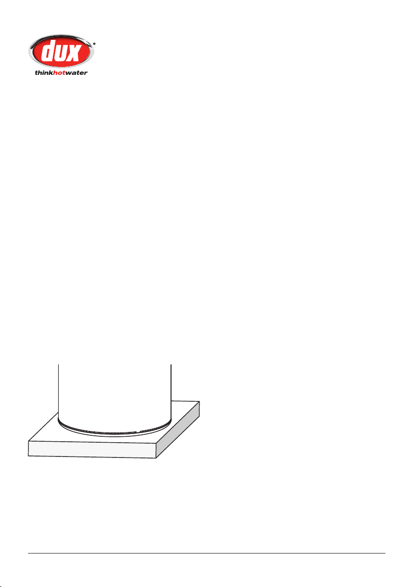
This water heater must be installed
on a re-proof base.
The water heater has a metal base so it
is recommended that a concrete plinth
be installed under the water heater to
protect the heater when subjected to
wet conditions.
A properly drained overow tray must
be used where property damage could
occur from water spillage. (See AS/
NZS3500.4 for further details.)
Note: Warranty does not cover
consequential damage due to heater
leakage.
Owner’s Manual – Electric Boosted Solar
3
Part No: H3100
Version: 10346D
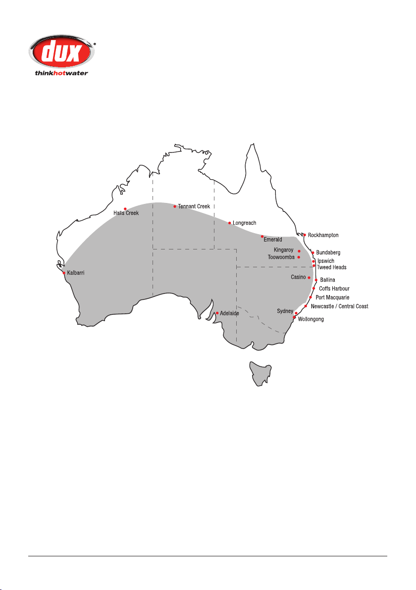
All locations highlighted in gray require an approved antifrost protection device to
maximise system performance. Call Dux Hot Water 1300 365 115 for further information.
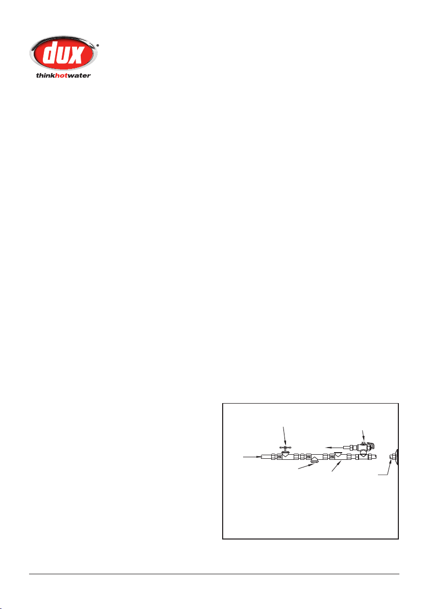
Installation Details
Frost Protection Installation Map
Owner’s Manual – Electric Boosted Solar
4
Part No: H3100
Version: 10346D
Union
Connection
Non-return
Valve
Line
Strainer
Cold Water
Inlet
Expansion
Valve*
Isolating Valve
(Spindle Vertical)
Plumbing Connections
This water heater must be installed
by a licensed tradesperson, and in
accordance with:
AS/NZS3500.4 “National Plumbing •
and Drainage Code Hot Water
Supply Systems – Acceptable
Solutions”.
Local authority regulations.•
Outside Australia and New Zealand, •
please refer to local plumbing and
building codes and regulations.
Notice to Victorian customers •
from the Victorian Plumbing
Industry Commission – this water
heater must be installed by a
licensed person as required by the
Victorian Building Act (1993). Only
a licensed person will give you a
compliance certicate, showing
that the work complies with all
the relevant Standards and only a
licensed person will have insurance
protecting their workmanship for 6
years.
This water heater is designed for direct
connection to water supply pressures of
no greater than:
250 Litre Model – 800kPa
315 Litre Model – 800kPa
400 Litre Model – 800kPa
Where the mains pressure can exceed
or uctuate beyond the pressure
shown above a pressure limiting device
(complying with AS1357) must be
tted in the cold water inlet supply.
This device must be installed after
the isolating valve and set below the
pressure shown above. Note during
periods of lower demand water pressure
may increase.
Caution: This water heater delivers
hot water at temperatures exceeding
50°C. Refer to AS/NZS3500 and local
regulations regarding the need for
additional temperature control of hot
water delivery.
Note: This water heater is not suitable
for pool heating.
Note: a combined isolating valve/nonreturn valve/line strainer may be used.
Expansion valve only required where local
regulations demand.

Owner’s Manual – Electric Boosted Solar
5
Part No: H3100
Version: 10346D
Plumbing Connections
Pressure & Temperature Relief
Valve
The Pressure & Temperature Relief Valve
is supplied loose with the water heater.
The valve rating is:
250 Litre Model – 1000kPa
315 Litre Model – 1000kPa
400 Litre Model – 1000kPa
The relief valve must be installed directly
into the top socket marked “RELIEF
VALVE”. The drain line from this valve
must run in a continuously downward
direction in a frost-free ambient position
with the discharge end left open to
atmosphere permanently. The Pressure
& Temperature Relief Valve supplied
with the water heater is not intended to
enable connection of the water heater to
supplementary energy sources such as
solar panels or slow combustion stoves
(refer AS/NZS 3500.4 for guidance on
these types of installations)
Warning: Operation of the relief valve
easing gear at least once every six (6)
months is recommended.
Danger: Failure to operate the relief
valve easing gear at least once every six
(6) months may result in problems with
the water heater
Important: The Pressure & Temperature
Relief Valve and the drain outlet pipe
must not be sealed or blocked. It is
normal for the valve to overow during
heating cycles.
Cold Water Connection
An approved isolating valve, non
return valve, line strainer (optional but
recommended), and union must be
tted between the supply main and the
RP¾/20 socket in the water heater.
All ttings must be approved by the
relevant Authority.
Note for S.A. and W.A.: It is a state
requirement that a pressure relief valve
be tted on the cold water supply line
between the non return valve and the
water heater
Hot Water Connection
The hot water line should be connected
to the RP¾/20 socket marked as
OUTLET. For the most economical
operation of the water heater, it is
recommended that all hot water lines
are insulated with high temperature, UV
resistant 13mm closed cell insulation.
Please check local regulations regarding
the use of hot water supply pipework
other than pipes made of copper.
Note: Plugs are supplied with the water
heater to plug off the ttings that are not
required. Ensure that a sealing material
is applied to the plugs to prevent
leaking.

Owner’s Manual – Electric Boosted Solar
6
Part No: H3100
Version: 10346D
Plumbing Connections
Safety Information
For safe performance this water heater
is tted with:
an over-temperature energy cut-out •
thermostat
a combination Pressure & •
Temperature Relief Valve.
These devices must not be tampered
with or removed. The water heater must
not be operated unless both of these
devices are tted and in working order.
The element cover should be removed
only by an electrician. The electrical
power supply switch must be turned
off and the fuse removed at the main
electrical supply switchboard before the
water heater electrical cover is removed.
The Pressure & Temperature Relief
Valve should be checked for adequate
performance or replaced at intervals
not exceeding 5 years, or less in areas
where local regulations apply. The lever
on the relief valve should be pulled to
operate the valve at least once every 6
months.
Temperature Protection
All solar water heaters have the ability
to produce hot water very quickly.
To reduce the risk of scald injury, it is
mandatory under the requirements of
Australian Standard AS/NZS3500.4.2
that a suitably approved temperature
control device be tted to the hot water
supply to outlets used primarily for
personal hygiene. This valve should be
checked at regular intervals to ensure its
operation and settings remain correct.
Note: All Dux solar water heaters are
supplied with tempering valves. Any
adjustment to the valve should be
made according to the manufacturer’s
recommendations.
Owner’s Manual – Electric Boosted Solar
7
Part No: H3100
Version: 10346D
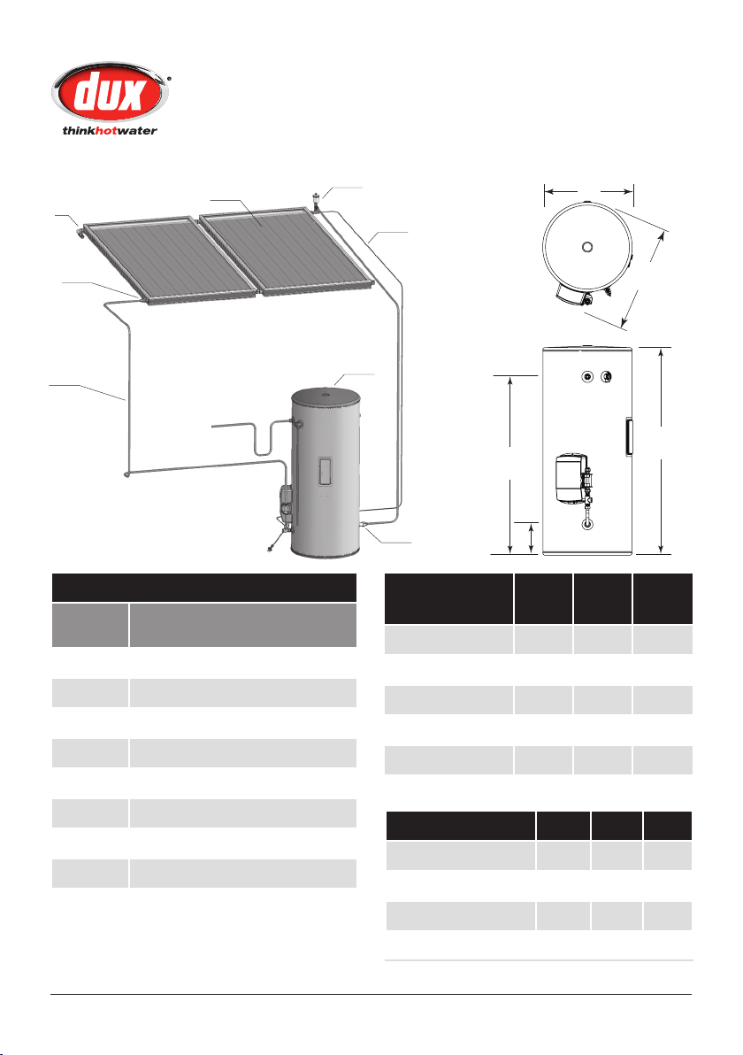
1
8
4
6
2
7
3
5
B
A
C
D
E
Specifications
System Components
Item
Description
Number
1 Solar Electric Tank Assy
2 Solar Collector Panel
3 Solar Collector Panel Fitting Kit
4 Solar Collector Sensor Lead
5 Tank – Collector Pipework
6 Air Bleed Valve
7 Ant-Frost Valve
8 Non Return Valve
Dimensions
250L 315L 400L
(mm)
Tank Height (A) 1444 1754 1703
Tank Diameter (B) 617 617 705
Tank Width (C) 718 718 806
Outlet (D) 1231 1541 1466
Inlet (E) 215 215 240
Specifications 250L 315L 400L
Storage Capacity (L) 259 324 416
Hot Water Delivery (L) 250 315 400
Net Weight Empty (kg) 90 105 120
Relief Valve Pressure (kPa) 1000 1000 1000

Owner’s Manual – Electric Boosted Solar
8
Part No: H3100
Version: 10346D
Installation – Collectors
Please ensure that sufcient roof space
is available to install the solar collectors
in the desired location.
Please allow the following roof space for
collector installation
2 collector panels – 3 meters wide • ×
3 meters high.
3 collector panels – 4.5 meters wide •
× 3 meters high
It is not advisable to install collectors
on roof spaces that are smaller than
described.
Solar Collector Installation
Note: Do not commence an installation
until you have satised yourself that all
Safety issues associated with working
on and lifting components onto a roof
have been addressed.
Important: All work associated with
the installation must comply with local
authority regulations including AS/
NZS 3500.4.2. Where these installation
instructions and local regulations are in
conict, local regulations must prevail.
Solar Collector Location Selection
There are ve major factors to consider in
selecting the solar collector location site.
For optimum performance, the solar 1.
collectors need to face the equator
(in Australia this is north). Due to the
high solar energy levels experienced
in Australia, installations on angles
of up to 45° away from north will
not have a major effect on the
annual solar output. Consequently
installations up to 45° away
from north are acceptable. If the
collectors are installed with an east
facing bias, the best solar input is
achieved in the morning and if there
is a west facing bias, the best solar
input is in the afternoon.
Careful site inspection is required to 2.
ensure the selected location is not
subjected to shading from adjacent
trees or buildings at any time of the
day, but particularly between 9am
and 3pm, the highest solar input
times. You must remember that
shadows are longer in winter than
in summer, so a site that is free of
shadows from adjacent objects in
summer may have some shadows
in winter.
 Loading...