

Page 1
This appliance shall be installed in accordance with:
• Manufacturer’s Installation Instructions
• Current AS/NZS 3000, AS/NZS 3500 & AS/NZS 5601
• Local Regulations and Municipal Building Codes including local OH&S requirements
This appliance must be installed, maintained and removed by an Authorised Person.
For continued safety of this appliance it must be installed operated and maintained
in accordance with the manufacturers instructions.
1 Dux Readyhot 11.007 V2 - 28/9/11
Page 2
DUX READYHOT (DEU-CUG1-AK) INSTALLATION MANUAL
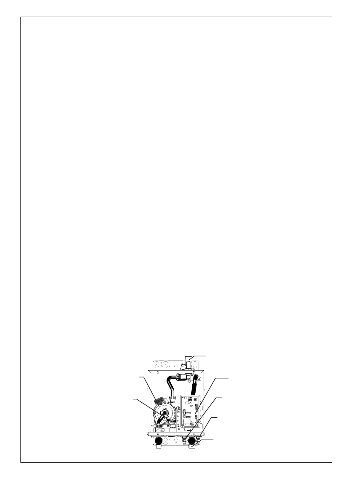
Circulating Pump
Heating Loop
Return Connection
Cold Water Inlet
Connection
Cold Water Outlet
Connection
PCB
Fig.1
Pump Bleed Valve
Cold Water Inlet
Bleed Valve
Power Lead
Control Lead
& Socket
You must install this appliance in accordance with these Instructions and all regulatory requirements which exist in
your area. Applicable publications may include:
• AS/NZS 5601 - Gas Installations
• AS/NZS 3500 - National Plumbing and Drainage
• AS/NZS 3000 - Wiring Rules
• Building Codes of Australia
NOTICE TO VICTORIAN CONSUMERS
This appliance must be installed by a person licensed with the Plumbing Industry Commission.
Only a licensed person will have insurance protecting their workmanship.
So make sure you use a licensed person to install this appliance and ask for your Compliance Certificate.
For further information contact the Plumbing Industry Commission on 1800 015 129.
THE READYHOT SYSTEM MUST BE MOUNTED ON A VERTICAL WALL OR STRUCTURE.
THE READYHOT SYSTEM CANNOT BE USED BY ITSELF OR WITH ANOTHER MANUFACTURERS WATER
HEATER OR WATER CONTROLLERS.
• The Dux Readyhot system is Certified and compatible only with the Dux Endurance water heaters.
• At least one Water Controller must be used in conjunction with the water heater and the Readyhot system.
Alternatively, if Water Controllers cannot be used a manual activation switch is available from electrical
wholesalers.
• The installation of the water heater and water controllers must be perfor med in a ccordance with the ' Operatio n /
Installation manual' supplied with the water heater.
• The Readyhot system is designed for domestic installations. However, it may be suitable for certain non
domestic installations. Contact Dux Manufacturing for more information.
READYHOT KIT CONTENTS (Fig.1)
The Dux Readyhot kit comprises an enclosure containing circulating pump, water connection s for cold water inlet,
cold water outlet and heating loop return, control wiring and printed circuit board. It is fitted with an electr ic po wer
cord with three pin plug suitable for connection to a 240 V 10 Amp GPO. It is also fitted with a control lead for
connection to the Dux Endurance water heater.
A Switch Harness (U268-605) is also provided for connection to a Manual Activation Switch (if required).
The Dux Readyhot kit does not include:
• 10 AMP GPO
• Heating loop flow and return pipework
• Gas and water isolating valves
• Control valves (non return valve, pressure limiting valve, expansion relief valve)
• Plumbing Connections between the Readyhot enclosure and Dux Endurance water heater and Dux water
Controllers
2 Dux Readyhot 11.007 V2 - 28/9/11
Page 3
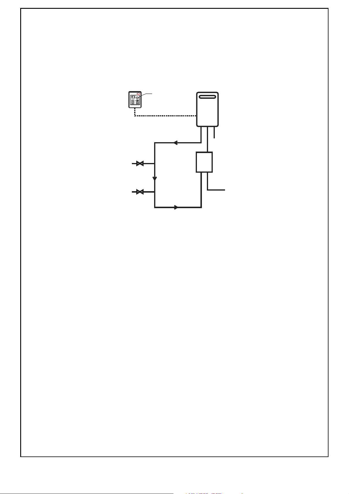
PRINCIPLE OF OPERATION (Fig. 2)
H
O
T
C
O
L
D
G
A
S
Cold Inlet Mains
Readyhot®
Module
Dux Endurance
Continuous
Flow Water Heater
Hot Water
Outlet
Hot Water
Outlet
Fig.2
Heating Loop Flow
Heating Loop Return
One or more
Controllers
Preheat Button
The "Readyhot" system heats the water in the pipework water connected between the water heater and the hot
water outlets before any outlets are opened using the 'flow and return' pipework principle. This results in water
savings and reduced waiting time for heated water delivery from the outlet when opened.
Traditional 'flow and return' systems usually keep the water in the pipework heated continuously. The Readyhot
system however, only heats the water before the outlet is opened. This results in significant energy savings
because water is not heated unnecessarily whilst retaining the benefits of traditional flow and return systems.
A schematic of the Readyhot system installed in conjunction with a Dux Endurance water heater and water
controller as shown in Fig.2 below.
The Readyhot system works as follows:
1. Before hot water is required, the user activates the Readyhot system by pressing the 'preheat' button on the
water controller or by pressing the Manual Activation Switch.
2. This activates the Readyhot system and the integral pump is switched on.
3. Water flows from the pump and passes through the water heater. This in turn activates the water heater
burner and water in the flow and return heating loop begins to heat.
4. When the Readyhot control mo dule se nses that the water in the full length of the flow and return heating loop
has been heated, the pump and water heater stop operating.
5. The user opens the desired hot water outlet. Preheated water will be delivered from the flow and return
heating loop to the outlet.
LOCATION (Fig. 3)
• Location and clearance requirements for the Dux water heaters are detailed in the Installation Instructions
supplied with it.
• The Readyhot module weighs 7.5 kg and the wall or structure on which it is to be mounted must be capable of
supporting the combined weight of the Readyhot unit, water heater and any associated pipework.
• Both the water heater and Readyhot module must be in an accessible location. Sufficient clearance shall allow
access to, and removal of, all serviceable components. Water heater and Readyhot modules must not be
mounted higher than 3.5 metres from the ground or floor level unless the customer can arrange permanen t and
safe access or can arrange another means of access, for example, by means of scissor or boom lifts.
• The Readyhot module is usually located below the Dux Endurance water heater. However, it can be mounted
anywhere within a 1.0 metre distance from the water heater (length of communication cable is one metre).
• An 10 Amp, AC240V weatherproof external earthed power point shall be provided adjacent to the Readyhot
module (the power cord is 1.5 metres long).
• Alternatively, the water heater and Readyhot module can share the same power point provided it is of the dual
outlet type.
• Double adaptors and extension leads must not be used.
• The power point must be kept clear of pipework connections, relief valve discharge points and the water heater
flue outlet.
3 Dux Readyhot 11.007 V2 - 28/9/11
Page 4
One or more
NOTE
Controllers
Dux
Water
Heater
Ensure location and clearances
around the water heater conform
with the installation instructions
supplied with the appliance
Hot Water
Branch Line
Hot Water
Branch Line
10
Power Lead
1.5 m
Power Lead
1.5 m
11
Readyhot®
Module
89
12
1
3
2
3
GAS
13
67 5 4
14
Hot Water
Branch Line
Furthest from
Water Heater
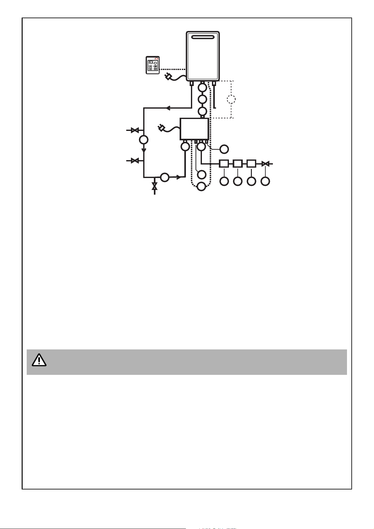
LEGEND TO FIG. 3
1. Water heater cold water inlet connection R¾” (20mm).
2. Readyhot module cold water outlet connection R¾” (20mm).
3. Copper tube R¾” (20mm), length approximately 300mm (maximum length 1000mm).
4. Isolating valve.
5. Non Return valve.
6. Pressure limiting valve, 500 kPa rating. OTHER RATINGS ARE UNSUITABLE!
7. Expansion control valve, 700 kPa rating. OTHER RATINGS ARE UNSUITABLE!
Ensure the drain line is installed in accordance with the requirements of AS/NZS 3500.
8. Readyhot module cold water inlet connection R ¾” (20mm).
9. Readyhot module heating return loo p inlet conn ection R½” (15mm).
10.Insulated heating loop 'Flow' pipework R¾” (20mm).
11.Insulated heating loop 'Return' pipework R¾” (20mm).
Cold Inlet
Mains
Fig.3
Total length of items 10 & 11 not to exceed 60 metres.
12.Pump bleed valve.
13.Cold water inlet bleed valve.
14.Readyhot water heater communication cable.
SERVICE CONNECTION POINTS
Positions and sizes of the connection points to the water heater and pipework are shown in Fig.3 and the
Dimensional drawings.
4 Dux Readyhot 11.007 V2 - 28/9/11
Page 5
VALVES (Fig. 3)
WARNING
WARNING
• Approved isolation and non return valves must be fitted to the cold water inlet.
• A combination isolating and non return valve may be used. Approved pressure limiting and expansion control
valves must also be fitted. A combination pressure limiting and expansion control valve may be used. The
pressure limiting valve must be rated at 500 kPa.
• The Expansion Control valve must be rated at 700 kPa. OTHER RATING COMBINATIONS ARE NOT
SUITABLE!
• Valves must not be connected directly to the Readyhot module or Dux Endurance water heater.
• It may be necessary to fit a temperature limiting device for delivery to areas used primarily for the purposes of
personal hygiene. Refer to the ‘Heated Water Delivery Temperature’ section of this document.
PIPEWORK (Fig. 3)
• All hot water pipework should be insulated to optimise performance and minimise energy wastage. This may
also be required by local regulations.
• The flow section of the pipework should be 20mm (¾") type B copper or equivalent. The return section of the
pipework should be 20mm (¾") type B copper or equivalent. Total combined length of the flow and return pipe
should not exceed 60 meters.
• The branch lines from the flow and return pipework to the hot water outlets should be sized in accordance with
AS/NZS 3500.
MOUNTING THE READYHOT MODULE (Fig. 3)
The Readyhot module is usually located below the Dux Endurance water heater. However, it can be mounted
anywhere within a 1.5 metre distance from the water heater. These instructions assume it is located below the
water heater.
Do not remove the front cover of the Readyhot or the water heater unless the power supply is
isolated. It is not necessary to remove the front cover of either appliances for the purposes of
mounting the Readyhot module.
1. Draw a line vertically down from the cold water inlet connection of the Dux Endurance water heater.
2. Mount the Readyhot module so the top edge of the enclosure is approximately 300 mm below the Dux
Endurance water heater with the water outlet connection of the Readyhot module in line with the water inlet
connection of the Dux Endurance water heater as shown in (Fig. 3).
3. Fasten the Readyhot module to the wall or supp orting st ructur e. The top bracket has a keyhole slot so that the
Readyhot module can be positioned by hanging it on one screw, then the other screws can be secured.
4. Connect a piece of 20mm (¾") type B copper or equivalent between the outlet of the Readyhot module and
the cold water inlet of the Dux Endurance water heater.
5. Connect the isolating, non return, pressure limiting a nd expansion contro l valves and an adequa tely size d cold
water supply pipe to the cold water inlet of the Readyhot module.
6. Plan the route of the 'flow and return' pipework to ensure the shortest distance between the pipework and the
hot water outlets.
7. Connect the 'flow and return' pipework between the hot water outlet of the Dux Endurance water heater and
the heating loop return connection on the Readyhot module. Insulate pipework. The 'return' section of the
pipework should be connected after the branch line furthest away from the water heater.
8. Install branch lines from the pipework to hot water outlets.
Install temperature limiting device in accordance with the ‘Heated Water Delivery Temperature’
section of this document.
COMMUNICATION CABLE
• Electronic signals are communicated between the Readyhot module and the Dux Endurance water heater via
the communications cable already connected to the Readyhot module.
• The communications cable is connected to the remote control connection terminals on the Dux Endurance
water heater in the same way as cables from the remote controller(s). Refer to the ‘WATER CONTROLLERS’
section of the ‘Operation / Installation Manual’ supplied with the Dux Endurance water heater for details.
5 Dux Readyhot 11.007 V2 - 28/9/11
Page 6
MANUAL ACTIVATION SWITCH
NOTE
50º C
appliance
KITCHEN
Water
Controller(s)
(at least one
DMC-91Q-2A)
LAUNDRY
BATHROOM
ENSUITE
H
O
T
C
O
L
D
G
A
S
Heating Loop Flow
Heating Loop Return
Cold Inlet
Mains
Readyhot®
Module
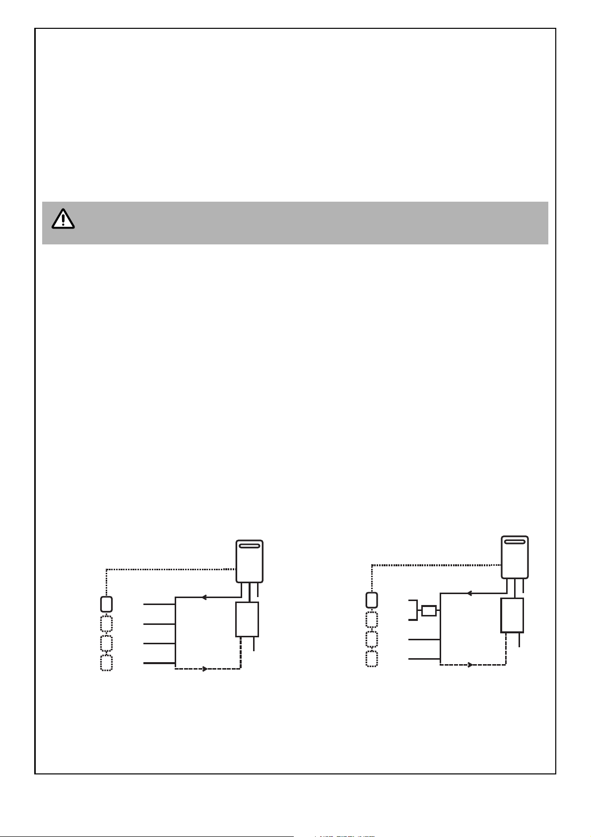
Fig.4. - 50°C Appliance
Minimum length of pipe from hot outlet
to nearest hot water tap 2 metres.
TLD
KITCHEN
Water
Controller(s)
(at least one
DMC-91Q-2A)
LAUNDRY
BATHROOM
ENSUITE
H
O
T
C
O
L
D
G
A
S
Heating Loop Flow
Heating Loop Return
Cold Inlet
Mains
Readyhot®
Module
Fig.5. - Not a 50°C Appliance.
Note: TLD = Temperature Limiting Device
• To obtain the full benefits of the water heater and Readyhot system, water controllers should be used. Howe ver
it is possible to use a manual activation switch to activate the Readyhot system if water controllers are not fitted.
Parts required:
• Two core sheathed (do uble insulated) flex with minimum cross sectional area of 0.5 mm
2
.
• Switch Harness (U268-605) this comes supplied with the Readyhot system.
• One or more manual activation switch(es). Suggested part is Clipsal 30PBL or equivalent.
Procedure:
• Install the manual activation switch(es) in the desired location in accordance with manufacturer instruction s.
Run the cable between the manual activation switches and the Readyhot system.
If more than one manual activation switch is used then the cables will need to be connected in
parallel before entering the Readyhot syst em. Only one cable can be connected to t he terminals
of the Readyhot system.
• Run the cable into the Readyhot enclosure using the same entry point as the communication cable fitted
between the Readyhot and the Dux Endurance Water heater.
• The switch harness is connection be tween the cable from the manual activation switch(es) and the Printed
Circuit Board (PCB) of the Readyhot. Connect the two wires from the manual activation switch ca ble to the Blue
and Black wires on the switch harness (polarity does not apply). If an LED indicator is used, connect the two
wires from the LED indicator to the Red and Black wires on the switch harness. Note: that the Orange wire on
the switch harness is not used.
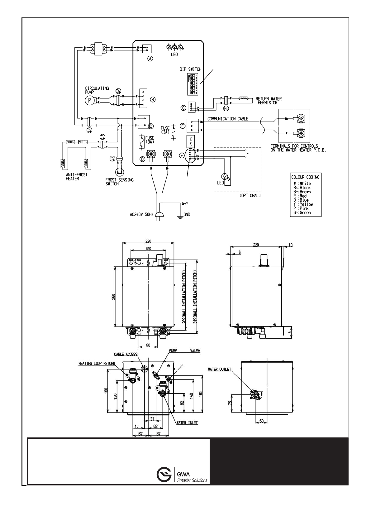
• Plug the switch harness into the PCB as shown in the Circuit Diagram on page 8.
WATER CONTROLLERS
• At least one controller must be fitted to enable activation of the Read yhot system. Up to three or four contro llers
can be fitted depending on water heater model. Refer to the 'WATER CONTROLLERS' section of the
'Installation Instructions' supplied with the Dux Endurance water heater and the Instruction sheet supplied with
the Dux water controller.
• Other types of Dux water controllers can be fitted but will not enable activation of the Readyhot system.
HEATED WATER DELIVERY TEMPERATURE
The maximum water temperature delivered at the hot water outlets is deter mined by the pre -set limit progra mmed
into the water heater. Local regulations and/or the requirements of AS/NZS 3500 must be considered regarding
the temperature limitations of hot water supplied to areas used pr imarily for pe rson al hyg ien e. The tem per atur e of
water to these areas may be limited to 50°C or less. If you are unsure about local regulations, contact your
regulating authority or Dux Manufacturing.
If the water heater is marked to state that it delivers
water not exceeding 50°C, local regulations may
permit installation without a Temperature Limiting
Device shown in Fig. 4
If the appliance is NOT marked to state that it delivers
water not exceeding 50°C, or your local regulations
require installation with a Temperatur e Lim iting D evice,
then the installation should be in accordance with Fig. 5.
6 Dux Readyhot 11.007 V2 - 28/9/11
Page 7
TESTING AND COMMISSIONING
CAUTION
12
13
NOTE
1. Ensure the power supply to the Readyhot unit is switched ‘off’.
2. Carry out steps 1-12 of the ‘Testing ' in the Commissioning section from the Operation / Installation manual
supplied with the water heater.
3. Inspect and clean the strainer located on the cold water inlet connection of the Readyhot module. This
procedure may need to be repeated to ensure the strainer remains clear, especially on new installations.
4. Turn ‘off’ the power supply to both the water heater and Readyhot units.
5. Open all available hot water taps, including the shower, again until water from all outlets is cold. Then close
the hot water taps.
Ensure building occupants do not have access to hot water outlets during this procedure.
6. Open the Readyhot module Pump and Cold Water inlet bleed valves items & of Fig. 3 (actual
position of 'bleed valves' is shown on dimensional drawing) until all air pockets are released and a steady
stream of water is discharged.
7. Activate the power supply to both the water heater and Readyhot units.
8. If water controllers are fitted: Press the ‘on/off’ button on the water control panel. The ‘on’ indicator next to
the transfer button will glow when the control panel has been switched ‘on’. Then press the ‘preheat’ button on
the control panel. The ‘preheat’ indicator next to the preheat button will glow indicating that the preheat system
has been activated. Then adjust the temperature to the hottest setting by pressing the ‘hotter’ button until the
temperature displayed on the control panel cannot be increased any further .
If a manual activation switch is fitted: Press the switch once.
With the Readyhot unit now activated via the water cont roller or man ual activation switch, the pump should
start running immediately afterwards which is indicated by the left LED on the Readyhot PCB glowing
green continuously. Check that this is the case. If the left LED on the Readyhot PCB does not glow green
the pump has not started. In this case there is probab ly an incor rect or missing wir ing connection between
water controllers or manual activation switch and the water heater or Readyhot unit. Check all wiring and
connections between these items.
If the pump activates as required, shortly afterwards the water heater should turn on also. Wait two
minutes. This will allow the water in the pipework to be warmed. If the water heater does not turn on re
check electrical connections and installation.
9. Open the heated water outlet furthest away from the water heater. The water should become war m in a matter
of seconds.
The waiting time for heated water delivery will vary depending on the size and layout of the
branch line.
10. Inspect and clean the strainer located on the heating return loop inlet connection of the Readyhot module.
This procedure may need to be repeated to ensure the strainer remains clear, especially on new installations.
11.Confirm the temperature delivered at the outlet with a suitable thermometer or digital temperature indicator. It
should not exceed the temperature displayed on the water controller or the pre-set limit programmed into the
printed circuit boards of either the Readyhot module or water heater.
12.After testing is completed, explain to the householder the functions and operation of the water heater, Water
controller(s) and the Readyhot module. Explain to the househ older that so me temperatur e fluctuations may be
experienced some of the time as a result of installing Readyhot.
13.Ensure the customer record section of the 'Operation / Installation manual' is filled in and that the booklet is
handed to the customer.
14.The preheat function is cancelled 5 minutes after activation and the ‘preheat’ indicator will go out. This is to
conserve energy. To reactivate, simply repeat steps 7-10 above
7 Dux Readyhot 11.007 V2 - 28/9/11
Page 8
CIRCUIT DIAGRAM
Default position of all dipswitches is 'OFF' (to the left)
MANUAL
ACTIVATION
SWITCH
Location for Switch
Harness (manual
activation switch)
TRANSFORMER
BLEED
COLDWATERINLET
BLEEDVALVE
Head Office
Lackey Road
Moss Vale NSW 2577
AUSTRALIA
Tel: 1300 365 115 (Australia)
Tel: 0800 729 389 (New Zealand)
Manufacturing Limited
ABN 19 077 879 844
DUX
Internet: www.dux.com.au
For advice, repairs and service, call:
1300 365 115 (Australia)
0800 729 389 (New Zealand)
DIMENSIONS DIAGRAM
8 Dux Readyhot 11.007 V2 - 28/9/11
 Loading...