

Page 1
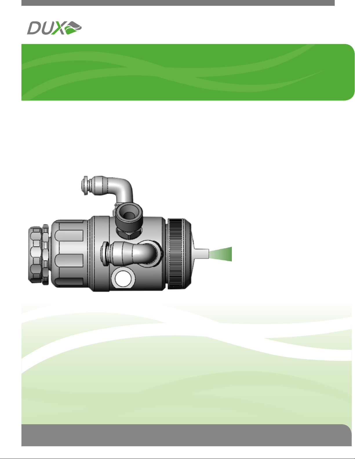
DUX Automatic
Product
Manual
P.O. Box 1314 Seahurst WA 98062 | Phone 888.389.2732 | Fax 888.876.1233 | www.DuxTechnologiesInc.com
Page 2

AUTOMATIC
The DUX Automatic
INSPIRED BY FORMULA THREE RACE CAR
ENGINES.
After more than 5 years of research and
development, DUX has reinvented th e spr a y gun
from the inside out. By incorporating our
patented airflow technology, originally used in
Formula Three race car engines, we’ve
developed the most innovative breakthrough in
spray gun technology in nearly 80 years.
For the first time, finishers can spray nearly any
type of fluid, onto nearly any surface with a
single gun – while reducing coatings waste and
improving finish quality.
TECHNOLOGY THAT’S EASY TO USE AND
EASY ON US.
Patent Information
The design and technology forming the basis of
this product is the confidential information of DUX
Technologies Inc.,aWashington corporation.
The relevant US Patent Numbers are: US
6,793,157; US 6,425,533, and U.S. 7,004,404.
DUX Technologies Inc. may have additional
patents, patent applications, trademarks,
copyrights, or other intellectual property rights
covering subject matter in this document.
Except as expressly provided in any written
license agreement from DUX Technologies
Inc., this document does not grant you any
license to or rights in any such patents,
trademarks, copyrights, or other
intellectual property.
The DUX Automatic spray gun uses a patented
technology to reduce overspray and booth “fog”.
Less paint in the air means more paint on the
target and a corresponding decrease in booth
filter replacement and hazardous waste disposal
potentially cutting the operating cost of a
fees,
paint line by 50%. Since the DUX Automatic
achieves atomization with a lower volume of air,
you may also see a reduction in compressor
energy consumption.
© 2006 DUX Technologies Inc. All
rights
reserved.
DUX, DUX Technologies, DUX Automatic
are either registered trademarks or
trademarks of DUX AREA Inc. in the
United States and/or other countries.
Part No. 510003
Printed in the United States of America
For customer service call 888.389.2732
Page 1
Page 3
Table of Contents
AUTOMATIC
Warning
Safety Information
Installation
Fittings ...........................................................................................Page 4
Setup.............................................................................................. Page 4
Connections................................................................................... Page 4
Operation
Fluid Control Knob......................................................................... Page 5
Fan Control Adjustment.................................................................Page 5
Troubleshooting
Maintenance
Fluid Needle Removal ...................................................................Page 7
....................................................................................................Page 3
s
....................................................................................Page 3
.................................................................................................Page 4
Mounting........................................................................................Page 4
...................................................................................................Page 5
Automatic.................................................................................. Page 5
Manual...................................................................…………….Page 5
Operating the Spray Gun............................................................... Page 5
.......................................................................................Page 6
............................................................................................. Page 7
Lubrication .................................................................................... Page 7
Fluid Tip Removal.......................................................................... Page 8
Fluid Packing Adjustment.............................................................. Page 8
Fluid Packing Replacement...........................................................Page 9
Removal . ................................................................................. Page 10
Replacement ............................................................................ Page 11
Cleaning
Flushing................................................................................................. Page 12
Exploded View
Replacement Parts List
Technical Data/ Specifications
Notes Section
Warranty
For customer service call 888.389.2732
..................................................................................................... Page 12
General Cleaning .......................................................................... Page 12
.......................................................................................... Page 13
............................................................................................. Page 15
.................................................................................................... Page 16
............................................................................. Page 13
................................................................. Page 14
Page 2
Page 4
AUTOMATIC
!
WARNING
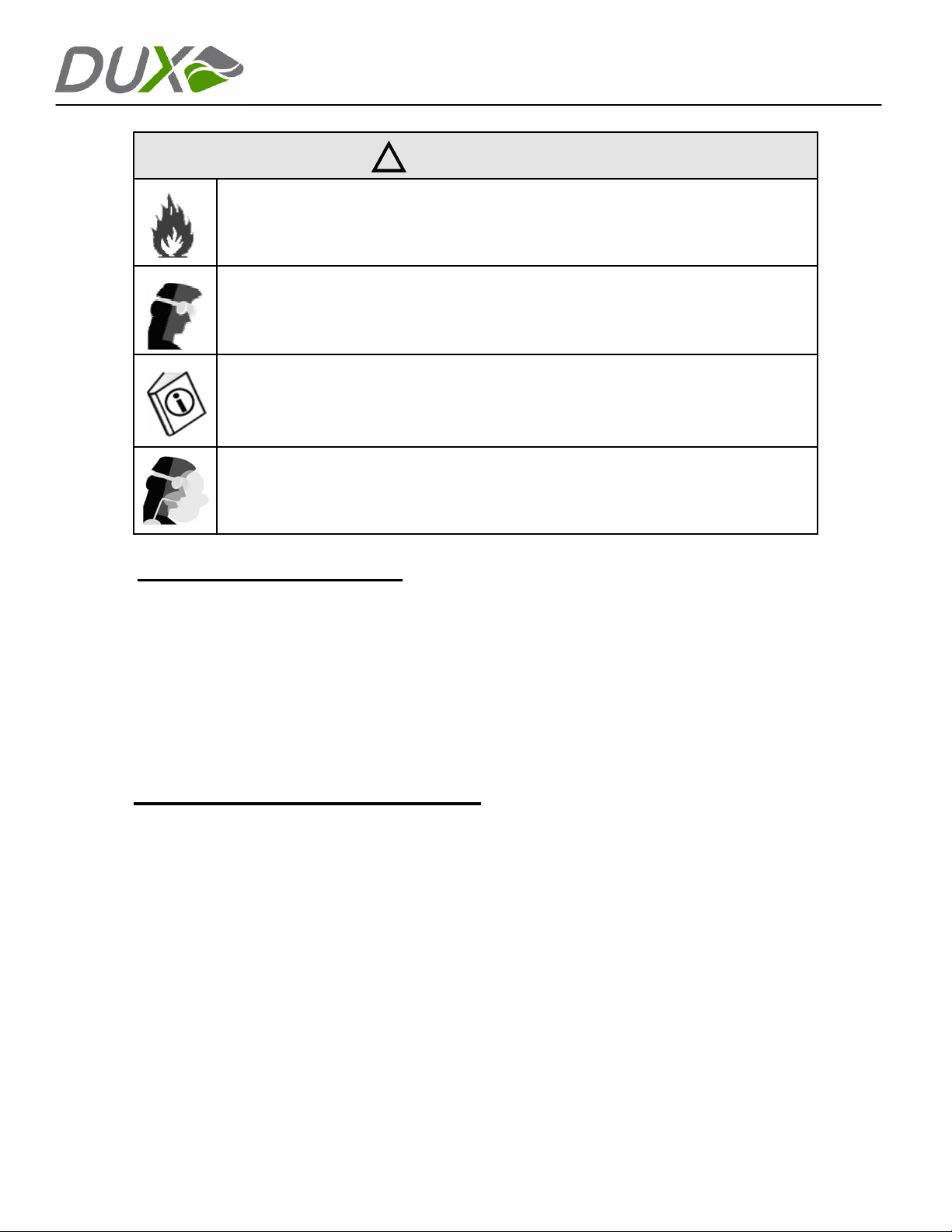
Coatings and solvents may be extremely flammable or combustible. Always use the equipment
in a properly ventilated area. Smoking must never be permitted in the spraying area. Make sure
that all ignition sources are well out of range and always keep fire extinguishing equipment in
the spraying area.
Some solvents may cause eye injury during operation and/or while cleaning the equipment.
Always wear eye protection when working with the equipment.
Always read the MSDS supplied by the material manufacturer.
Some coatings and solvents may be harmful if there is contact
Always make sure to read the MSDS supplied by the material manufacturer. Always use the
equipment in a properly ventilated area. If there is a chance of inhalation or contact with skin,
use protective gear such as a respirator and/or proper clothing as suggested by the MSDS.
Required Maintenance
• Clean equipment after each use
Lubrica
•
Do not s
•
Ensure prop
•
mishandling of the spray gun is not covered by warranty
• Ensure air a
• Do not a
Problems resulting from
•
te spray gun before each use and/or after every
ubmerge spray gun in solv
er handling of the gun at all times - damage due to dropping or
nd fluid hoses are properly connected
pply air or fluid pressures above the maximum published inlet pressure
any of the above-mentioned situations will jeopardize warranty
ent
cleaning
Automatic Safety Information
• Use the equipment only for its intended purpose
Do not p
•
• Do not pla
•
Inspec
Shut off all air sources a
•
Use fluid
•
Chec
•
Do not al
•
Do not u
•
•
ways refer to the owner’s manual for proper operating instru
Al
Comply
•
Read all instruction man
•
Al
ways read the MSDS supplied by the material manufacturer
•
• Do not exceed 75 psi for air and fluid; 50 psi for triggering air
oint spray gun at any part of body
ce hand or fingers over spray
t for physical damage or loose fittings befo
nd remove coating supply to spray gun before serv
s and solvents that are compatible with equipment wetted part
k equipm
with all applicable safety
ent often
ter or modify
se with improperly operating
equipment
regulations
uals, tags, and labels before operating the equipm
tip
re use
equipment
with the skin or if inhaled.
s
icing
s
ctions
ent
For customer service call 888.389.2732
Page 3
Page 5
Quick Reference Guide
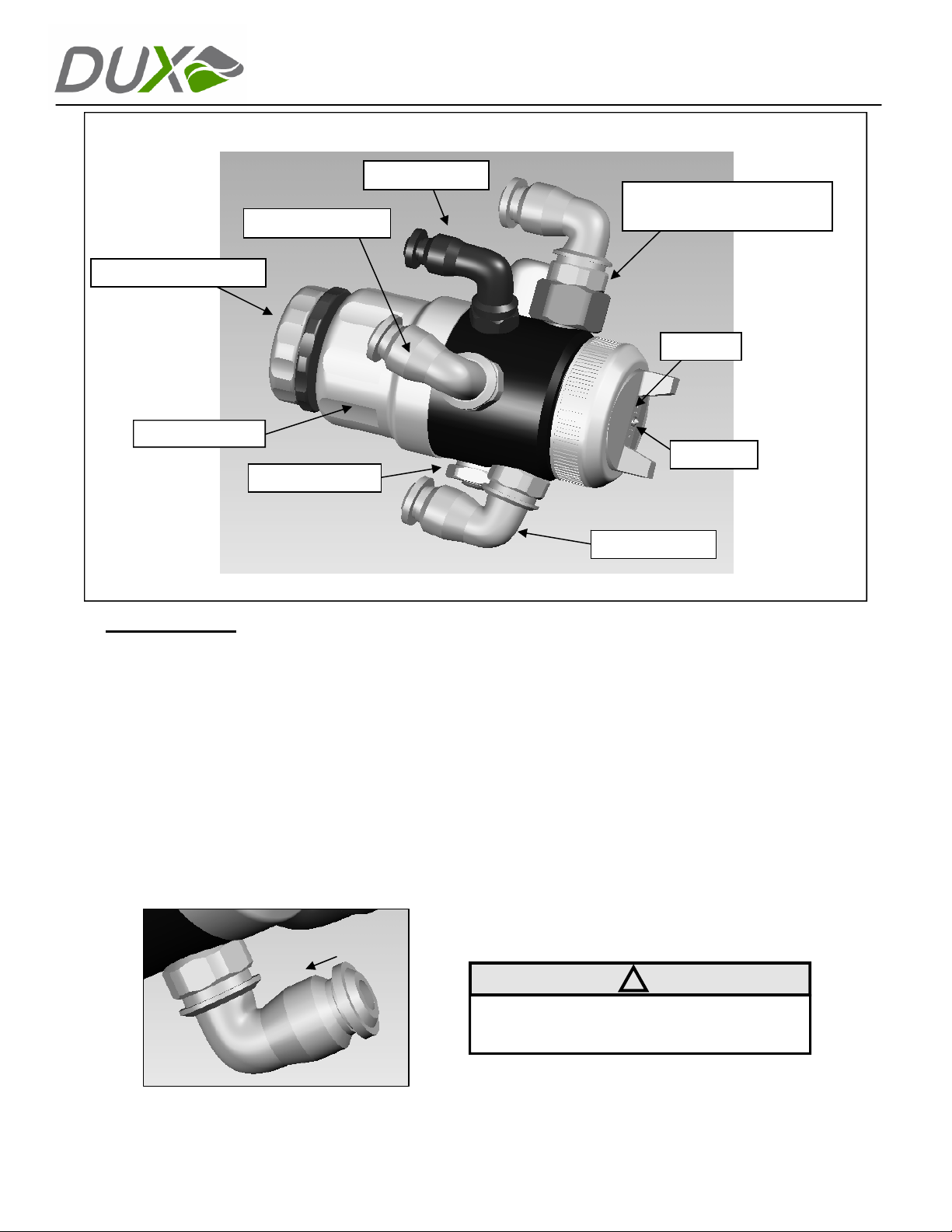
Triggering Air
Fluid Connection
Fluid Control Knob
Trigger Housing
Mounting bolt
AUTOMATIC
Fan Control
(Automatic model shown)*
Air Cap
Fluid Tip
Figure 1
Installation
Mounting
When using the supplied mounting bolt, install the
spray gun onto a mounting rod 1/2” and tighten
using the hex screw. The mounting bolt can be
attached to either side of the spray gun by simply
unscrewing the bolt and reversing position.
Fittings
The DUX Automatic spray gun uses push-lock
style fittings as standard equipment. To attach the
hoses, insert one end of the hose into the fitting
until it’s locked it into place. To release the lock,
push the plastic locking ring toward the fitting
while removing the hose (See Figure 2).
Atomizing Air
*See figure 4 on
page 5 for
fan control
Setup
Prior to setting up air and fluid hose(s) plea
note:
• All hoses must be cut clean and straight
without deformity for prope
Use an air filter to ensure a clean, dry
•
air supply.
•
Trigg
ering air, atomizing
control air
sup
plied and regulated sepa
The fluid ho
•
shut-off valve, and a filter prior to use.
Conn
ections
Attach the triggering air, atomizing air, and fluid
hoses to the corresponding connections on the
spray gun. When applicable also attach the fan
control air.
NOTE: When using fittings other than the
supplied push-lock style fittings, installation may
differ.
(when applicable) must
se must have a regul
!
r fit.
air and fan
rately.
manu
se
be
ator,
al
Figure 2
For customer service call 888.389.2732
Page 4
Page 6
Operation Guide
AUTOMATIC
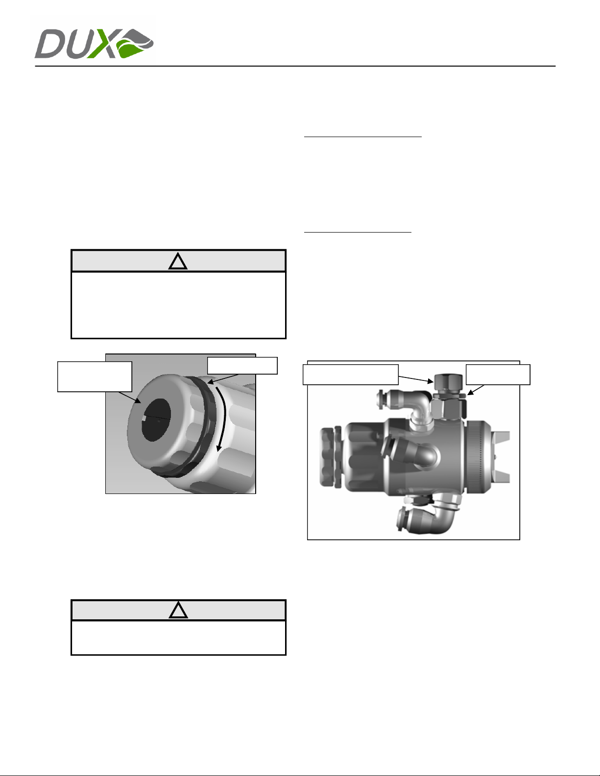
Fluid Control Knob
The fluid control knob is located at the rear of the
spray gun (See Figure 3). To increase the fluid
flow, turn the fluid control knob
counter-clockwise. Conversely, turn the fluid
control knob clockwise to reduce the fluid flow.
Once the desired settings have been achieved,
turn the fluid control locking ring clockwise to
lock the fluid control knob into place (See Figure
3).
!
NOTE: If the fluid control knob stops offering
resistance, maximum needle travel has been
reached. If the flow rate is insufficient, increase
the fluid tip and needle size.
Fluid Control
Knob
Locking Ring
Autom
for automatic fan adjustment have an additional
push-lock fitting for fan control. Air is externally
supplied to the air horns of the air cap to control the
size and shape of the spray pattern. The more air
pressure applied, the larger the fan pattern. When
the optimal results are achieved, record the input
pressure settings for simple future setups.
Manual Fan Adjustment:
manual fan adjustment have a fan control valve
with a locking ring (See Figure 4). Pattern shaping
air is obtained from the main air chamber of the
spray gun. With the fan control valve in the fully
closed position (i.e. no threads showing), a
minimum spray pattern size is achieved. Pattern
size increases as the adjustment knob is rotated
counter-clockwise, allowing more air to be directed
to the air horns. When the optimal results are
achieved, turn the locking ring clockwise to lock
valve in place.
Manual Fan Control
atic Fan Adjustment
Spray guns configured for
: Spray guns configured
Locking Ring
Figure 3
Fan Control Adjustment
The fan control adjustment is located on the side
of the spray gun near the air cap. This
adjustment controls the amount of air delivered
to the horns of the air cap for spray pattern
shaping (See Figure 4).
!
NOTE: Applying excessive air to the air cap will
result in a split pattern.
The DUX Automatic spray gun features two
methods of fan control adjustment:
For customer service call 888 DUX AREA (888 389 2732) Page 5
Figure 4
Operating the Automatic Spray Gun
1.
Turn on the regulated triggerin
minimum of 35 psi inpu
Turn on the regulated fluid
2.
Trigger spray gun and ob
3.
4.
Turn the fluid control knob counter-clockwise
until desired flow rate is achieved.
5.
Turn on the regulated atomizing air at the
source of supply.
Adjust the atomizing air pressure
6.
desired fluid atomization is achieved
Adjust fluid flow as necessary to achiev
7.
desi
red result
s.
t pressure.
line.
serve fluid flow.
g air at a
.
e
until
Page 7
AUTOMATIC
Troubleshooting
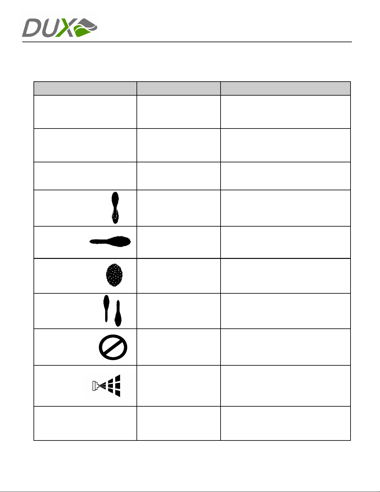
Problem Cause Solution
1.
Remove triggering assembly
2.
Coating leakage
out of tip of spray gun
Coating leakage out of rear of
spray gun or drain hole
Needle packing is too tight
Needle packing is too loose
Insert screwdriver into rear of spra
3.
Turn fluid seal nut counter-clockwise 1/4 turn (refer
to page 9 for pac
Lubricate needle
4.
1.
Remove triggering assembly
2.
Insert screwdriver into rear of spra
3.
Turn fluid seal nut clockwise 1/4 turn (refer to page
9 for packing adjustment)
Lubricate needle
4.
king adjustment)
and reinstall
and reinstall
y gun
y gun
Spray gun does not trigger
Split pattern
Heavy right or
left side pattern
“Orange peel” or
Heavy pattern
Heavy top or bottom
pattern
Will not spray
Spray gun
sputtering
1. Insufficient triggering air
2. Piston binding
1. Air pressure too high
2. Fluid flow too lo
Dirty or damaged air
cap/holes
1. Air pressure is too low
Spray gun is too
2.
w
orking
3.
Fluid flow is too
1. Air cap dirty or damaged
2. Fluid tip dirty or da
1. Insufficient air pressure
2. Insufficient fluid flow
3.
Fluid too heavy for current
setup
1. Damaged fluid tip
2. Loose fluid tip
3.
Dried material in fluid tip/
needle
4.
Fluid source empty/low
5. Needle packing too loose
w
close to
surface
high
maged
1. Increase triggering air pr
Note: Do
2. Remove triggering assembly. Remove trigger pi
and lubricate o-ring. Reinstall
1. Reduce atomizing air pressure
2.
Turn fluid control knob counter-clockwise
Note: if fluid flow is still insufficient after adjusti
replace fluid tip with next largest si
Clean air cap
Note: Do not use metal tools to clean air cap
Note: If problem persists after cleaning, replace air cap
1. Increase atomizing air pressure
2.
Ensure proper distance from surf
is achieved, normally 6-10” from
3.
Adjust fluid control knob clockw
decrease fluid flow
1. Clean air cap
Note: Do
2. Clean fluid tip
Note: If problem
air cap or fluid tip
Check atomizing air and triggering air pr
1.
and increase if necessar
2.
Adjust fluid control knob counter-clockwise to
increase fluid flow
3.
Thin coating and/or change fluid tip to next largest
size
Remove and inspect for damage
1.
2. Ensure fluid tip is tight
3.
Flush with solven
4.
Check coating and refill if necessary
See solution: (coating leakage out of rear of gun
5.
not exceed 50 psi
not use metal tools to
essure
ston
ng,
ze
ace
surface
ise to
clean air cap
persists after cleaning replace
essures
y
t
)
Spray pattern starved or dry
For customer service call 888.389.2732
1. Air pressure too high
2. Fluid adjustment too low
Spray too far from
3.
surface
working
1. Reduce atomizing air pressure
2.
Adjust fluid control knob counter-clockw
desired results are achieved
Ensure proper distance from surface is achieved,
3.
normall
y 6-
10”
Page 6
ise until
Page 8
Maintenance Guide
The DUX Automatic spray gun is a precision
tool that delivers superior finishing results and
cost savings with each use. Optimal results
require good handling and maintenance
processes.
Daily cleaning, lubrication, and proper
aintenance are required to maintain
m
the warranty coverage.
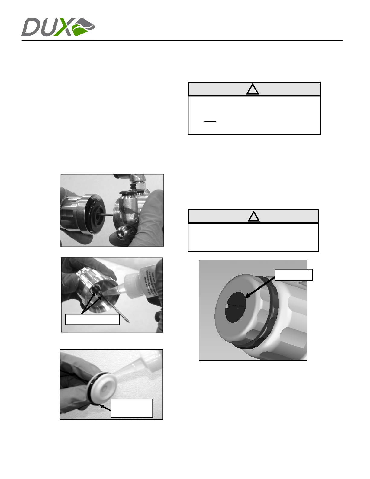
Lubrication
sure the quality and longevity of the
To en
DUX spray gun, it must be lubricated before
every use and after every cleaning. Follow
the diagram below to ensure proper
lubrication (Use DUX lube—part # 310206).
AUTOMATIC
Fluid Needle
NOTE: Due to the self-cleaning nature of the
fluid tip and needle combination; it is imperative
that both
increasing or decreasing the fluid tip size.
To replace or change the fluid needle:
Ensure both fluid and air are depressuri
1.
Unscrew the fluid control
2.
cou
it, along
trigger housing
Unscrew the spring cap from the
3.
adjustment knob (See Figure 8)
Removal
!
parts are changed together when
knob by turning
nter-clockwise and completely remo
with the fluid needle, from the
.
.
zed.
ving
fluid
Figure 5: Unscrew trigger housing
Lubrication areas
Figure 6: Lubricate thick part of needle
and needle o-rings
Trigger
Piston O-Ring
!
CAUTION: The needle spring is under
pressure and is retained by this cap. It may
spring free when the cap is removed.
Spring Cap
Figure 8
4.
Remove the needle spring
Remove and replace the n
5.
Lubricate needle as required and reinstal
6.
needl
e assembly.
.
eedle.
l
Figure 7: Lubricate the trigger piston
For customer service call 888.389.2732
Page 7
Page 9
Maintenance (continued)
AUTOMATIC
Fluid Tip Remo
NOTE: Due to the self-cleaning nature of the
fluid tip and needle combination; it is imperative that both
increasing or decreasing the fluid tip size.
To replace or change the fluid tips:
1.
Ensure the spray gun is depressurized.
Remove the air cap retaining ring an
2.
cap.
Using the DUX 10mm fluid tip driver, remove
3.
the fluid tip and inspect the threads for wear
or contamin
Install a new fluid tip and tighten using the
4.
DUX 10
IMPORTANT: Do not over-tighten. Use a
maximum of 18 INCH pounds of torque or a
half turn past hand tight. The precision
machining of the DUX Automatic makes the
use of a gasket unnecessary.
IMPORTANT: To maintain the precise fit and
seal between the fluid tip and the stainless
steel fluid barrel, paint must not be allowed to
dry on the threads. The threads of both the
fluid barrel and tip must be thoroughly cleaned
after each use.
val
!
parts are changed together when
d air
ation.
mm fluid tip driver.
!
!
IMPORTANT: Some coating leakage out of
the fluid tip may indicate an adjustment of the
packing is needed. This is not an indication of
the spray gun failing.
Always ensure the spray gun is depressurized
before making adjustments.
Fluid Packing Adjustm
The fluid packing in all DUX spray guns is set
to a pre-determined specification during
assembly. Therefore, depending on the type of
material being sprayed, it is possible that the
packing will need adjustment upon start-up or
after some amount of spraying.
Fluid leakage at the front of the spray gun is
an indication that the fluid needle is not
seating properly in the fluid tip. This may be
caused by dried material in the tip, or if the
fluid packing is too tight. If the packing is set
too tightly for a particular material, the needle
will not to fully seat in the fluid tip and will
require adjustment.
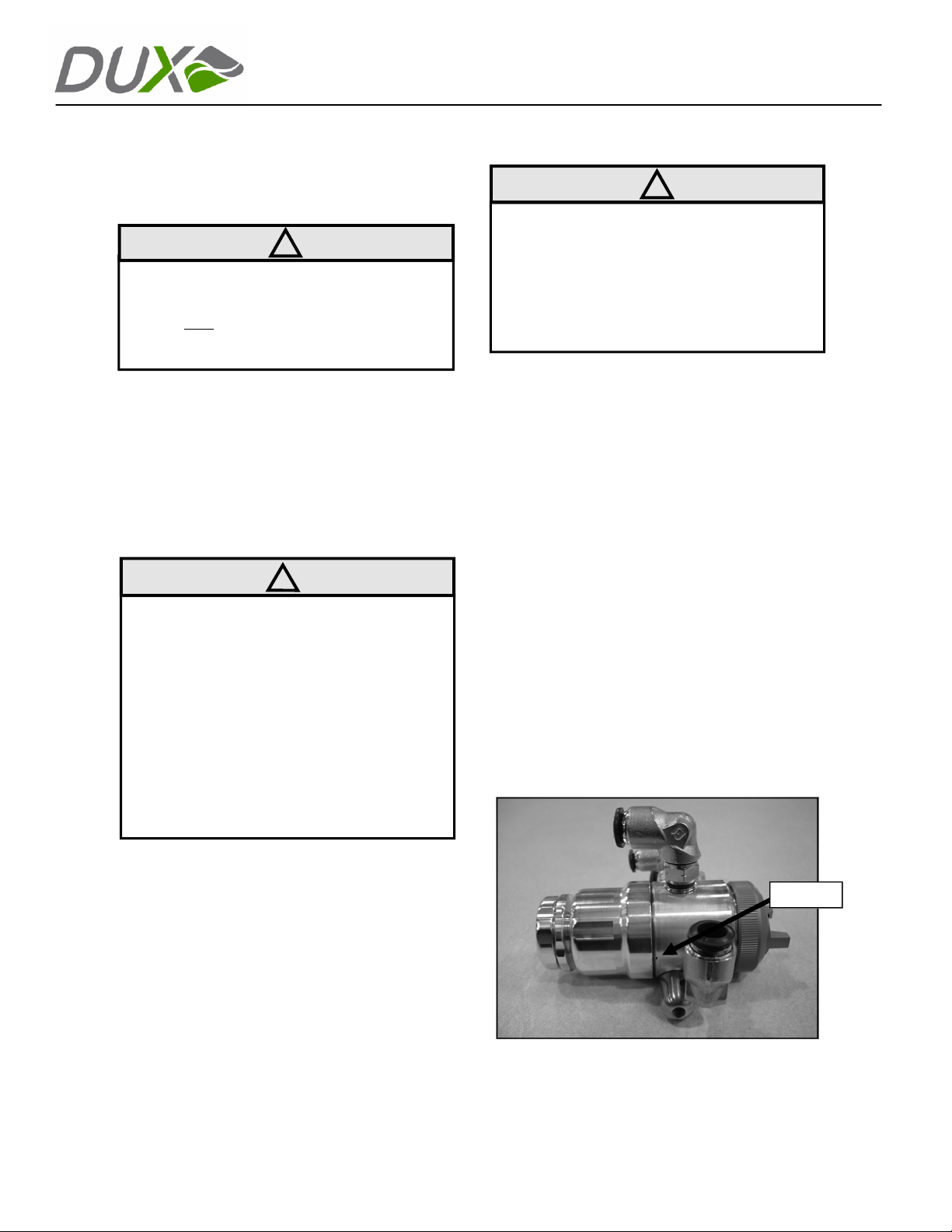
The DUX Automatic features a leak indicator
in the form of a pin hole located above the
mounting bolt (See Figure 9). Fluid leakage at
this pin hole indicates that the fluid packing is
too loose and will need tightening.
ent
5.
Replace air cap and air cap retaining ring
For customer service call 888.389.2732
.
Pin hole
Figure 9
Page 8
Page 10
AUTOMATIC
Maintenance
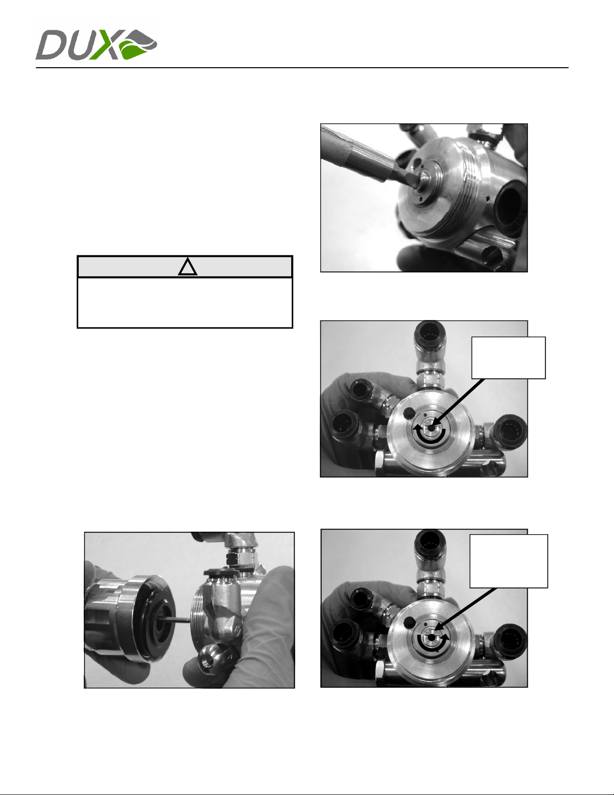
To adju
1.
2.
3. Ins
st the packing:
Ensure the spray gun is depressurized.
Unscrew the trigger housi
body by tu
compl
etely removing it, along with the
needl
e and trigger piston (See Figure 10
CAUTION: The needle spring is under
pressure and is retained by this cap. It may
spring free when the cap is removed.
ert a thin, flat-blade sc
rea
r of the main spray gun body (See Fi
nd turn the fluid seal nut 1/4
11) a
clo
ckwise to tighten or counter-clockwis
loosen (See Figure 12 & 13).
rning counter-clockwise
(continued)
ng from the main
and
fluid
).
!
rewdriver into the
gure
turn
e to
Figure 11
Fluid Seal Nut.
Turn clockwise
to tighten
Reinstall the trigger housing with the fl
4.
needl
e and trigger piston onto the sp
gun body.
Pressurize the spray gun a
5.
6.
Rep
eat if necessary.
Figure 10
nd test.
uid
ray
Figure 12
Fluid Seal Nut.
Turn counterclockwise to
loosen
Figure 13
For customer service call 888.389.2732
Page 9
Page 11
Maintenance (continued)
AUTOMATIC
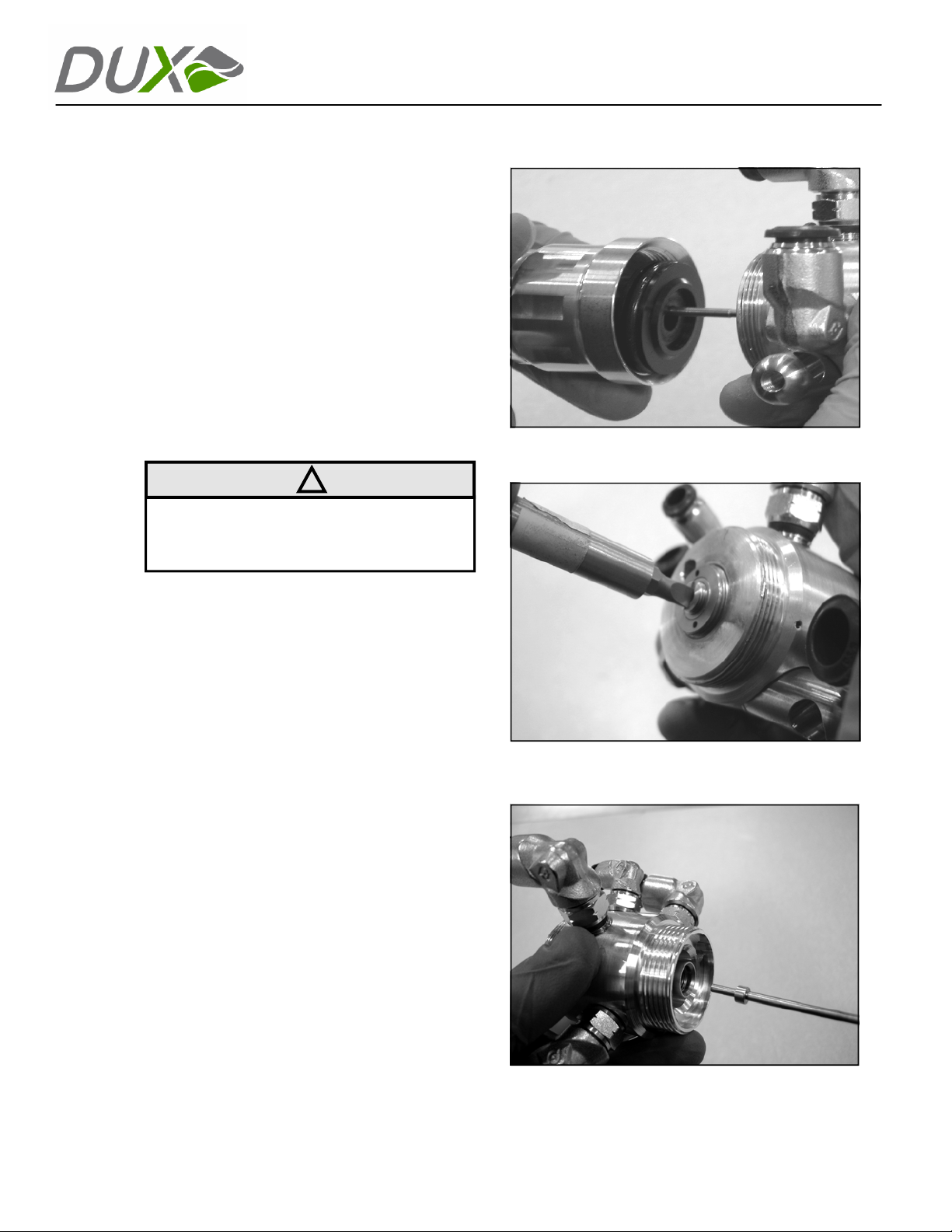
Fluid Packing Replac
Removal
Ensure the spray gun is depressurized.
1.
2.
Remove the air cap retaining ring air ca
Remove the fluid tip using the DUX 10
3.
tip driver.
Unscrew the trigger housing and fully re
4.
along
from the main
Using a flat-blade screwdriver, remo
5.
packin
counter-clockwise (See Figure 15
Insert the DUX fluid packing tool into the
6.
with the fluid needle and trigge
CAUTION: The needle spring is under
pressure and is retained by this cap. It may
spring free when the cap is removed.
g adjustment screw by turning
ement
spray gun body (See Figu
!
).
p.
mm fluid
move it,
r piston
re 14).
ve the
Figure 14
stainless steel fluid barrel at the fron
spray gun.
7.
Remove the fluid packing components by
pushing the DUX fluid packing tool fully toward
the rear of the spray gun, forcing the packing
assembly out. Be sure to remove all packing
contents from the fluid tube (See Figure
Inspect and clean the packing cavity inside the
8.
spray gun. If necessary, use a spray gun
cleaning brush to remove excess debris
For customer service call 888.389.2732
t of the
Figure 15
16).
.
Figure 16
Page 10
Page 12
Maintenance (continued)
AUTOMATIC
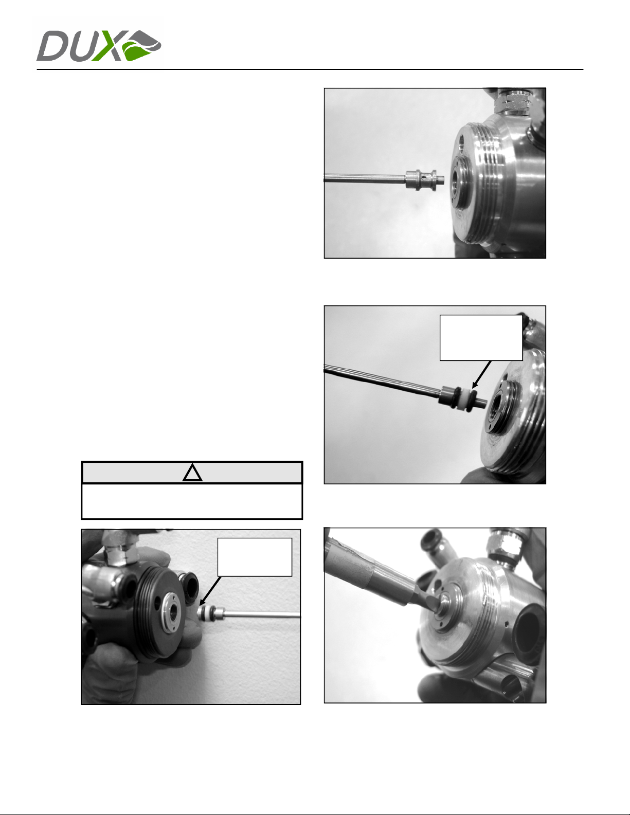
Replacemen
1. Inspect the fluid packing adjustment screw
for wear.
2.
Place one fluid seal, two o-rings, and the fluid
seal front at the tip of the fluid packing tool
and gently slide the tool into the fluid tube
(See Figure 17). Firmly seat the packing.
3. Next, using the same technique, insert the
brass fluid seal spacer (See Figure 18).
4. Again, using the same technique, place the
second fluid seal and two o-rings into the
fluid tube (See Figure 19).
5. Start the packing adjustment nut into the
body by han
until it is flush with its stainless steel housing
(See Figure 20).
6. Lubricate the fluid needle as indicated in
figure 6 and reinstall the trigger housing,
along with the fluid needle and trigger
piston.
7. Replace the fluid tip using the DUX 10mm
fluid tip driver.
t
d. Tighten the fluid packi
ng nut
Figure 18
Lubricate fluid
seal and o-rings
before inserting
!
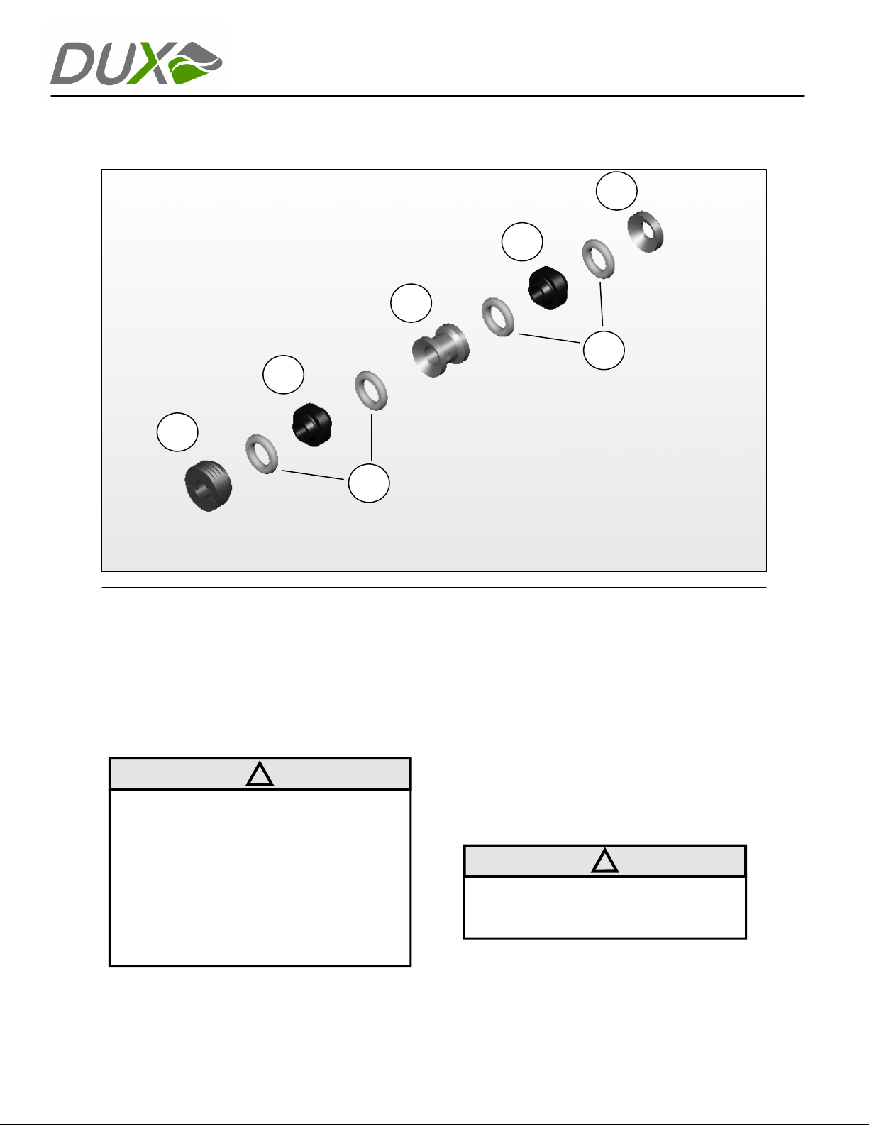
NOTE: See page 12 to view order of packing
components.
Brass fluid
seal base
Figure 17 Figure 20
For customer service call 888.389.2732
Figure 19
Page 11
Page 13
E
AUTOMATIC
A
B
D
C
B
C
Cleaning Guide
Cleaning the
Daily cleaning, lubrication, and proper
maintenance are required to maintain the
warranty coverage (See page 7 for lubrication
and maintenance instructions).
CAUTION:
DUX Automatic
!
The DUX Automatic spray gun can easily be
cleaned in the following ways:
Flushing
1. Ensure the spray gun is depressurized.
2.
3. Pressurize the spray gun.
4. Thoroughly clean the spray gun and fluid
General Cleaning
• Remove the air cap and clean it with a soft
• Do not fully submerge the spray gun in
solvents or cleaning solutions.
• Do not clean air cap holes with metal tools
as it could effect the spray pattern.
• The DUX Automatic may be cleaned in a
spray gun washer.
• Use a cleaning solvent that is compatible.
•
Fluid Seal Base
B. Fluid Seal
C.
Fluid Seal O-Ring
Fluid Seal Sp
D.
E. Fluid Seal Nut
Replace the material being sprayed with
cleaning solvent.
hose by triggering repeatedly until clean.
bristle brush.
!
NOTE: Do not clean air cap holes with
metal tools as it could effect the spray
pattern.
ng the DUX 10mm fluid tip driver, remove
Usi
the fluid tip and inspect threads for wear or
contamination. Clean with solvent.
acer
For customer service call 888.389.2732
Page 12
Page 14
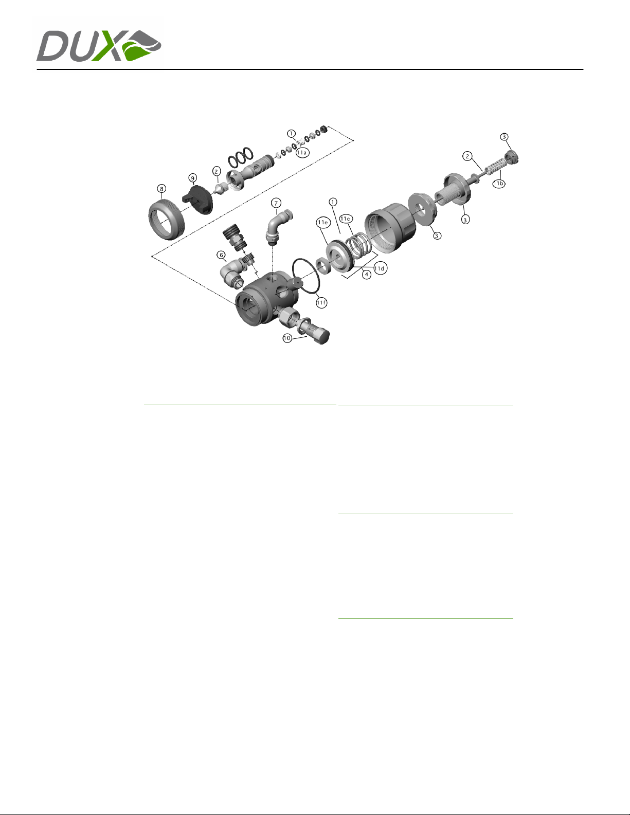
Exploded View
AUTOMATIC
No. Part Description
1.2.310129
310325
310326
310327
310328
310329
310330
310331
310332
310333
3. 310115
4. 310134
5. 310167
6. 410326
7. 410325
8. 9.310157
410465
410466
410467
10. 310112
Fluid N eedle Pack ing Kit
SC Tip/N eedle Set (.6mm)
SC Tip/N eedle Set (.8mm)
SC Tip/N eedle Set (1.0mm)
SC Tip/N eedle Set (1.2mm)
SC Tip/N eedle Set (1.4mm)
SC Tip/N eedle Set (1.6mm)
SC Tip/N eedle Set (1.8mm)
SC Tip/N eedle Set (2.0mm)
SC Tip/N eedle Set (2.2mm)
Fluid Control Assembly
Trigger Ki t
Mount ing Bolt Kit
3/8” Push to Conn ect Swivel Fit ting
1/4” Push to Con nect Swivel Fi tting
Air Ca p Ring
Air Ca p, A0, Stain less Steel
Air Ca p, A1, Stain less Steel
Air Ca p, A2, Stainless Ste el
Fan Cont rol Valve w/lock ing ring
No. Part Description
11. 310172 Wearabl e Parts Rep lacement Ki t
Accessories
310201
310472
310175
310176
310223
310233
310235
Tools
310174
310173
410606
410522
310310
Includes:
11a (1) flui d needle pac king kit
11b (1) need le spring
11c (1) trig ger sprin g
11d (1) trig ger piston o -ring-30mm
11e (1) trigger ho using o-r ing-36mm
11f (1)trigger housing
PTFE Ma gnaLube (.75oz)
PTFE Ma gbelube 10PK (.75oz)
Exter ior Cleani ng Brush
Fluid Tube Cleaning Brush
Air Ca p Tester, A0, Stainle ss Steel
Air Ca p Tester, A1, Stainle ss Steel
Air Ca p Tester, A2, Stain less Steel
Dux 10mm Flui d Tip Driver
Dux Pac king Tool
Dux Mul ti-Tool Wren ch
Packi ng Driver
Packing Pressure Gauge
For customer service call 888.389.2732
Page 13
Page 15
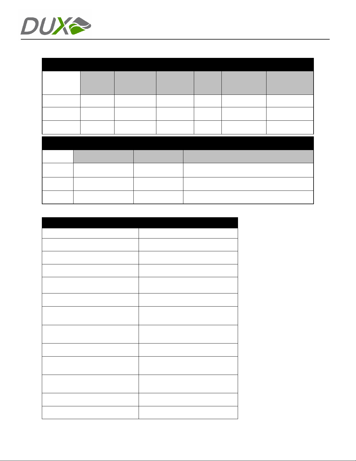
Technical Data
Fluid Tip and Air Cap Selection Chart
AUTOMATIC
Material Type
Light 0.6 - 1.2 12.5 oz./min. A1 8.6 scfm 16.0"
Medium 1.2 - 1.6 12.0 oz./min. A1 8.6 scfm 14.0"
Heavy 1.6 - 1.8 12.0 oz./min. A1 8.6 scfm 14.0"
Fluid Viscosity Definitions
Light Up to 18 seconds Up to 20 cP
Medium 18 to 28 seconds 20 - 64 cP Conve ntional solids urethanes, acrylics, alkyds
Heavy 28+ seconds 60+ cP High solids urethanes, acrylics, alkyds
Specifications
Body Material Anodized Aluminum
Fluid Passage Material Stainless Steel
Air Cap Material Anodized Aluminum
Weight* 1.4 lbs
Maximum Atomizing Air Inlet Pressure**
Maximum Inlet Fluid Pressure 75psi
Atomizing Air Inlet***
Fluid Tip
#2 Zahn Cup Centipose (cP) Examples
Fluid Pressure
3 psi
4 psi
5 psi
Quick Disconnect/Push Lock Swivel
Fluid Flow
(oz/min)
10.7 psi
Fitting for 3/8” Diameter Tubing
Air Cap
Lacquers, stains, varnishes, conventional primers,
wash primers, water based acrylic basecoats
Air Consumption
(10psi inlet
pressure)
*Weight includes fluid/air
supply fittings and mounting
hardware
**When operated to
maintain HVLP compliance
(10 psi or less at air cap)
*** When the atomizing air
supplied to the DUX
Automatic gun is on,
atomizing air will constantly
flow through the gun and
out the air cap independent
of triggering
Max Usable Fan
Pattern at 9"
Spray Distance
Fluid Inlet
Feed Type Automatic
Fan Control
Fan Control Inlet (Automatic
Adjustment)
Fan Control Inlet Pressure 2-20 ps
Triggering Pressure Minimum 35 psi
or customer service call 888.389.2732
F
Quick Disconnect/Push Lock Swivel
Fitting for 3/8” Diameter Tubing
Manual adjustment or Automatic
adjustment (external air supply)
Quick Disconnect/Push Lock Swivel
Fitting for 1/4” Diameter Tubing
i
Page 14
Page 16

AUTOMATIC
__________________________________________________________________________
____
____________________________________________________________________________________________
____________________________________________________________________________________________
____________________________________________________________________________________________
____________________________________________________________________________________________
____________________________________________________________________________________________
____________________________________________________________________________________________
____________________________________________________________________________________________
____________________________________________________________________________________________
____________________________________________________________________________________________
____________________________________________________________________________________________
____________________________________________________________________________________________
____________________________________________________________________________________________
____________________________________________________________________________________________
____________________________________________________________________________________________
____________________________________________________________________________________________
____________________________________________________________________________________________
____________________________________________________________________________________________
For customer service call 888.389.2732
Page 15
Page 17

AUTOMATIC
DUX Standard Warranty
DUX TECHNOLOGIES INC. WARRANTS TO CUSTOMER THAT ALL DUX TECHNOLOGIES INC.
PRODUCTS (A) ARE FREE FROM DEFECTS IN MATERIALS OR WORKMANSHIP AND (B) MEET
ALL APPLICABLE DUX TECHNOLOGIES INC. SPECIFICATIONS.
WILL REMAIN IN EFFECT FOR ONE YEAR FROM THE DATE OF SALE. IN THE EVENT A
PRODUCT FAILS TO MEET THE FOREGOING WARRANTY, CUSTOMER SHALL NOTIFY DUX
TECHNOLGOES INC. AND REQUEST A RE-TURN MATERIAL AUTHORIZATION NUMBER (RMA)
BEFORE RETURNING THE PRODUCT PUR-SUANT TO DUX TECHNOLOGIES INC.’S
INSTRUCTIONS. DUX TECHNOLOGIES INC. WILL REPAIR OR REPLACE, AT DUX
TECHNOLOGIES INC.’s OPTION, ANY PRODUCT THAT FAILS TO MEET THE FOREGOING
WARRANTY. IF DUX TECHNOLOGIES INC. DETERMINES THAT REPAIR OR REPLACEMENT IS
NOT REASONABLE, DUX TECHNOLOGIES INC. MAY INSTEAD REFUND CUSTOMER’S
PURCHASE PRICE FOR THE NONCONFORM-ING PRODUCT. THE ABOVE WARRANTY IS IN
LIEU OF ALL OTHER WARRANTIES, EXPRESS OR IMPLIED. DUX TECHNOLOGIES INC.
NEITHER ASSUMES NOR AUTHORIZES ANY OTHER PERSON TO ASSUME ANY OTHER
LIABILITIES IN CONNECTION WITH THE SALE OR USE OF ANY PROD-UCT. EXCEPT FOR
THOSE WARRANTIES EXPLICITLY DESCRIBED IN THIS PARAGRAPH, DUX TECHNOLOGIES
INC. DISCLAIMS ALL OTHER WARRANTIES, EXPRESS OR IMPLIED, INCLUDING ANY
WARRANTY OF MERCHANTABILITY OR FITNESS FOR A PARTICULAR PURPOSE.
THE FOREGOING WARRANTY
Please note that your Automatic Spray Gun was
shipped with the following contents:
• DUX Automatic Gun
• Quick Reference Guide, PTFE Grease Lubricant, and DUX 10mm Nut
Driver
If anything is missing, or you would like to order additional parts, please
contact:
DUX Customer Service
DUX TECHNOLOGIES, INC.
P.O. BOX 1314
Seahurst, WA 98062
Tel: 888.389.2732
Fax: 866.876.1233
Website: www.DuxTechnologiesInc.com
Email: [email protected]
Page 16
 Loading...