

Dux AiroHeat D2FH00000C Owner's Manual
Owner’s Manual
Heat Pump Water Heater
Model: D2FH00000C
Installation Details
Commissioning Checklist
Owner’s Information (warranty)
For advice, repairs and service, call:
1300 365 115 (Australia)
0800 729 389 (New Zealand)
Specications and materials may change without notice.
Effective for Airoheat
Part No: H3023
Version: 10155G
®
Water Heaters manufactured and sold after 1st June 2006.

Owner’s Manual – Airoheat
®
Part No: H3023
Version: 10155G
Contents
Welcome To Dux Hot Water 1
Installation Details 2
Plumbing Connections 5
Electrical Connection 8
Installation Checklist 10
Commissioning The System 11
Operational Diagrams 12
Commissioning Check List 13
Owner’s Instructions 14
Troubleshooting 17
System Maintenance 19
Safety Information 20
Service Information 21
Warranty 22
Warranty Card 25
Owner’s Manual – Airoheat
®
1
Part No: H3023
Version: 10155G
Welcome To Dux Hot Water
Your decision to purchase a Dux Hot
Water system will reward you for many
years to come.
Since 1915, the Dux range has seen
continuous research and development,
resulting in many breakthroughs in the
efciency, reliability and longevity of hot
water systems.
Dux water heaters are manufactured
in Australia in a state-of-the-art facility,
using a Quality Endorsed Company
production system.
This is your assurance that you have
purchased the highest quality water
heater available, one that will provide
continuous hot water for all your needs
– safely, economically, and for many
years to come.
To be upfront about it, we want Dux to
be your brand of choice. So you can
depend on us to provide more than just
a hot water system.
Go with Dux and you’ll have a
dependable, economical, efcient hot
water system designed to perform well,
year after year. And that’s a promise.
You can rely on Dux products and
choose them with condence. We’ll
make sure you have the information, the
quality and the innovation you’re looking
for, including the latest energy-saving
alternatives. If you should ever have a
problem – and we’ll bet you won’t –
you’ll nd that we’re easy to get hold of,
friendly to talk to and quick to act. Our
service is all about providing anything
you need as soon as you need it.

Owner’s Manual – Airoheat
®
2
Part No: H3023
Version: 10155G
Installation Details
This water heater must be installed
by a licensed tradesperson, and in
accordance with:
AS/NZS3500.4.2 “National •
Plumbing and Drainage Code Hot
Water Supply Systems – Acceptable
Solutions” .
Local authority regulations.•
Outside Australia and New Zealand, •
please refer to local plumbing and
building codes and regulations.
Notice to Victorian customers •
from the Victorian Plumbing
Industry Commission – this water
heater must be installed by a
licensed person as required by the
Victorian Building Act (1993). Only
a licensed person will give you a
compliance certicate, showing
that the work complies with all
the relevant Standards and only a
licensed person will have insurance
protecting their workmanship for 6
years.
Note: This water heater and heat pump
components are not suitable for pool
heating.
All warranty is voided if the unit is laid on
its side for storage or transport. It must
be stored and transported in a near
vertical position at all times, there are no
exceptions.
This water heater is designed for direct
connection to water supply pressures of
no greater than:
250 Litre Model – 800kPa
Where the mains pressure can exceed
or uctuate beyond the pressure
shown above a pressure limiting device
(complying with AS1357) must be
tted in the cold water inlet supply.
This device must be installed after
the isolating valve and set below the
pressure shown above. Note during
periods of lower demand water pressure
may increase.
Caution: This water heater delivers
hot water at temperatures exceeding
50°C. Refer to AS/NZS3500 and local
regulations regarding the need for
additional temperature control of hot
water delivery.
Owner’s Manual – Airoheat
®
3
Part No: H3023
Version: 10155G
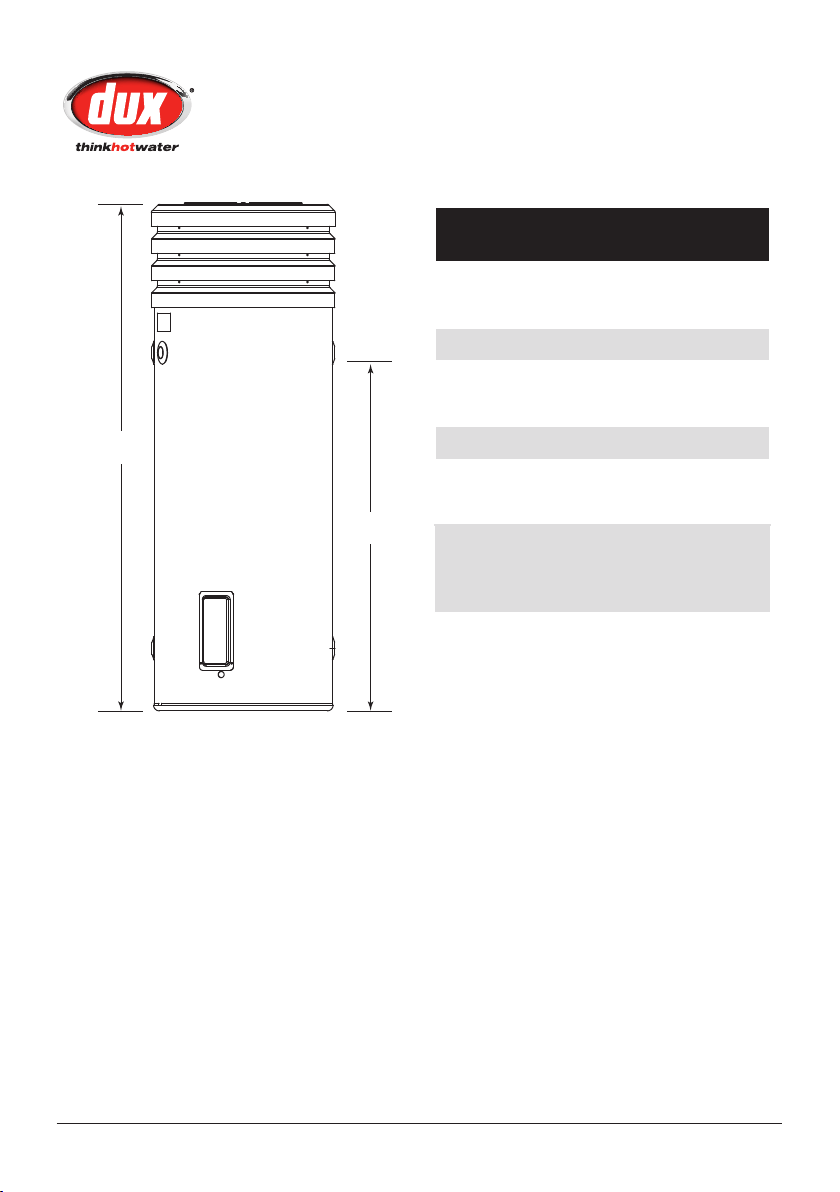
Airoheat
P
r
e
f
e
r
r
e
d
i
n
s
t
a
l
l
a
t
i
o
n
p
o
s
i
t
i
o
n
700mm
150mm
150mm
Installation Details
Location
The water heater should be located as
close as possible to the most frequently
used hot water outlet. Ensure that the
data plate is clearly visible and provide
adequate access for service to the
element, thermostat, relief valve and
anode.
Note: All models are equipped with 2
sacricial anodes, accessible through
the top cover. Allow 50% of the height
of the water heater for clearance above
to replace the anodes.
The water heater has a plastic base
which is resistant to water damage but
it is recommended that a concrete plinth
be installed under the water heater
to protect the heater when subjected
to wet conditions and to allow free
circulation of air. A properly drained
overow tray must be used where
property damage could occur from
water spillage. (See AS/NZS3500.4.2 for
further details.)
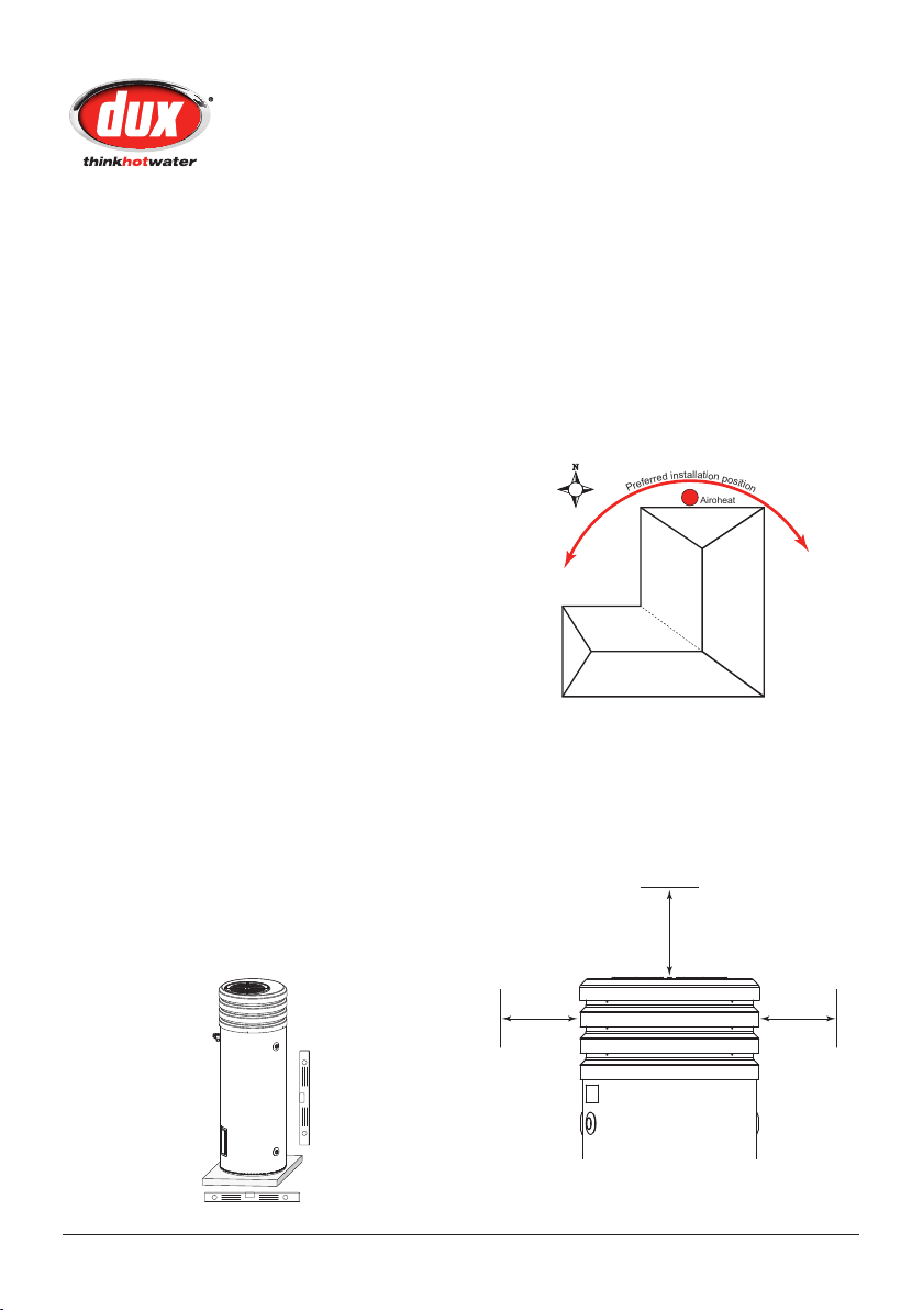
Preferred Location
If possible the location selected for the
heat pump should be on the warm side
of the home.
The selected location must have free
ambient air ow to prevent cooler
discharged air being drawn back into
the heat pump.
Allow sufcient clear space so as not
to impede this air ow. Allow 700 mm
clearance above the Airoheat and allow
150mm clearance to either side of the
Airoheat as a general rule.
Note: The warranty does not cover
consequential damage due to leakage
of the water heater.
Owner’s Manual – Airoheat
®
4
Part No: H3023
Version: 10155G
Dux Manufacturing Limited a division of GWA International Limited
No further
Installation Details
Noise Considerations
The selected location must consider
noise impact on living areas, especially
bedrooms, inside the house. Although
the running noise level is very low (51
dB(A)) it can be expected that the heat
pump will run during the night.
The installer can assist in choosing the
appropriate location for the Airoheat.
Air Flow
Ensure the unit is placed in an area were
debris such as leaves and paper etc, will
not collect and block the air outlet on
the top of the unit.
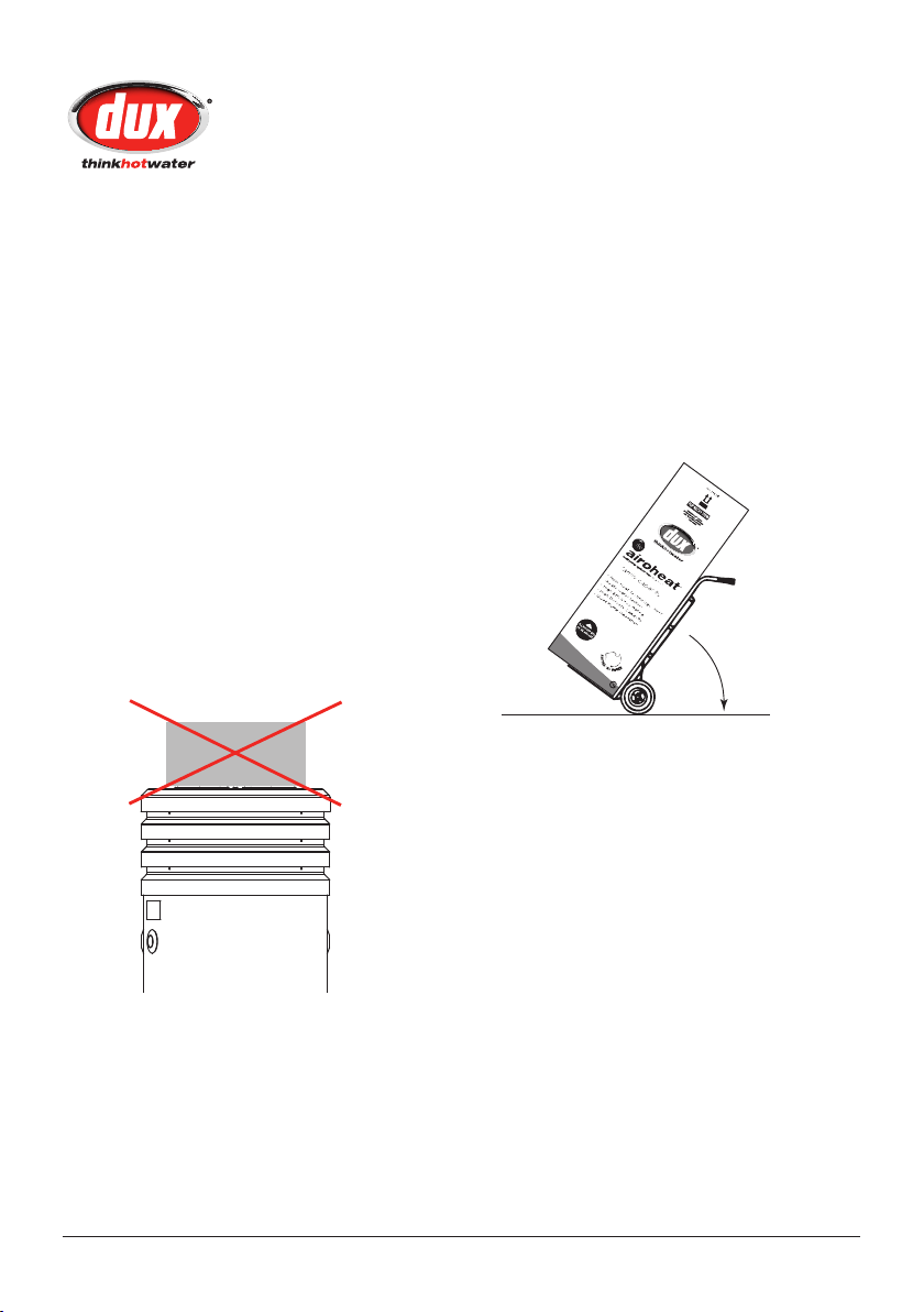
Important: Do not put any objects on
top of the Airoheat unit!
Transportation
Ensure the Airoheat is always stored and
transported in an upright position.
Note: All warranty is voided if the unit is
laid on its side for storage or transport.
It must be stored and transported in a
near vertical position at all times, there
are no exceptions.
Owner’s Manual – Airoheat
®
5
Part No: H3023
Version: 10155G
A
B
Plumbing Connections
Storage Tank Installation
Install and connect the storage tank to
the household water reticulation system
as per local plumbing regulations and
codes.
Installation Dimensions
Table (mm) – 250 Litre
Tank Height (A) 1755
Overall Diameter 632
Height (from base of heater)
Hot Water Outlets (B) 1231
Cold Water Inlets 215
Minimum louver clearances
Sides 150
Top 700
All measurements approximate only.
Specifications and material are subject to change
without notice.
Cold Water Connection
An approved isolating valve, nonreturn valve, line strainer (optional but
recommended), and union must be
tted between the supply main and the
RP¾/20 socket in the water heater.
All ttings must be approved by the
relevant installation Authority.
Install a condensation drain line in a
continuous fall away from the heat
pump to a safe and legal point of
discharge. Usually this would be a
garden bed or similar location.
Owner’s Manual – Airoheat
®
6
Part No: H3023
Version: 10155G
Plumbing Connections
Note for S.A. and W.A.: It is a state
requirement that a pressure relief valve
be tted on the cold water supply line
between the non-return valve and the
water heater.
Hot Water Connection
The hot water line should be connected
to the RP¾/20 socket as shown on
the Installation diagram. For the most
economical operation of the water
heater, it is recommended that all hot
water lines are insulated with high
temperature, UV resistant 13mm
closed cell insulation. Please check
local regulations regarding the use of
hot water supply pipe work that are not
made of copper.
Pressure & Temperature Relief
Valve
The Pressure & Temperature Relief Valve
is supplied loose with the water heater.
The valve rating is:
250L Model – 1000kPa
The relief valve must be installed directly
into the top socket marked “RELIEF
VALVE”. The drain line from this valve must
run in a continuously downward direction
with the discharge end left permanently
open to atmosphere. The Pressure &
Temperature Relief Valve supplied with
the water heater is not intended to
enable connection of the water heater to
supplementary energy sources such as
solar panels or slow combustion stoves
(refer AS/NZS 3500.4.2 for guidance on
these types of installations)
Warning: A separate drain line must be
run for this relief valve. It is not permitted
to couple drain lines from relief valves
into a single common drain line.
Water Quality
Your Dux water heater has been
manufactured to suit all water conditions
in “All Water Areas” present in Australia.
Please note that harsh water supplies
can have a detrimental effect on a water
heater and its life expectancy. If you are
unsure about your water quality you can
obtain information from your local water
supply authority.
Water can also contain material known
to create lime scale where lime scale
can build up and block safety ttings.
One measure of this water quality is
known as the saturation index, if the
saturation index is greater than 0.40
and therefore subject to lime scale an
expansion control valve should be tted
to the unit.

Owner’s Manual – Airoheat
®
7
Part No: H3023
Version: 10155G
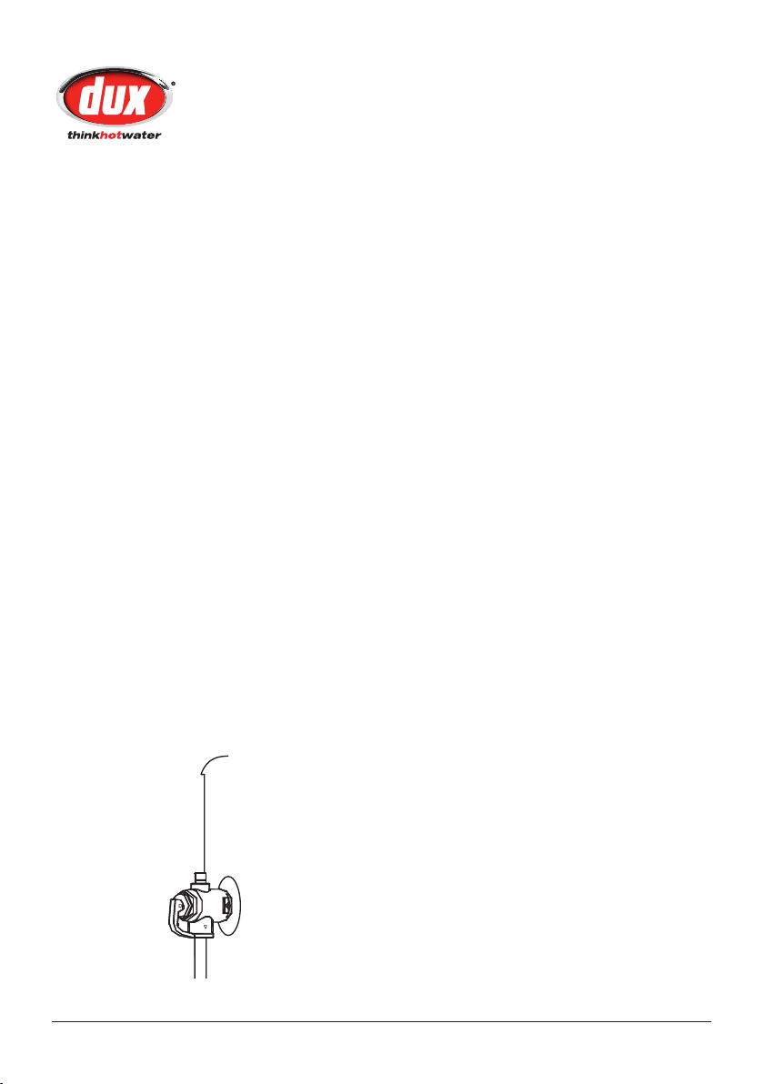
Elbow joined to
the condensate drain
Plumbing Connections
Condensation Drain
All heat pump water heaters will create
condensation from the evaporator
coil. The more humid the air, the more
condensation it will create.
The evaporator coil is located at the top
of the unit, conforming to the outside of
the tank. When condensate is created,
it runs into the “Condensate Tray” which
sits on top of the storage tank. This
then runs out through the “Condensate
Drain” which is a feature of the tray. A
copper elbow is attached to this drain
allowing easy access for the plumber to
attach the condensate drain line away
from the heater. The Airoheat louver now
incorporates a condensate drain cover,
to offer protection to the drain.
Caution: DO NOT braise the copper
elbow to a condensate drain line, this
will result in damage to the louver
section, as well as causing potential
damage to other Airoheat components.
Filling The System With Water
Once the system plumbing is completed
for the household and the Airoheat has
also been connected, the tank can be
lled with water and pressurised.
Caution: The water heater must be
lled with water before turning on the
electricity supply.
Caution: If the water heater is left in
an operating condition and unused
for two weeks or more, a quantity of
hydrogen (which is highly ammable)
may accumulate in the top of the water
cylinder. To dissipate this gas safely it is
recommended that a hot tap be turned
on for several minutes at a sink, basin
or bath, but not a dishwasher, clothes
washer or other appliance. During this
procedure there must be no smoking,
no open ame or any other electrical
appliance operating nearby. If hydrogen
is discharged through the tap it will
probably make an unusual sound similar
to that of air escaping.
 Loading...