

Page 1
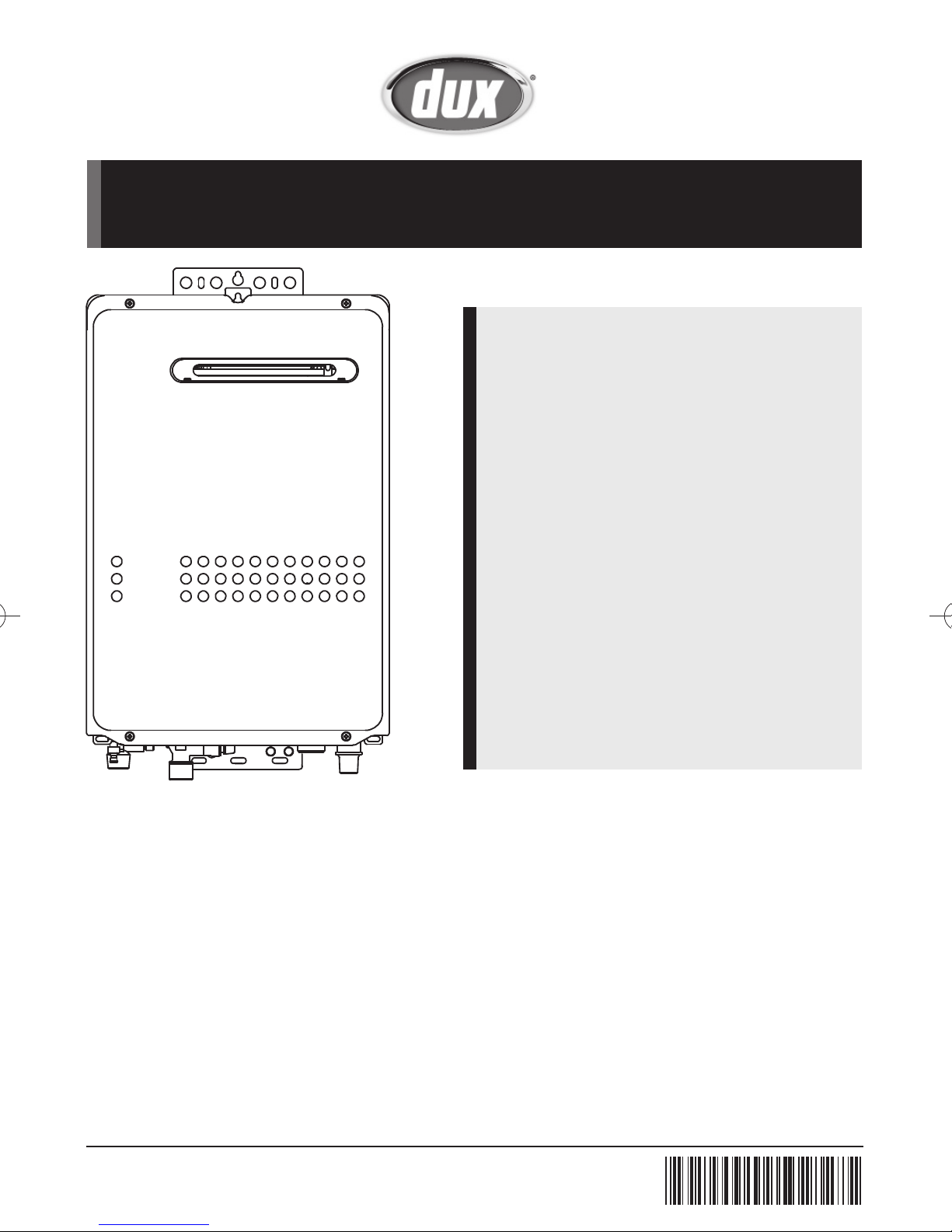
Installation Manual
Condensing Models
26ECB5N
26ECB5L
26ECB6N
26ECB6L
21ECB5N
21ECB5L
21ECB6N
21ECB6L
Non Condensing Models
21ENB5N 26ENA5N
21ENB5L 26ENA5L
21ENB6N 26ENA6N
21ENB6L 26ENA6L
17ENB5N
17ENB5L
17ENB6N
17ENB6L
Ex. 26ECB5N
To be installed and serviced only by an authorised person.
This appliance is not suitable for use as a pool heater.
The "authorised installing person" is responsible for:
1. Correct commissioning of this appliance
2. Ensure unit performs to the speci cation stated on the data label
3. Demonstrate operation of unit to customer before leaving
4. Hand these instructions to customer
This appliance must be installed in accordance with the manufacturer's installation instructions all Local Building,
Water and Gas tting regulations (AS/NZS3500.4, AS/NZS 5601, AS/NZS3000).
Failure to install this appliance in accordance with these installation instructions may void warranty.
In the interest of continued product improvement, Dux Manufacturing reserves the right to alter these speci cations
without notice.
SBB80PT
Rev. 06/16
AU Service Department : 1300 365 115
NZ Service Department : 0800 729 389
*SBB80PT*
Page 2
Contents
1. Included Accessories ............................................................................. 4
2. Optional Accessories .............................................................................. 4
3. Dimensions ............................................................................................. 5
4. Component Details Example ................................................................ 9
5. Before Installation .................................................................................. 11
6. Specifi cations ......................................................................................... 12
7. Choosing Installation Site ..................................................................... 14
Installation Manual
8. Installation Clearances .......................................................................... 15
9. Installation .............................................................................................. 17
10. Gas Piping ............................................................................................... 18
11. Water Piping ........................................................................................... 19
12. Condensate Piping ................................................................................. 21
13. Electrical Wiring ..................................................................................... 22
14. Remote controller .................................................................................. 23
15. Maintenance ........................................................................................... 26
16. Trial Operation ........................................................................................ 26
WATER QUALITY .......................................................................................... 28
2
Page 3
Installation Manual
Installation Manual
Condensing Models Non Condensing Models
26ECB5N
26ECB5L
26ECB6N
26ECB6L
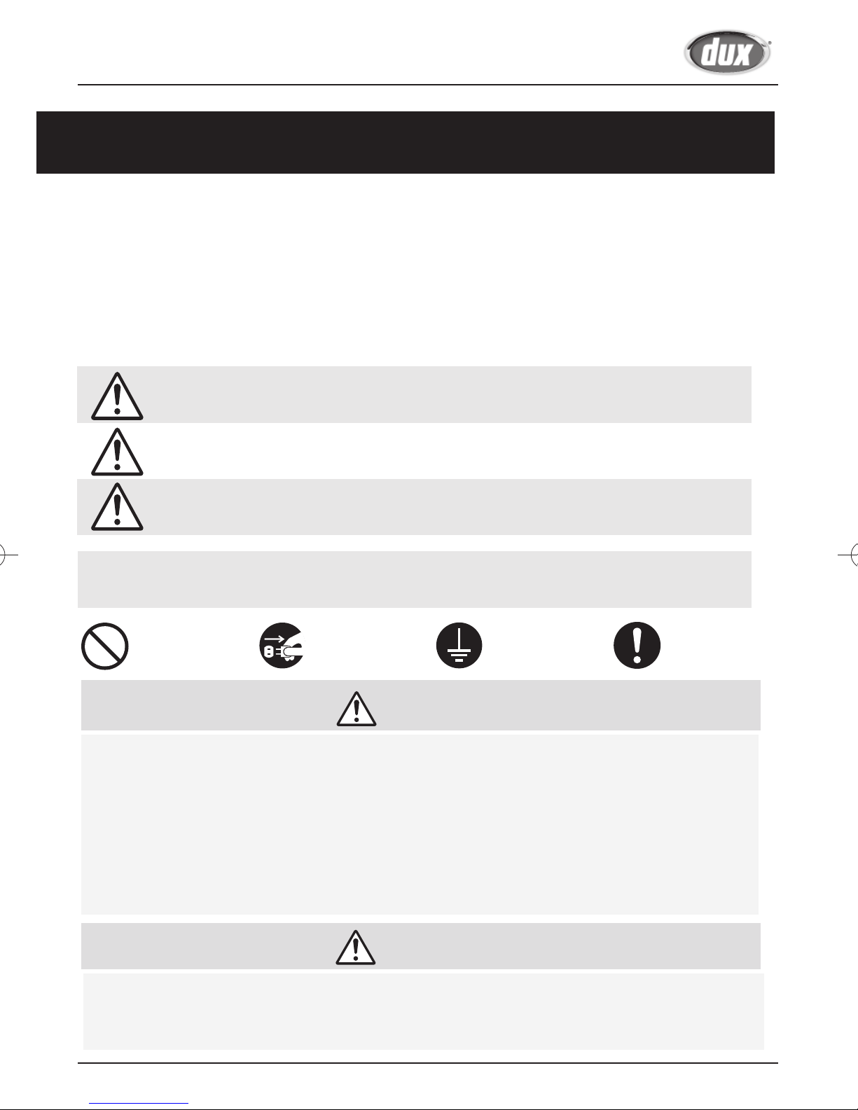
Potential dangers from accidents during installation and use are divided into the following
three categories. Closely observe these warnings, they are critical to your safety.
DANGER
WARNING
CAUTION
WARNING:
causing property damage, personal injury or death.
If the information in this manual is not followed exactly, a fi re or explosion may result
21ECB5N
21ECB5L
21ECB6N
21ECB6L
21ENB5N
21ENB5L
21ENB6N
21ENB6L
DANGER indicates an imminently hazardous situation which,
if not avoided, will result in death or serious injury.
WARNING indicates a potentially hazardous situation which, if not
avoided, could result in death or serious injury.
CAUTION indicates a potentially hazardous situation which, if not
avoided, may result in minor or moderate injury.
17ENB5N
17ENB5L
17ENB6N
17ENB6L
26ENA5N
26ENA5L
26ENA6N
26ENA6L
Prohibited
Disconnect
Power
Earth
Be sure to do
CAUTION
Requests to Installers
• In order to use the water heater safely, read this installation manual carefully, and follow the
installation instructions.
• Failures and damage caused by erroneous work or work not as instructed in this manual are not
covered by the warranty.
• Check that the installation was done properly in accordance with this Installation Manual upon
completion.
•
After completing installation, please either place this Installation Manual in a plastic pouch and
attach it to the side of the water heater,
or hand it to the customer to retain for future reference.
CAUTION
• The water heater must be commissioned including checking gas supply pressures at maximum
demand.
•
The operation of the water heater should be explained including normal operation & regular
maintenance.
3
Page 4
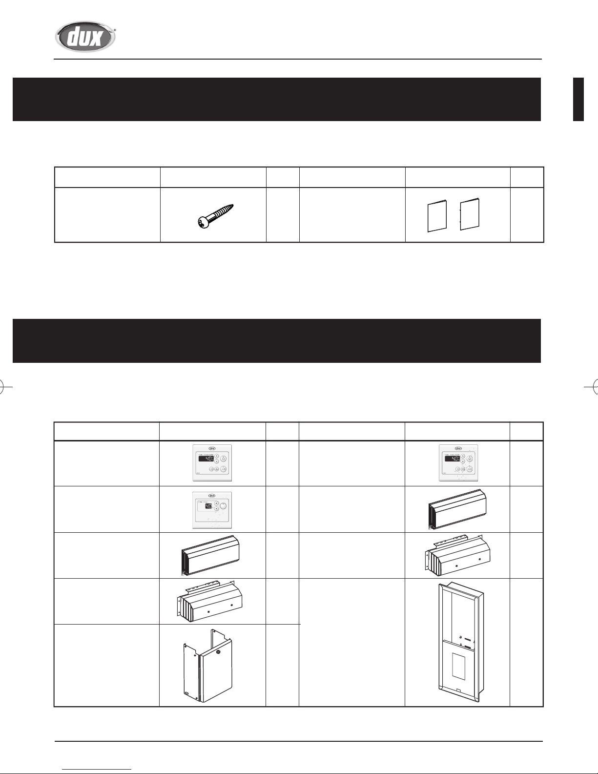
Included Accessories
The following accessories are included with the unit.
Check for any missing items before starting installation.
Installation Manual
Part Shape
Q’ty
Owner's Guide,
Anchoring Screw
5
Installation Manual
(this document)
Optional Accessories
The accessories listed below are not included with the units,
but may be necessary for installation.
Q’ty
Main Controller
(ECM1D)
MAIN
ECM1D
Bathroom Controller
1
(ECB1D)
ShapePart
Q’ty
1
each
ShapePartPart Shape
Q’ty
1
BATHROOM
ECB1D
Bathroom 2 Controller
(ECB2D)
Flue Diverter (L18)
for 26ENA series
Flue Diverter (L39)
for 17ENB series
Pipe cover
(H33-K-600)
• Maximum two Bathroom 2 controllers can be used. See P.23 for details.
4
ON/OFF
BATHROOM2
ECB2D
11
1
Flue Diverter (S37)
for 21/26ECB series
Flue Diverter (L38)
for 21ENB series
1
1
Recess Box (RBM2)
for 21/26ECB series,
17/21ENB series
1
1
Recess Box (RMM3)
for 26ENA series
Page 5
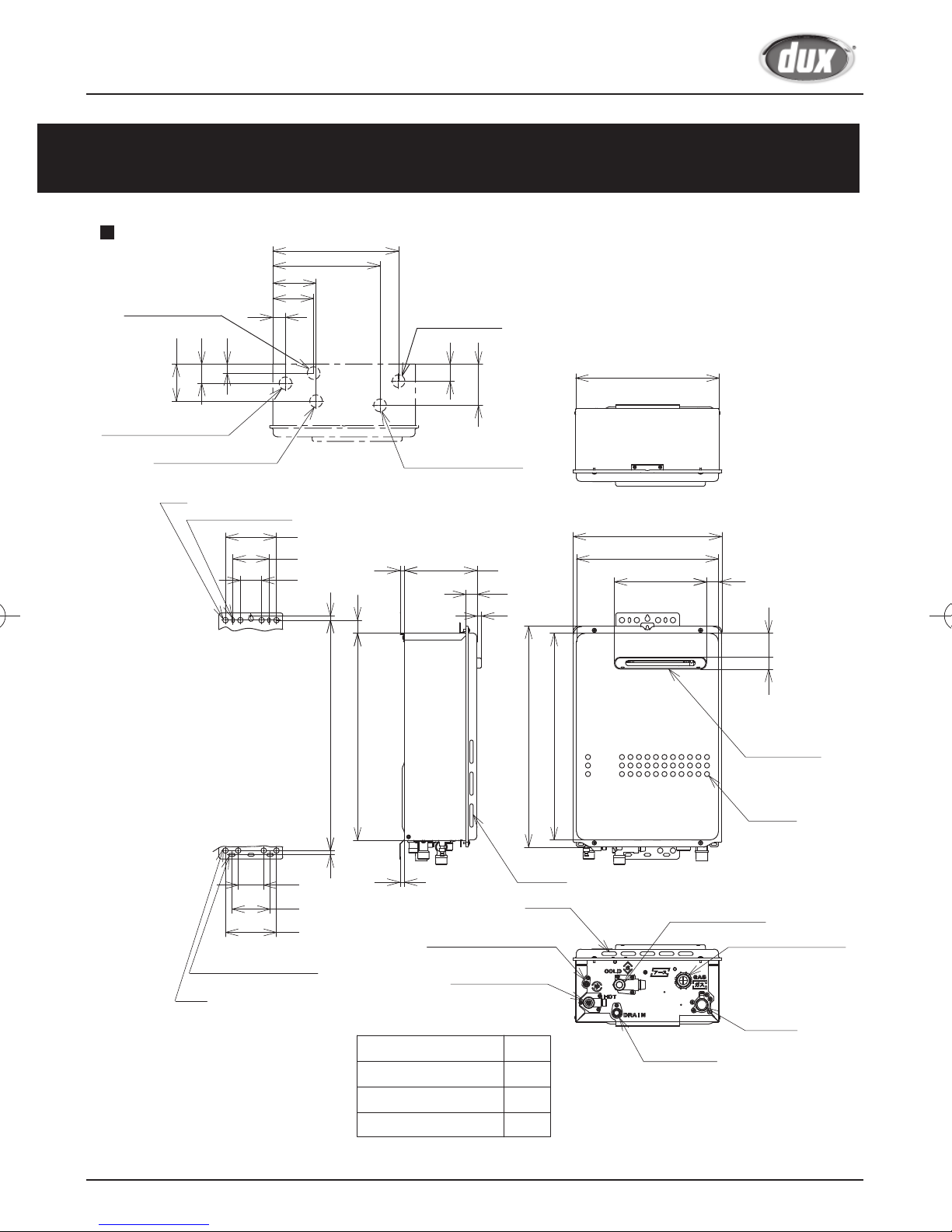
Installation Manual
Dimensions
26ECB series
DRAIN OUTLET(R1/2)
45
87
HOT WATER OUTLET(R3/4)
COLD WATER INLET(R3/4)
4-φ13
2-6×13 OBLONG HOLE
(VIEW FROM TOP)
296
252
102
96
30
21
120
85
50
10
31
GAS INLET(R3/4)
WIRING THROUGHWAYS
10
<Unit : mm>
40
97
170
27
11
338
350
334
217 28
56
2-6.5×16.5 OBLONG HOLE
4-φ13
120
28
486
54210
487
60
90
10 AIR INLET
NEUTRALIZER TANK DRAIN
HOT WATER OUTLET
HEIGHT OF EACH FITTING
FROM BOTTOM OF CASE
DRAIN OUTLET
520
AIR INLET
30
FLUE EXHAUST
AIR INLET
COLD WATER INLET
WIRING THROUGHWAYS
GAS INLET
DRAIN OUTLET
HOT WATER OUTLET 45
COLD WATER INLET 58
GAS INLET 50
5
Page 6
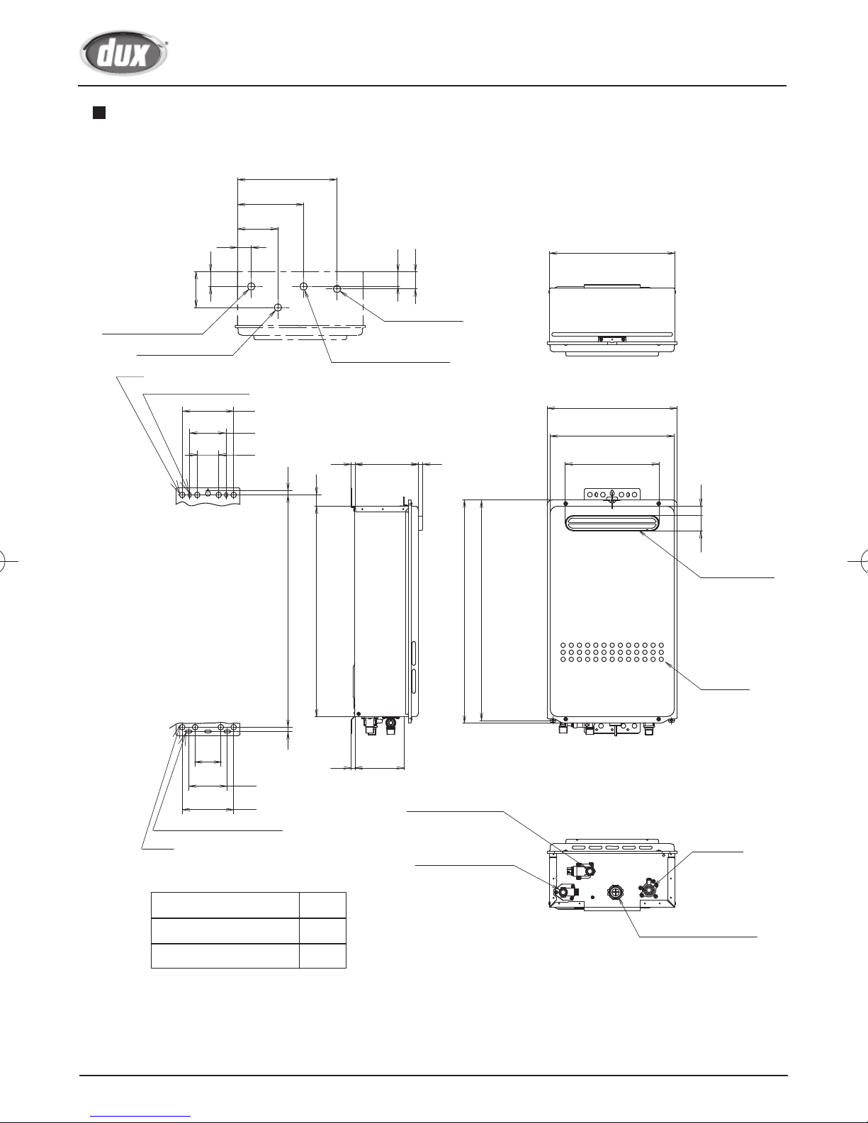
26ENA series
Installation Manual
(VIEW FROM TOP)
268
178
109
37
40
97
47
40
338
<Unit : mm>
HOT WATER OUTLET(R3/4)
COLD WATER INLET(R3/4)
4-φ13
2-6×13 OBLONG HOLE
120
85
50
GAS INLET(R3/4)
WIRING THROUGHWAYS
350
334
10 11
10
31
567
62210
170
600
566
253
42 25
FLUE EXHAUST
AIR INLET
60
84
120
3-6.5×16.5 OBLONG HOLE
4-φ13
HEIGHT OF EACH FITTING
FROM BOTTOM OF CASE
HOT WATER OUTLET 44
COLD WATER INLET 48
GAS INLET 49
6
10 133
COLD WATER INLET
GAS INLET
HOT WATER OUTLET
WIRING THROUGHWAYS
Page 7
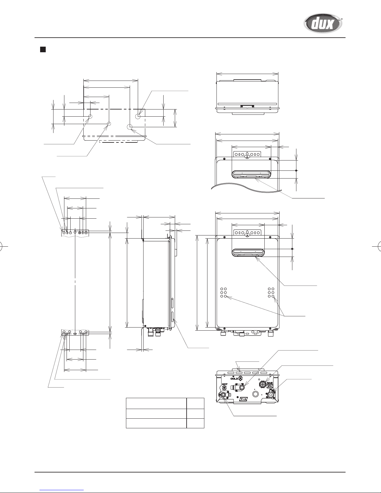
Installation Manual
17/21ENB series
37
40
80
HOT WATER
OUTLET(R3/4)
COLD WATER
INLET(R3/4)
4-φ13
2-6ᨴ13 OBLONG HOLE
᧤VIEW FROM TOP᧥
296
252
139
120
85
50
10542
<Unit : mm>
GAS INLET(R3/4)
40
97
338
21ENB Series
350
WIRING
THROUGHWAYS
334
214 37
42 57
FLUE EXHAUST
17ENB Series
10
31
170
27
11
350
334
178
73
60
90
120
3-6.5ᨴ16.5 OBLONG HOLE
4-φ13
487
10
10
HEIGHT OF EACH FITTING
FROM BOTTOM OF CASE
HOT WATER OUTLET
COLD WATER INLET
GAS INLET
520
AIR INLET
45
48
50
486
AIR INLET
HOT WATER OUTLET
42 57
FLUE EXHAUST
AIR INLET
COLD WATER INLET
WIRING THROUGHWAYS
GAS INLET
7
Page 8
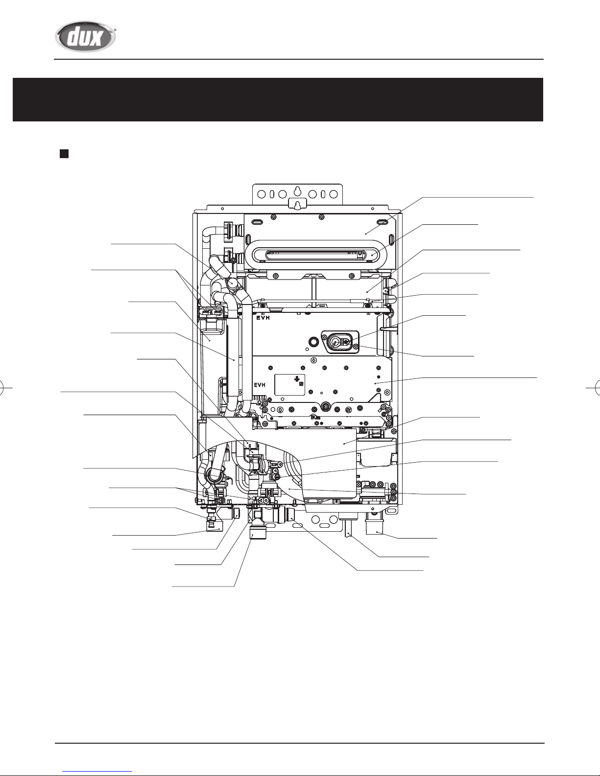
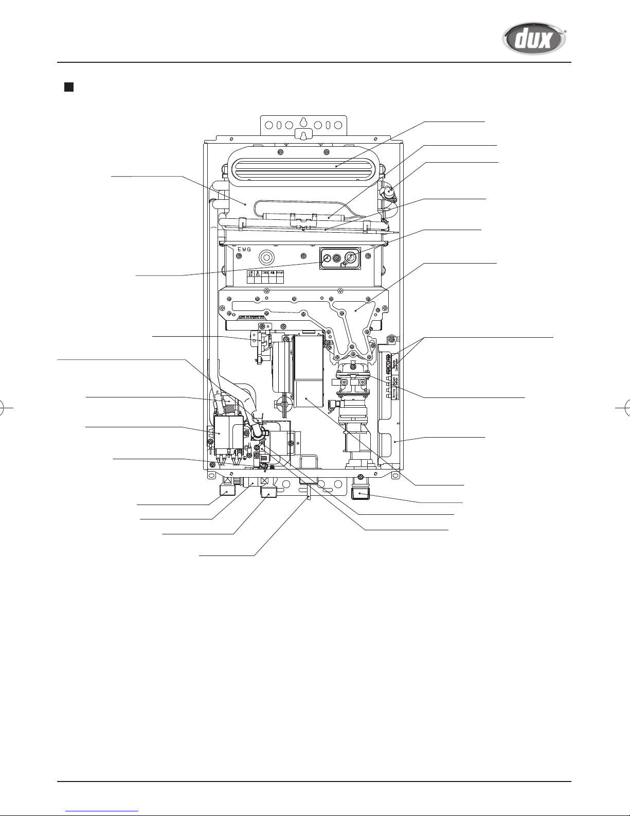
Component Details Example
26ECB series model shown for illustration only
Installation Manual
Secondary heat exchanger
Flue exhaust
High limit switch
Water level electrode
Neutralizer
Anti-frost heater
Igniter
Freeze protection thermostat
Main flow control valve
Water outlet thermistor
Anti-frost heater
Neutralizer tank drain
Primary heat exchanger
Anti-frost heater
Thermal fuse
Flame rod
Ignition plug
Burner manifold & gas valve
Circuit board
Water inlet thermistor
Water flow sensor
Fan motor
Hot water outlet
Pressuer relief valve
Drain outlet
Cold water inlet
8
Gas inlet
Power code
Inlet water filter
Ex. 26ECB5N
Page 9
Installation Manual
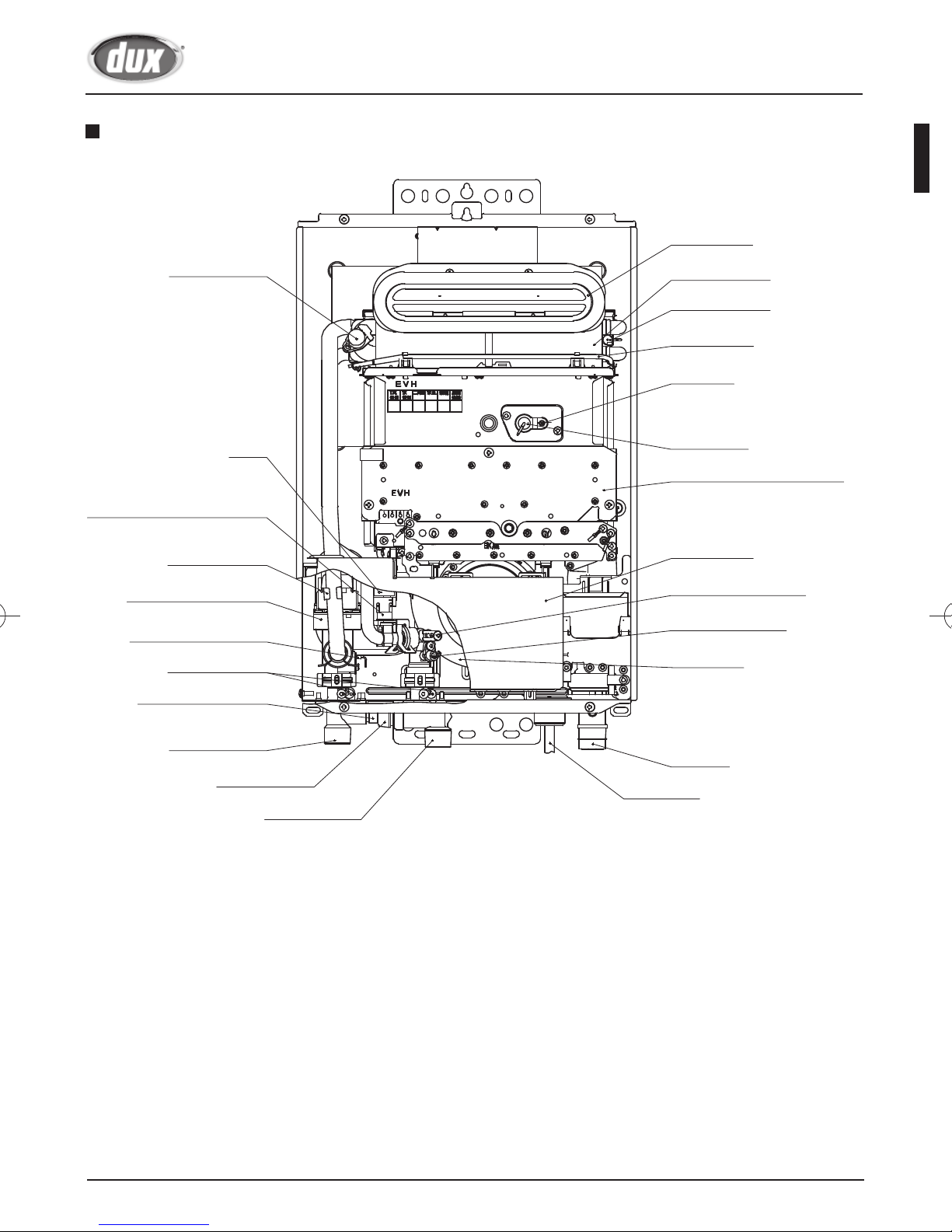
26ENA series model shown for illustration only
Heat exchanger
Flame rod
Flue exhaust
Anti-frost heater
High limit switch
Thermal fuse
Ignition plug
Burner manifold
Igniter
Freeze protection thermostat
Main flow control valve
Earth leakage breaker
Anti-front heater
Hot water outlet
Inlet water filter
Cold water inlet
Remote Control Connections
Gas solenoid valve set
Circuit board
Fan motor
Gas inlet
Water inlet thermistor
Water flow sensor
Power code
Ex. 26ENA5N
9
Page 10
21ENB series model shown for illustration only
Installation Manual
Flue exhaust
High limit switch
Igniter
Freeze protection thermostat
Anti-frost heater
Main flow control valve
Water outlet thermistor
Anti-frost heater
Pressure relief valve
Heat exchanger
Anti-frost heater
Thermal fuse
Flame rod
Ignition plug
Burner manifold & gas valve
Circuit board
Water inlet thermistor
Water flow sensor
Fan motor
Hot water outlet
Inlet water filter
Gas inlet
Power code
Cold water inlet
Ex. 21ENB5N
10
Page 11
Installation Manual
Before Installation
WARNING
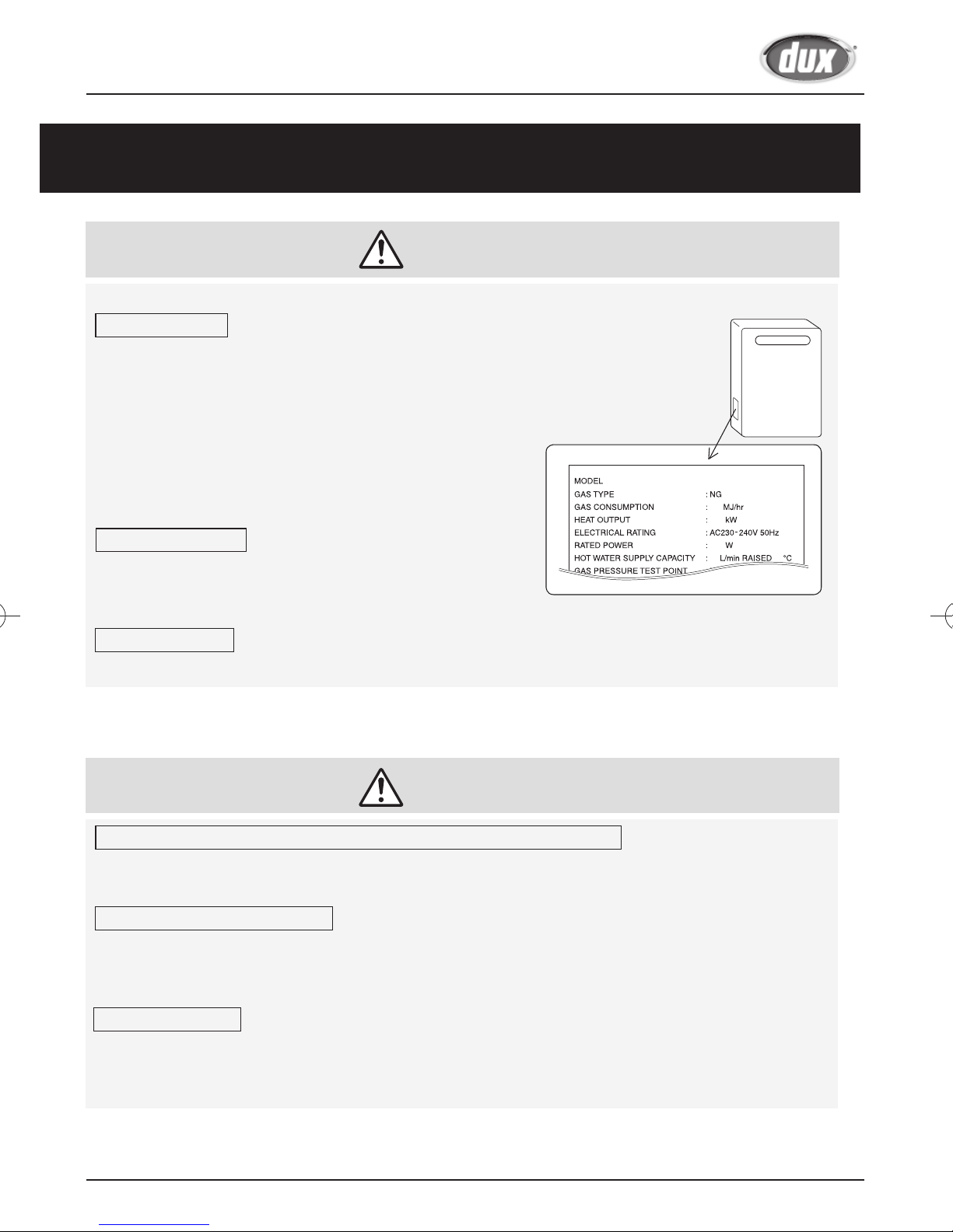
Check the Gas
• Check that the data label (left side of casing).
• Check that the gas supply line is sized for
26ECB5(6)N, 26ECB5(6)L: 175 MJ/hr, 185 MJ/hr
21ECB5(6)N, 21ECB5(6)L: 145 MJ/hr, 149MJ/hr
26ENA5(6)N, 26ENA5(6)L: 199 MJ/hr, 199 MJ/hr
21ENB5(6)N, 21ENB5(6)L: 159 MJ/hr, 158 MJ/hr
17ENB5(6)N, 17ENB5(6)L: 125.5 MJ/hr, 130 MJ/hr
• DO NOT OPERATE WITH ANY OTHER GAS TYPE.
Check the Power
• The power supply required is 230 - 240VAC, at 50Hz.
Using the incorrect voltage may result in fi re or
electric shock.
For NG Gas
xxxxxxxx
xx
xx
xx
xx xx
Warning labels
• Located on the front and left hand side of the casing -PLEASE READ THESE LABELS CAREFULLY!
CAUTION
Do Not Use Equipment for Purposes Other Than Those Specifi ed
• Do not use for other than increasing the temperature of the water supply, as unexpected accidents
may occur as a result.
Check Water Supply Quality
• If the water supply is hard, acidic or otherwise impure, treat the water with approved methods in
order to ensure full warranty coverage.
See water quality statement on page 28.
Frost Protection
• When installed, power to the unit must be kept switched on, otherwise the appliance should be
drained.
This prevents water freezing, and causing damage to the water heater.
11
Page 12
Installation Manual
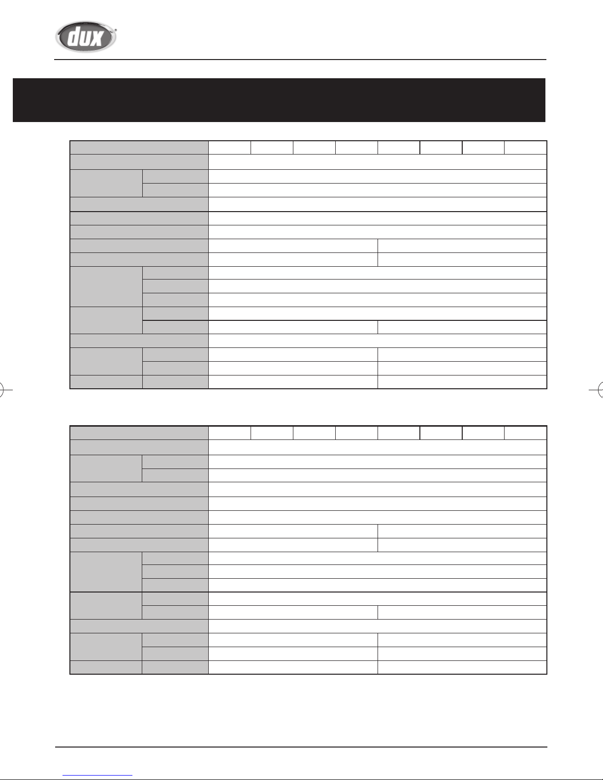
Speci cations
Model Name 26ECB5N 26ECB5L 26ECB6N 26ECB6L 21ECB5N 21ECB5L 21ECB6N 21ECB6L
Approval certification number SAI-400194
Type
Operating Pressure 200 -1,000 kPa
Minimum Flow Rate 2.5 L/min.
Dimensions 520mm (Height) x 350mm (Width) x 170mm (Depth)
Weight 18 kg 17 kg
Water Holding Capacity 0.9 L 0.8 L
Connection Sizes
Power Supply
Accessories Anchoring Screws
Gas
Consumption
Maximum Hot Water
Installation Outdoor, Wall Mounted
Air Supply/Exhaust
Water Inlet R 3/4 (20mm)
Hot Water Outlet R 3/4 (20mm)
Gas Inlet R 3/4 (20mm)
Supply 230 - 240 VAC (50Hz)
Consumption
NG 175 MJ/hr 145 MJ/hr
LP 185 MJ/hr 149 MJ/hr
25°C Rise 26 L/min 21 L/min
NG/LP: 49.0W/60.0W Freeze Prevention 130W NG/LP: 43.0W/52.0W Freeze Prevention 130W
Power Flue
Model Name 21ENB5N 21ENB5L 21ENB6N 21ENB6L 17ENB5N 17ENB5L 17ENB6N 17ENB6L
Approval certification number SAI-400195
Type
Operating Pressure 200 -1,000 kPa
Minimum Flow Rate 2.5 L/min.
Dimensions 520mm (Height) x 350mm (Width) x 170mm (Depth)
Weight 15 kg 14 kg
Water Holding Capacity 0.5 L 0.5L
Connection Sizes
Power Supply
Accessories Anchoring Screws
Gas
Consumption
Maximum Hot Water
Installation Outdoor, Wall Mounted
Air Supply/Exhaust
Water Inlet R 3/4 (20mm)
Hot Water Outlet R 3/4 (20mm)
Gas Inlet R 3/4 (20mm)
Supply 230 - 240 VAC (50Hz)
Consumption
NG 159 MJ/hr 125.5 MJ/hr
LP 158 MJ/hr 130 MJ/hr
25°C Rise 21 L/min 17 L/min
NG/LP: 36.0W/49.0W Freeze Prevention 129W NG/LP: 31.0W/41.0W Freeze Prevention 129W
Power Flue
12
Page 13
Installation Manual
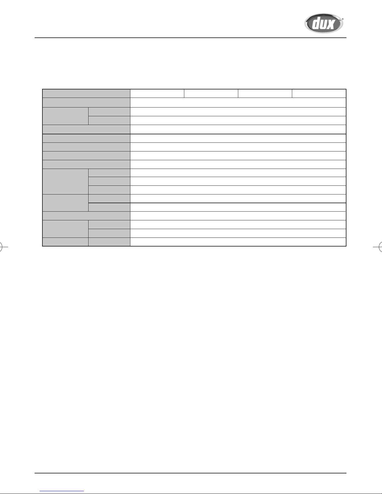
Model Name 26ENA5N 26ENA5L 26ENA6N 26ENA6L
Approval certification number SAI-400195
Type
Operating Pressure 200 -1,000 kPa
Minimum Flow Rate 2.5 L/min.
Dimensions 600mm (Height) x 350mm (Width) x 170mm (Depth)
Weight 19 kg
Water Holding Capacity 0.9 L
Connection Sizes
Power Supply
Accessories Anchoring Screws
Gas
Consumption
Maximum Hot Water
Installation Outdoor, Wall Mounted
Air Supply/Exhaust
Water Inlet R 3/4 (20mm)
Hot Water Outlet R 3/4 (20mm)
Gas Inlet R 3/4 (20mm)
Supply 230 - 240 VAC (50Hz)
Consumption NG/LP: 51.3W/51.3W Freeze Prevention 129W
NG
LP
25°C Rise 26 L/min
Power Flue
199 MJ/hr
199 MJ/hr
• Specifi cations may be changed without prior notice.
• The capacity may differ slightly, depending on the water pressure,
water supply, piping conditions, and water temperature.
13
Page 14
Installation Manual
Choosing an Installation Site
* Locate the appliance in an area where water leakage from the unit or connections will not result in
damage to the area adjacent to the appliance or to the lower fl oors of the structure. When such locations
cannot be avoided, it is recommended that a suitable drain pan, adequately drained, be installed under
the appliance. The pan must not restrict combustion air fl ow.
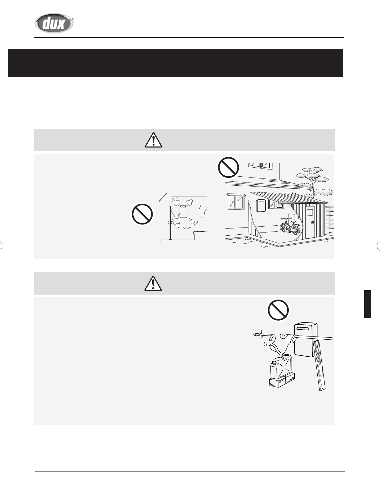
DANGER
• This water heater is for outdoor installation only.
Never install it indoors.
Do not enclose the termination with corrugated
metal or other materials.
This will cause carbon monoxide
poisoning and a potential fi re
hazard.
Indoor
WARNING
• Avoid places where fi res are common, such as those where petrol,
benzene and adhesives are handled, or places in which corrosive gases
(ammonia, chlorine, sulfur, ethylene compounds, acids) are present.
May result in fi re.
• Avoid installation in places where dust or debris will accumulate.
Dust may block the air-supply opening, causing the performance of the
device fan to drop and incomplete combustion to occur as a result.
• Avoid installation in places where special chemical agents
(e.g., hair spray or spray detergent) are used.
Ignition failures and malfunction may occur as a result.
Prohibited
• Carbon Monoxide Poisoning Hazard. Do not install this water heater in a
mobile home, recreation vehicle or on a boat.
14
Page 15
Installation Manual
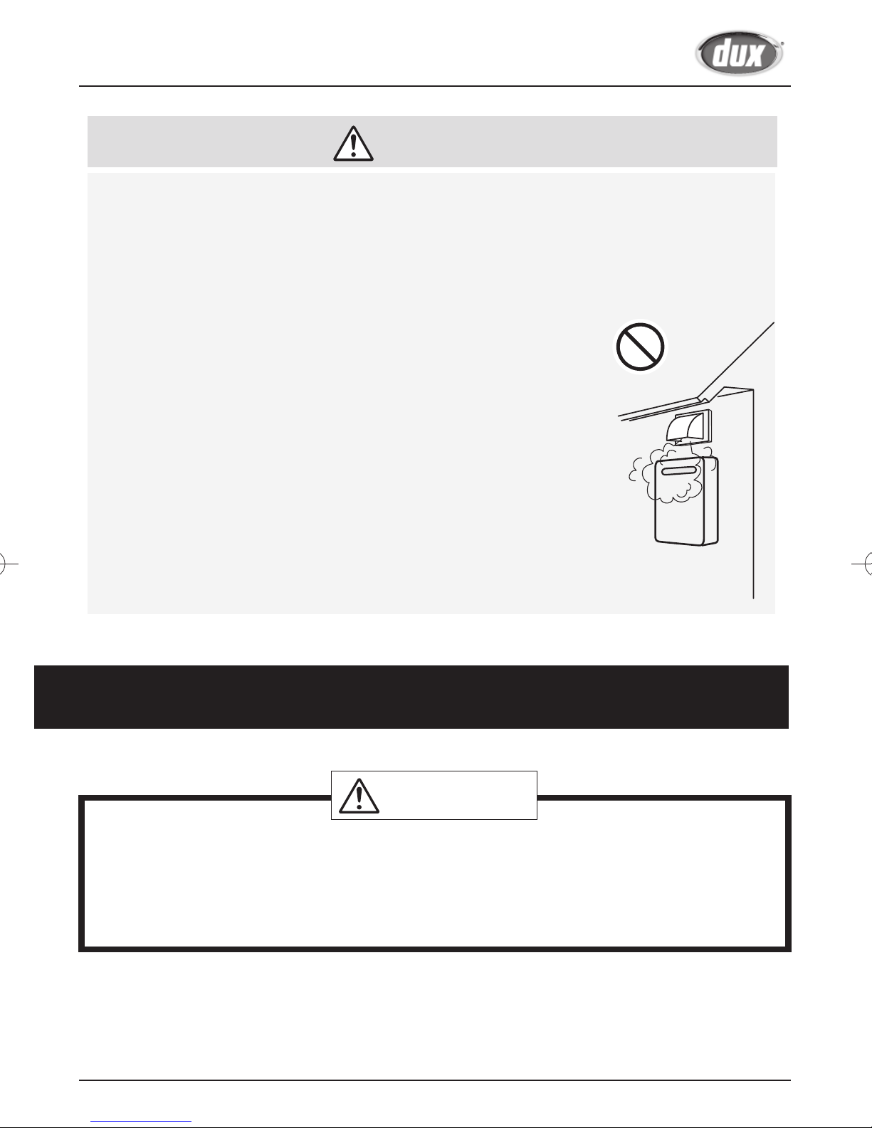
CAUTION
• Install the water heater in a location where it is free from obstacles and
stagnant air.
• Consult with the customer concerning the location of installation.
• Do not install the water heater near staircases or emergency exits.
• Do not install the water heater where the exhaust will blow on outer walls
or material not resistant to heat. Also consider the surrounding trees and
animals.
The heat and moisture from the water heater may cause discoloration of
walls and resinous materials, or corrosion of aluminium materials.
• Do not locate the vent termination directed towards a window or any other
structure which has glass or wired glass facing the termination.
• Install in a location where the exhaust gas fl ow will not be affected by fans
or range hoods.
• Take care that noise and exhaust gas will not affect neighbours.
• Avoid installation where the unit will be exposed to excessive winds.
• Before installing, make sure that the vent termination will have the proper
clearances according to AS/NZS5601, or your local authority.
• On combustible surfaces e.g. weatherboards etc. it is not required to install
a fi re proof back board.
Installation Clearances
Prohibited
Before installing, check for the following:
The location of the fl ue terminal must comply with the clearances shown on this page. If you are
unsure about clearances not indicated here, in general refer to AS/NZS5601, or your local authority. In
Western Australia refer to the WA Offi ce of Energy rules and regulations.
Flue outlet must be free from any combustible material.
WARNING
15
Page 16
16
Installation Manual
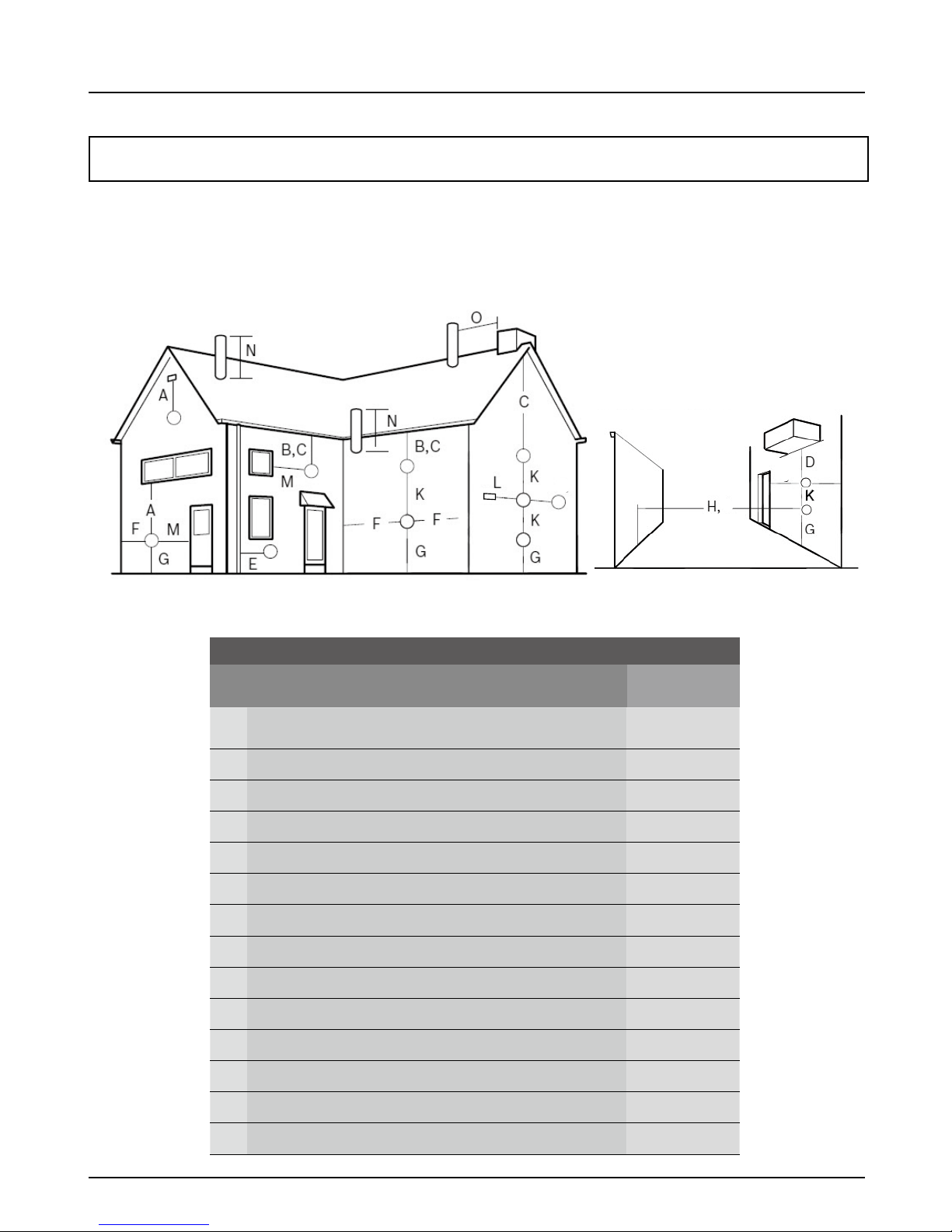
CLEARANCES FOR FLUE TERMINAL (front of heater)
The location of the flue terminal must comply with the clearances shown on this page. If you are unsure
about clearances not indicated here, in general refer to AS/NZS5601, or your local authority. In Western
Australia refer to the WA Office of Energy rules and regulations.
Key to illustration
Balanced flue terminal position
Terminal position
Minimum
Spacing
A
Directly below an opening window, air vent or
other ventilation opening*
1,500mm
B Below guttering 300mm
C Below eaves 300mm
D
Below balconies or a car port roof 300mm
E From vertical drain pipes or soil pipes 75mm
F From internal or external corners 300mm
G Above adjacent ground, roof or balcony level 300mm
H From a surface facing the terminal 500mm
J From a terminal facing the terminal 500mm
K From any other flue terminal or combustion air intake 300mm
L From a mechanical air inlet including spa blower 1000mm
M Adjacent to opening 300mm
N Above intersection with roof 500mm
O For a vertical structure on the roof 500mm
J
M
K
*21ECB and 17ENB models to have
1000mm minimum spacing.
Page 17
Installation Manual
Installation
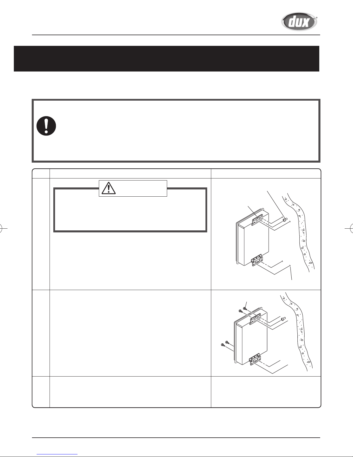
Securing to the wall
• Installation must conform with all local building, water or Gas Regulations or AS/NZS5601.
• The weight of the device will be applied to the wall. If the strength of the wall is not suffi cient,
reinforcement must be done to prevent the transfer of vibration.
• Do not drop or apply unnecessary force to the device when installing. Internal parts may be
Be sure to do
damaged and may become highly dangerous.
• Install the unit on a vertical wall and ensure that it is level.
• Insure no additional pressure is applied to the pipework.
Item
Locating Screw Holes
Mounting
CAUTION
• When installing with bare hands, take caution to not
infl ict injury.
• Be careful not to hit electrical wiring, gas, or water
piping while drilling holes.
1. Drill a single screw hole, making sure to hit a stud.
2. Insert and tighten the screw and hang the unit by
the upper wall mounting bracket.
3. Determine the positions for the remaining four screws
(two for the top bracket and two for the bottom), and
remove the unit.
4. Drill holes for the remaining four screws.
5. Hang the unit again by the fi rst screw, and then
insert and tighten the remaining four screws.
6. Take waterproofi ng measures so that water does
not enter the building from screws mounting the
device.
IllustrationCheck
Location of Screw Hole
Mounting Bracket
(upper)
Locating Screw Holes
Anchoring Screw
• Make sure the unit is installed securely so that it will
not fall or move due to vibrations or earthquakes.
Structure
17
Page 18
Installation Manual
Gas Piping
Follow the instructions from the gas supplier.
The appliance must be disconnected from the gas supply piping system during any pressure testing of
that system at test pressures in excess of 3.5 kPa.
The appliance and its gas connections must be leak tested before placing the appliance in operation.
The inlet gas pressure must be within the range specifi ed. This is for the purposes of input adjustment.
In order to choose the proper size for the gas line, consult local codes and / or the AS/NZS5601.
Gas Pressure
Size the gas line according to total MJ/h
demand of the building and length from
the meter or regulator so that the following
supply pressures are available even at
maximum demand refer AS/NZS5601:
Working Gas Supply Pressures
Natural Gas Supply Pressure
Min. 1.13 kPa
Max. 3.00 kPa
LP Gas Supply Pressure
Min. 2.75 kPa
Max. 3.50 kPa
• Please ensure measurement is taken
when the appliance is operating at
maximum load.
Gas Meter
Select a gas meter capable of supplying
the entire MJ/h demand of all gas appliances
in the building.
Gas Connection
1) Fit a union to the water heater gas inlet for easy
connection and removal. The thread diameter is 20
mm.
THIS DOES NOT INDICATE THE SIZE OF THE GAS
SUPPLY.
2) Fit an suitably approved isolating gas cock in the supply
line adjacent to the water heater gas connection.
3) Ensure that the supply pipe and the gas pressure
regulator (LPG or Natural Gas) has suffi cient fl ow
capacity for this and other appliances connected to the
fi tting line.
4) For LPG appliances ensure that gas cylinders are of
suffi cient size. The water heater alone will require 2 x 45
Kg capacity cylinders.
5) Before connecting the appliance to the gas service,
purge any debris or air from the gas service.
6) Check all joints for leaks with an approved leak tester
after connection.
Measuring Gas Pressure
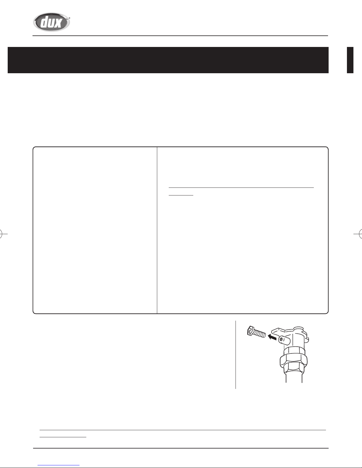
In order to check the gas supply pressure to the unit, a tap is provided
on the gas inlet. Remove the hex head philips screw from the tap,
and connect a manometer using a silicon tube.
In order to check the gas manifold pressure on the gas valve inside
the unit. The pressure can be checked by removing the hex head
philips screw and connecting a manometer with a silicon tube.
Refer to AS/NZS5601 for pipe sizing and details.
Ensure that the gas pipe size is correct. If undersized the appliance will not operate correctly
SERVICE CALLS ARE CHARGEABLE FOR UNITS WITH INCORRECT PIPE SIZES OR BLOCKED GAS OR
WATER FILTERS.
18
Page 19
Installation Manual
Water Piping
Installation and service must be performed by a qualifi ed plumber. Observe all applicable codes.
This appliance is suitable for potable water applications. Do not use this appliance if any part has been underwater.
Immediately call a qualifi ed service technician to inspect the appliance and replace any part of the control system
and gas control which has been under water.
Piping and components connected to the water heater shall be suitable for use with potable water.
Toxic chemicals, such as those used for boiler treatment, shall not be introduced into the potable water.
A water heater used to supply potable water may not be connected to any heating system or components
previously used with a nonpotable water heating appliance.
When water is required in one part of the system at a higher temperature than in the rest of the system, means
such as a mixing valve shall be installed to temper the water to reduce the scald hazard.
• Flush water through the pipe to clean out metal powder, sand and dirt before connecting it.
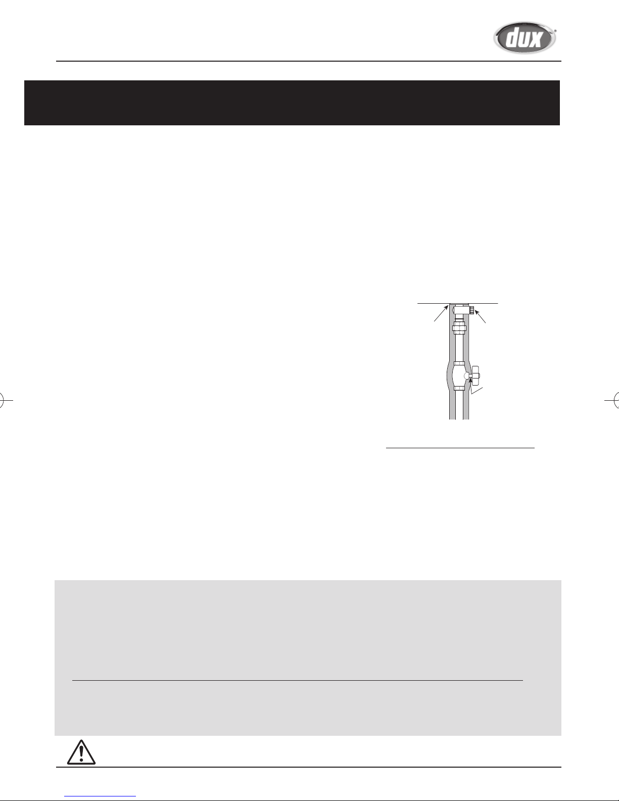
• Perform the following insulation measures for prevention of freezing.
• Take appropriate heat insulation measures (e.g., wrapping with heat
insulation materials, using electric heaters) according to the climate
of the region to prevent the pipe from freezing.
• Make sure that there are no water leaks from the cold and hot water
supply pipes, then insulate the pipes completely.
• Be sure to also completely insulate the water supply valve and the
cold and hot water connections on the water heater (refer to the
fi gure on the right).
• Do not cover the water drain plug with insulation so that water in the
pipe can be drained. (Refer to the fi gure in the right.)
•
Use a union coupling for connecting the pipes to reduce the force applied to the piping.
• When feed water pressure is too high, insert a depressurizing valve, or take water hammer prevention measure.
• Avoid using joints as much as possible to keep the piping simple.
• Avoid piping in which an air lock can occur.
•
Use approved piping materials.
• If installing the unit on a roof (Above lower-level hot water supply):
If the unit is installed on a roof to supply water to the levels below, make sure that the water pressure supplied
to the unit does not drop below 199 kPa. It may be necessary to install a pump system to ensure that the water
pressure is maintained at this level.
Check the pressure before putting the unit into operation.
Failure to supply the proper pressure to the unit may result in noisy operation, shorter lifetime of the unit, and may
cause the unit to shut down frequently.
Completely insulate
the water inlet and
outlet fittings.
Do not cover the water
drain plug with insulation
so that water in the pipe
can be drained.
Insulate the water
supply valve completely.
Supply water piping
• Do not use PVC, iron, or any piping which has been treated with chromates, boiler seal or other chemicals.
• Pipe sizing from the cold water supply should be sized according to local BY LAWS for water supply.
• If sludge or foreign matter is present in the water supply it is recommended that a separate fi lter/strainer be
fi tted to the cold water supply line.
• A GATE VALVE OR BALL VALVE must be used on the cold water inlet to the water heater. THIS
REQUIREMENT IS AN AUSTRALIA WIDE REQUIREMENT UNDER THE NATIONAL PLUMBING CODE.
STOP TAPS OR COMBINATION STOP TAPS AND NON-RETURN VALVES ARE NOT TO BE USED.
• In order for the client to use the water heater comfortably, 200 to 1000 kPa of pressure is needed from the
water supply.
Be sure to check the water pressure. If the water pressure is low, the water heater cannot perform to its full
capability, and may become a source of trouble for the client.
Please ensure this appliance does not receive inlet water greater than 85°C when used as a Solar booster.
19
Page 20
Installation Manual
Drain processing
• Expansion water may drop from the pressure relief valve and wet the fl oor.
Hot water piping
• Do not use lead, PVC, iron or any piping which has been treated with chromates, boiler seal or other
chemicals.
• Keep the pipe lengths to a minimum, and make sure that the pipework is well insulated as correct
performance of the appliance is dependent on properly insulated pipework.
• DO NOT FIT ANY VALVES OR RESTRICTORS TO THE OUTLET OF THE WATER HEATER.
• DO NOT FIT ANY OBSTRUCTION TO THE PRESSURE RELIEF LOCATED ON THE HOT WATER OUTLET
CONNECTION.
• Use mixing valves with low water resistance. Use shower heads with low pressure loss.
• If necessary, use a pump or other means to ensure that the supply water pressure to the inlet of the heater
does not fall below 199kPa when the maximum amount of water is being demanded. If the water pressure
drops below 200 kPa, local boiling can occur inside the water heater causing abnormal sounds and
decreasing the durability of the heat exchanger.
After purging the air from the system using the hot water supply taps, remove the water inlet strainer located
on the cold water supply inlet connection. Remove any debris from the fi lter and replace. When replacing the
fi lter, do not over-tighten the “O” ring seal.
For units which are not 50˚C compliant, it is recommended that for sanitary fixtures use primarily for the
purpose of personal hygiene, that a temperature control device be fitted (such as a tempering valve) as per
AS3498.
No pressure reduction is required unless the water pressure exceeds 1000kPa.
50˚C Compliant Models Only
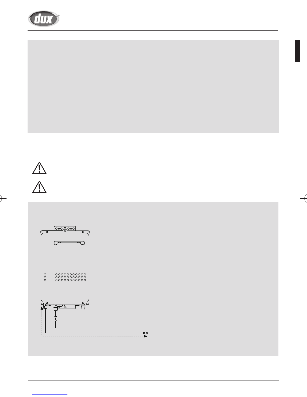
In order to comply with AS3498 the minimum distances as per the diagram below must be observed.
Commission Check for 50˚C Temperature Delivery
A temperature check must be completed at the nearest
outlet to the water heater to ensure delivered water is
below 50˚C.
To check the water temperature is below 50˚C.
1. At the closest outlet adjust the hot water flow to at
least 5 litres/min.
2. After hot water has been running for 1 min confirm
the water temperature is below 50˚C.
3. Turn the water off
Cold
Closest hot
15mm (min) 2m (min)
water outlet
20
Page 21
Installation Manual
Condensate Piping
ONLY APPLICABLE TO CONDENSING MODELS.
PLEASE FOLLOW LOCAL CODES ABOUT PIPING.
• This water heater is a high effi ciency, fully condensing appliance which produces condensate during
operation. Therefore, it is necessary to install condensate piping. The water heater incorporates a
collection, neutralization, and removal system which must be properly drained in order to ensure proper
operation of this appliance.
• The water heater is supplied with a pre-installed condensate neutralization system. No additional
neutralizer is required unless local code dictates otherwise.
• In order to drain the condensate, a 15mm (1/2" BSP) male thread fi tting is provided at the base of the
water heater.
DO NOT FIT ANY VALVES OR REDUCE THE SIZE OF THIS FITTING OR THE CONDENSATE PIPING TO
LESS THAN 15mm (1/2" BSP).
• Use plastic pipe, such as PVC, for the drain line. Do not use steel, black iron, or any other material which
can corrode when placed into contact with water.
• Keep the length of the drain pipe as short as possible.
• Horizontal runs must be sloped 1/50 downwards the drain.
• The end of the drain pipe must not be submerged in water or blocked in any way.
• Be sure to check that condensate is freely flowing from the drain piping after the system has been
installed. Condensate will begin fl owing out of the water heater within 15 minutes after operation has
started.
• Take measures to prevent the condensate drain lines from freezing (insulation, heat tape, electric heaters,
etc.).
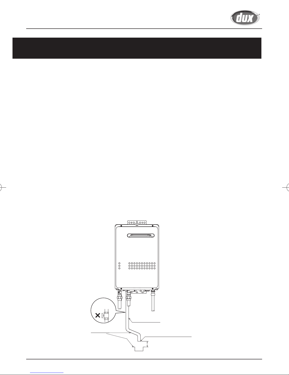
Condensate piping to floor drain
Condensing models only
DO NOT FIT
ANY VALVES
Slope pipe
downwards 1/50.
Floor drain
1/2" PVC pipe
The end of the drain pipe
must have an air gap.
KEEP CLEARANCE
21
Page 22
Installation Manual
Electrical Wiring
WARNING
Electrical Shock Hazard
Do not turn power on until controllers have been connected. Disconnect power before servicing.
Failure to do so may result in death or serious injury from electrical shock.
• The appliance is equipped with a 1.5m cable with a three pinned earthed plug to be connected to
230
240VAC at 50 Hz.
-
The power consumption may be up to 21/26ECB series 177W, 17/21ENB series 181W, 26ENA series 000W.
Use an appropriate circuit.
• The appliance requires a 240V in Australia and 230V in New Zealand, 50Hz weatherproof plug installed in a protected position adjacent to the appliance.
• If the power cord is damaged and requires replacement, use only an original spare part available from
the manufacturer.
• Do not disconnect the power supply when not in use. When the power is off, the freeze prevention in
the water heater will not activate, resulting in possible freezing damage.
• Do not let the power cord contact the gas piping.
Tie the excess power cord outside the water heater. Putting the redundant length of cord inside
the water heater may cause electrical interference and faulty operation.
Earth
• To prevent electrical shock, always plug power lead into an earthed point.
CAUTION
Electrostatic discharge can affect electronic components. Take precautions to prevent electrostatic discharges from personnel or hand tools during the water heater installation and servicing to protect product’s electronic control.
22
Page 23
Installation Manual
Remote Controller
Applicable Model
Remote controller
Main controller
Bathroom controller
Bathroom 2 controller
ECM1D
ECB1D
ECB2D
* Maximum temperature is controlled by the maximum default temperature set in the water heater.
The following combination of remote controls will operate the water heater.
Only Main Controller Works
Only Bathroom Controller Won't work
Only Bathroom 2 Controller Won't work
Main & Bathroom Controller Works
Main, Bathroom & 1 or 2 Bathroom 2 Controllers Works
Main & Bathroom 2 Controller Won't work
Bathroom & Bathroom 2 Controller Won't work
Max temperature 60°C * (75°C : 26ENA6N/L only)
Max temperature 50°C *
Max temperature 50°C *
The bathroom controllers have a maximum temperature setting of 50°C for safety. To ensure compliance with Australian
Standard AS/NZS3500.4, for sanitary areas, install either a 50°C model or a 55/60/75°C (75°C is 26ENA6N/L only)
model with a tempering valve. In New Zealand, please refer to the New Zealand Building Code and all other applicable
electrical, gas fi tting and plumbing codes.
°
The maximum temperature allowed can be changed on both the 50
only)
models with the insertion of a bridge. With the bridge inserted on the 50°C model this will change the
temperature to a maximum of 42°C. The
°
C and with the bridge installed the maximum temperature is
55
55/60/75°C (75°C is 26ENA6N/L only)
C and
60/75°C (75°C is 26ENA6N/L only)
55/60/75°C (75°C is 26ENA6N/L
model preset temperature is
.
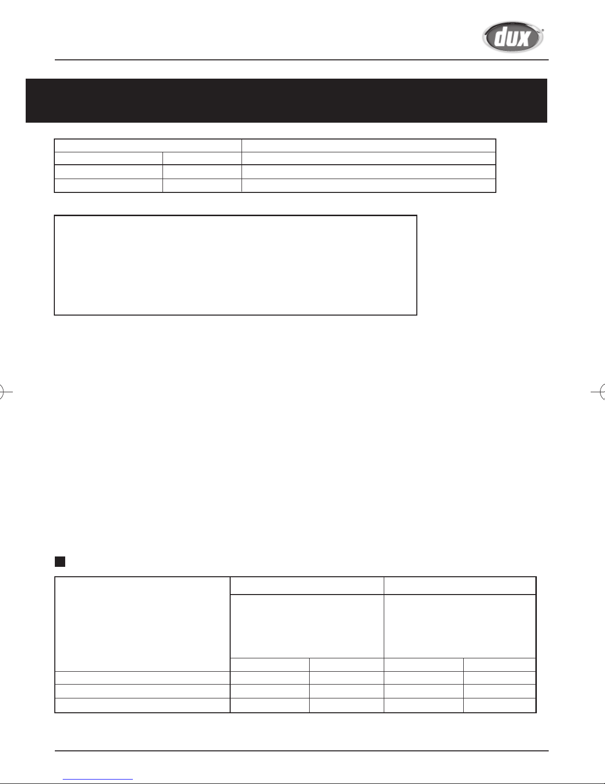
<The changing procedure of the maximum temperature setting.>
1.
Turn the water heater off by pressing the ON/OFF button on the remote controller.
2. Disconnect electrical power to the water heater.
3. Remove the front cover of the water heater (4 screws).
4.
Locate bridge attached to the inside of the front cover, and insert the bridge into plastic clip between the
remote controller terminals as shown on the right.
5. Replace the front cover of the water heater (4 screws).
6. Reconnect electrical power to the water heater.
21/26ENB serices and 17/21ECB series
Remote controller
Main controller
Bathroom controller
Bathroom 2 controller
ECM1D
ECB1D
ECB2D
55/60°C models
26ECB6N, 26ECB6L
21ECB6N, 21ECB6L
21ENB6N, 21ENB6L
17ENB6N, 17ENB6L
Factory Setting
37 - 55°C
37 - 50°C
37 - 50°C
Bridge in
37 - 60°C
37 - 50°C
37 - 50°C
26ECB5N, 26ECB5L
21ECB5N, 21ECB5L
21ENB5N, 21ENB5L
17ENB5N, 17ENB5L
Factory Setting
37 - 50°C
37 - 50°C
37 - 50°C
42/50
°C
models
Bridge in
37 - 42°C
37 - 42°C
37 - 42°C
23
Page 24
26ENA series
Installation Manual
Remote controller
Main controller
Bathroom controller
Bathroom 2 controller
ECM1D
ECB1D
ECB2D
55/60/75°C models
26ENA6N, 26ENA6L
Factory Setting
37 - 55°C
37 - 50°C
37 - 50°C
Bridge A
37 - 75°C
37 - 50°C
37 - 50°C
Bridge B
37 - 60°C
37 - 50°C
37 - 50°C
Factory Setting
37 - 50°C
37 - 50°C
37 - 50°C
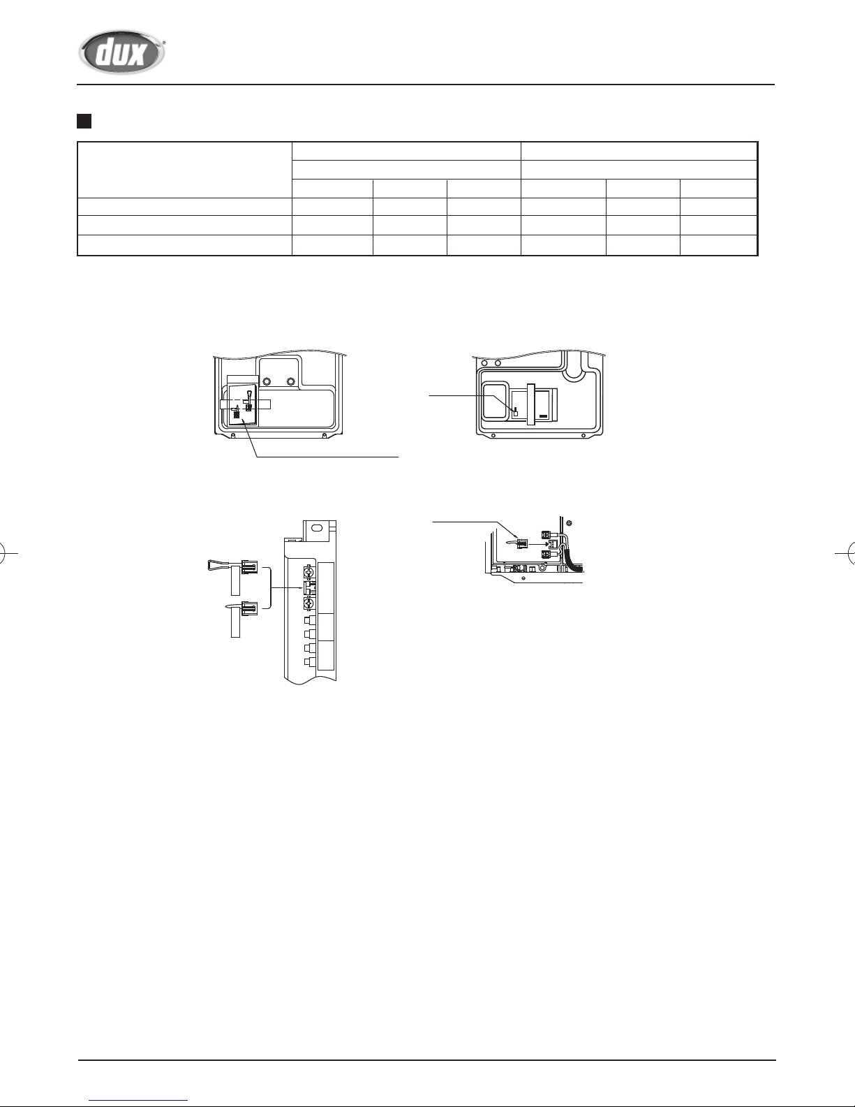
42/50
26ENA5N, 26ENA5L
26ENA series 21/26ECB series
17/21ENB series
A
B
Into Bridge A and Bridge B
Bridge
Bridge
°C
models
Bridge A
37 - 50°C
37 - 50°C
37 - 50°C
Bridge B
37 - 42°C
37 - 42°C
37 - 42°C
Bridge A
Bridge B
PCB
Remote
Controller
Adjust
Switch
Setting
Modulation
24
Page 25
Installation Manual
WARNING
• When changing the temperature, make sure to confi rm with the customer that the temperature of
the hot water will be very high and that there is a risk of scalding.
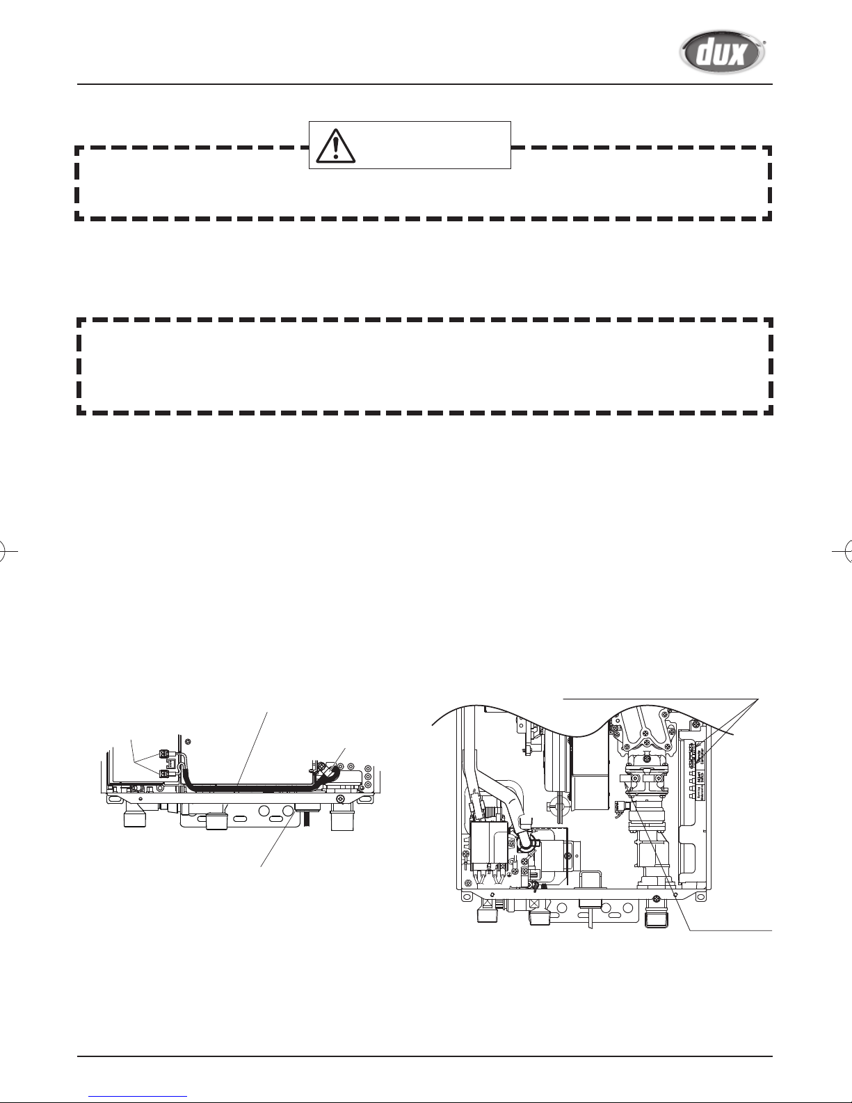
Connecting Remote Controller Cord to Unit
• Tie the excess cord outside the water heater. Do not put the extra length inside the water heater.
• The remote controller cord can be extended up to 35m.
• Be sure to hand tighten when screwing to the terminal block. Power tools may cause damage to the
terminal block.
Remote controller cord
• Use remote controller cord for any extensions.
• Install according to the National Electrical Code and all applicable local codes.
1. Disconnect electrical power to the water heater.
2. Leave enough slack so that the remote controller cord will not be damaged if the unit is removed from
the wall.
3. Remove the front cover of the heater (4 screws).
4. Pass the remote controller cord through the wiring throughway and into the unit.
5. Connect the Y terminals at the end of the remote controller cord to the terminal block.
6. Secure the remote controller cord with a clamp.
7. Replace the front cover.
Remote
Controller
Terminals
Remote Controller Cord
Cord Clamp
Wiring
Throughways
Remote Controller Terminals
26ECB series and 21ENB series
Cord Clamp
26ENA series
25
Page 26
Installation Manual
Maintenance
Periodically check the following to ensure proper operation of the water heater.
• The venting system must be examined periodically by a qualifi ed service technician to check for any
leaks or corrosion.
• The burner fl ame must be checked periodically for a proper blue colour and consistency.
• If the fl ame does not appear normal, the burner may need to be cleaned.
• If the burner needs to be cleaned, it must be performed by a qualifi ed service technician.
• Do not obstruct the fl ow of combustion and ventilation air.
See Owner's Guide for further maintenance or consult Dux Hot Water for recommended service checks.
•
Warning:
Should overheating occur, or the gas supply fail to shut off, turn off the manual gas control valve to the appliance.
Do not use this appliance if any part has been under water. Immediately call a qualifi ed service technician
Periodically check and clean the fi lter inside the cold water inlet of the unit.
There is a scald potential if the output temperature is set too high.
to inspect the appliance and to replace any part of the control system and any gas control which has been
under water.
Servicing by qualifi ed technician should be performed every two years.
Trial Operation
The installer should test operate the unit, explain to the customer how to use the unit, and give the owner
this manual before leaving the installation.
• Preparation ........... (1) Open a hot water fi xture to confi rm that water is available, and then close
the fi xture.
(2) Open the gas supply valve.
(3) Turn on the power supply. Using the remote controller, turn on the Power
ON/OFF button (the Operation lamp will turn on).
(1) Open a hot water fi xture and confi rm that the Burner on lamp comes on, and that hot water is being
produced. (If necessary, repeat until the air in the gas piping is bled out).
* White smoke may be noticed from the exhaust vent during cold weather. However, this is not a
malfunction of the unit.
* If an “11” error code appears on the remote controller, turn the unit off and then back on again,
and then open a hot water fi xture again.
(2) Change the temperature setting on the remote controller and check that the water temperature changes.
• If the water heater does not operate normally, refer to “Troubleshooting” in the Owner's Guide.
* After the trial operation, clean the fi lter in the cold water inlet.
Handling after trial operation
• If the unit will not be used immediately, close off all gas and water shut off valves, drain all of
the water out of the unit and the plumbing system to prevent the unit and system from freezing,
and bleed the gas out of the gas line.
Freezing is not covered by the warranty.
26
CAUTION
Page 27
Installation Manual
WARNING
A fi re or explosion may result if these instructions are not followed, which may cause lose of
life, personal injury or property damage.
Lighting Instructions
This water heater does not have a pilot. It is equipped with an ignition device that automatically lights the
burner.
Do not try to light the burner by hand.
1. Read the safety information in the installation manual or on the right side of the water heater.
2. Turn off all electrical power to the unit.
3. Do not attempt to light the burner by hand.
4. Turn the gas control manual valve (external to the unit) clockwise to the off position.
5. Wait fi ve minutes to clear out any gas. If the smell of gas remains, stop, and follow the instructions
on page 3 of Owner's Guide.
6. Turn the gas control manual valve counterclockwise to the on position.
7. Turn on electric power to the unit.
8. The unit will now operate whenever hot water is called for. If the unit will not operate, follow the shutdown instructions and call a service technician.
Shutdown Instructions
1. Stop any water demand.
2. Turn off electric power.
3. Turn the gas control manual valve clockwise to the off position.
Should overheating occur, or the gas supply fail to shut off, turn off the manual control valve to the appliance.
27
Page 28
Installation Manual
WATER QUALITY
All Dux water heating appliances are constructed from high quality materials and
components and all are certifi ed for compliance with relevant parts of Australian and New
Zealand gas, electrical and water standards.
Whilst Dux water heaters are warranted against defects, the warranty is conditional upon
correct installation and use, in accordance with detailed instructions provided with the
heater. In the case of the water supplied to the heater, it is important that the water quality
be of acceptable standard.
The water quality limits/parameters listed in water quality table are considered acceptable
and generally, Australian and New Zealand suburban water supplies fall within these
limits/parameters.
In areas of Australia and New Zealand where water may be supplied, either fully or partly,
from bores, artesian wells or similar, one or more of the important limits may well be
exceeded and the heater could, therefore, be at risk of failure.
Where uncertainty exists concerning water quality, intending appliance users should seek
a water analysis from the water supplying authority and in cases where it is established
that the water supply does not meet the quality requirements of the water quality table,
the Dux warranty would not apply.
WATER QUALITY TABLE
Maximum levels
pH Saturation Total Chlorides Sodium Iron
Index(LSI) Hardness
(langelier)
6.5-9 +0.4 to 200mg/l 250mg/l 180mg/l 1mg/l
Minus 1.0
@65C
28
 Loading...