

Dux 21ECB6N, 21ECB6L, 26ECB6N, 21ENB5N, 21ENB5L Installation Manual
...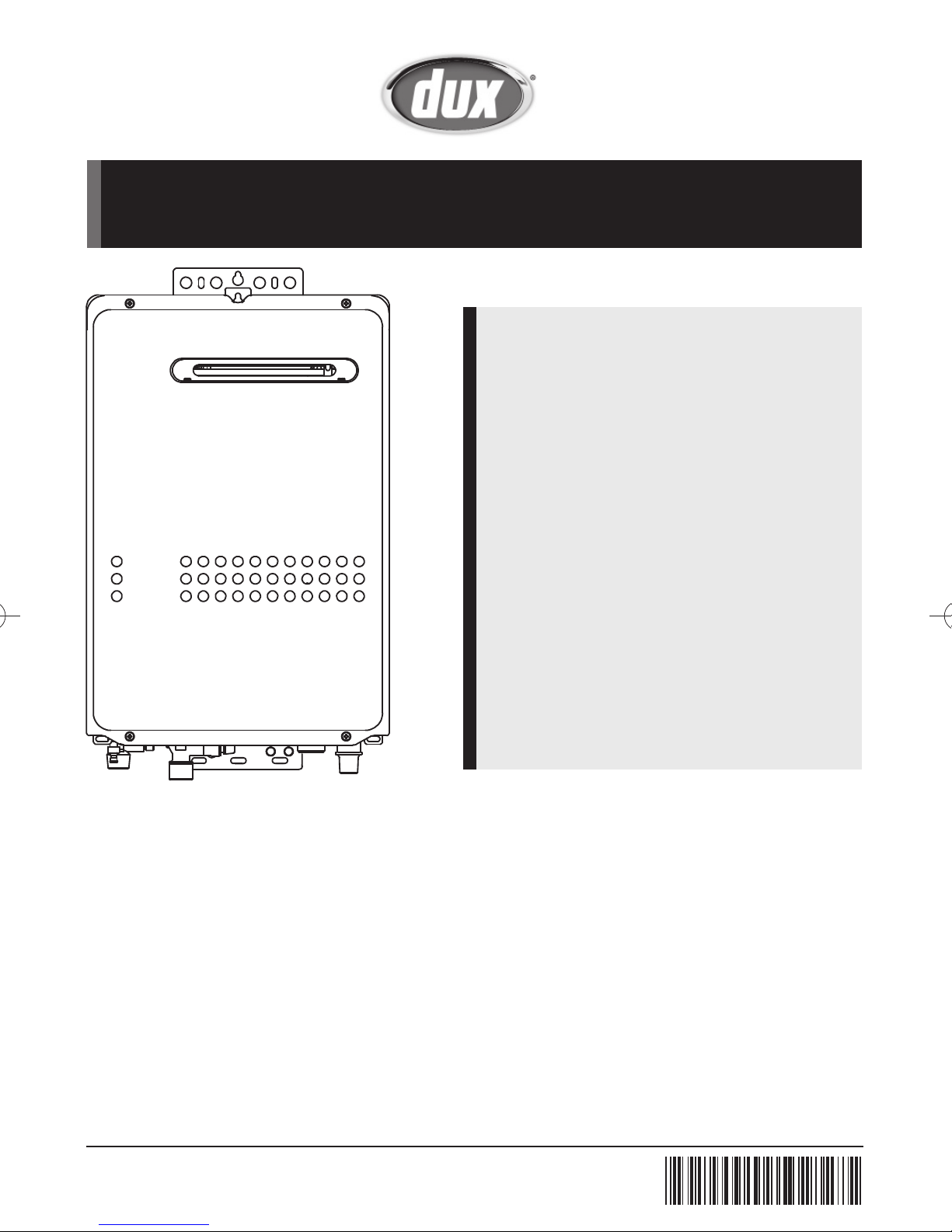
Installation Manual
Condensing Models
26ECB5N
26ECB5L
26ECB6N
26ECB6L
21ECB5N
21ECB5L
21ECB6N
21ECB6L
Non Condensing Models
21ENB5N 26ENA5N
21ENB5L 26ENA5L
21ENB6N 26ENA6N
21ENB6L 26ENA6L
17ENB5N
17ENB5L
17ENB6N
17ENB6L
Ex. 26ECB5N
To be installed and serviced only by an authorised person.
This appliance is not suitable for use as a pool heater.
The "authorised installing person" is responsible for:
1. Correct commissioning of this appliance
2. Ensure unit performs to the speci cation stated on the data label
3. Demonstrate operation of unit to customer before leaving
4. Hand these instructions to customer
This appliance must be installed in accordance with the manufacturer's installation instructions all Local Building,
Water and Gas tting regulations (AS/NZS3500.4, AS/NZS 5601, AS/NZS3000).
Failure to install this appliance in accordance with these installation instructions may void warranty.
In the interest of continued product improvement, Dux Manufacturing reserves the right to alter these speci cations
without notice.
SBB80PT
Rev. 06/16
AU Service Department : 1300 365 115
NZ Service Department : 0800 729 389
*SBB80PT*

Contents
1. Included Accessories ............................................................................. 4
2. Optional Accessories .............................................................................. 4
3. Dimensions ............................................................................................. 5
4. Component Details Example ................................................................ 9
5. Before Installation .................................................................................. 11
6. Specifi cations ......................................................................................... 12
7. Choosing Installation Site ..................................................................... 14
Installation Manual
8. Installation Clearances .......................................................................... 15
9. Installation .............................................................................................. 17
10. Gas Piping ............................................................................................... 18
11. Water Piping ........................................................................................... 19
12. Condensate Piping ................................................................................. 21
13. Electrical Wiring ..................................................................................... 22
14. Remote controller .................................................................................. 23
15. Maintenance ........................................................................................... 26
16. Trial Operation ........................................................................................ 26
WATER QUALITY .......................................................................................... 28
2
Installation Manual
Installation Manual
Condensing Models Non Condensing Models
26ECB5N
26ECB5L
26ECB6N
26ECB6L
Potential dangers from accidents during installation and use are divided into the following
three categories. Closely observe these warnings, they are critical to your safety.
DANGER
WARNING
CAUTION
WARNING:
causing property damage, personal injury or death.
If the information in this manual is not followed exactly, a fi re or explosion may result
21ECB5N
21ECB5L
21ECB6N
21ECB6L
21ENB5N
21ENB5L
21ENB6N
21ENB6L
DANGER indicates an imminently hazardous situation which,
if not avoided, will result in death or serious injury.
WARNING indicates a potentially hazardous situation which, if not
avoided, could result in death or serious injury.
CAUTION indicates a potentially hazardous situation which, if not
avoided, may result in minor or moderate injury.
17ENB5N
17ENB5L
17ENB6N
17ENB6L
26ENA5N
26ENA5L
26ENA6N
26ENA6L
Prohibited
Disconnect
Power
Earth
Be sure to do
CAUTION
Requests to Installers
• In order to use the water heater safely, read this installation manual carefully, and follow the
installation instructions.
• Failures and damage caused by erroneous work or work not as instructed in this manual are not
covered by the warranty.
• Check that the installation was done properly in accordance with this Installation Manual upon
completion.
•
After completing installation, please either place this Installation Manual in a plastic pouch and
attach it to the side of the water heater,
or hand it to the customer to retain for future reference.
CAUTION
• The water heater must be commissioned including checking gas supply pressures at maximum
demand.
•
The operation of the water heater should be explained including normal operation & regular
maintenance.
3
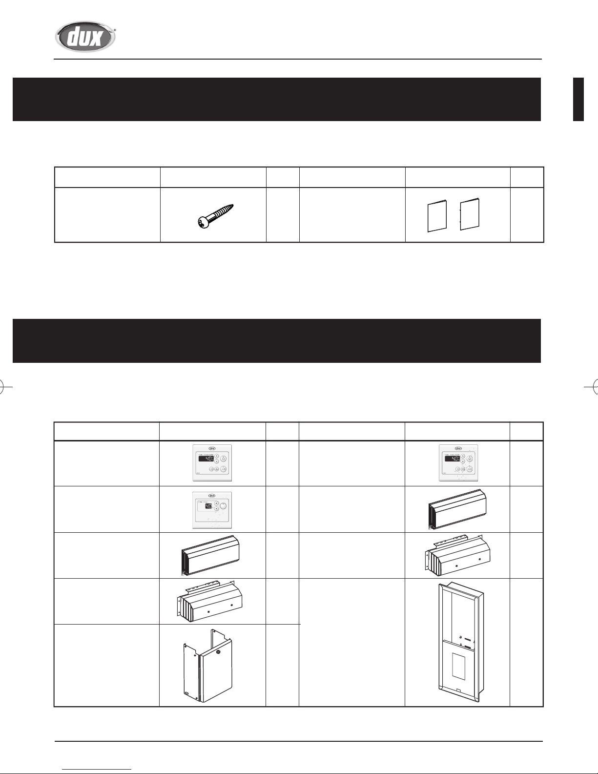
Included Accessories
The following accessories are included with the unit.
Check for any missing items before starting installation.
Installation Manual
Part Shape
Q’ty
Owner's Guide,
Anchoring Screw
5
Installation Manual
(this document)
Optional Accessories
The accessories listed below are not included with the units,
but may be necessary for installation.
Q’ty
Main Controller
(ECM1D)
MAIN
ECM1D
Bathroom Controller
1
(ECB1D)
ShapePart
Q’ty
1
each
ShapePartPart Shape
Q’ty
1
BATHROOM
ECB1D
Bathroom 2 Controller
(ECB2D)
Flue Diverter (L18)
for 26ENA series
Flue Diverter (L39)
for 17ENB series
Pipe cover
(H33-K-600)
• Maximum two Bathroom 2 controllers can be used. See P.23 for details.
4
ON/OFF
BATHROOM2
ECB2D
11
1
Flue Diverter (S37)
for 21/26ECB series
Flue Diverter (L38)
for 21ENB series
1
1
Recess Box (RBM2)
for 21/26ECB series,
17/21ENB series
1
1
Recess Box (RMM3)
for 26ENA series
Installation Manual
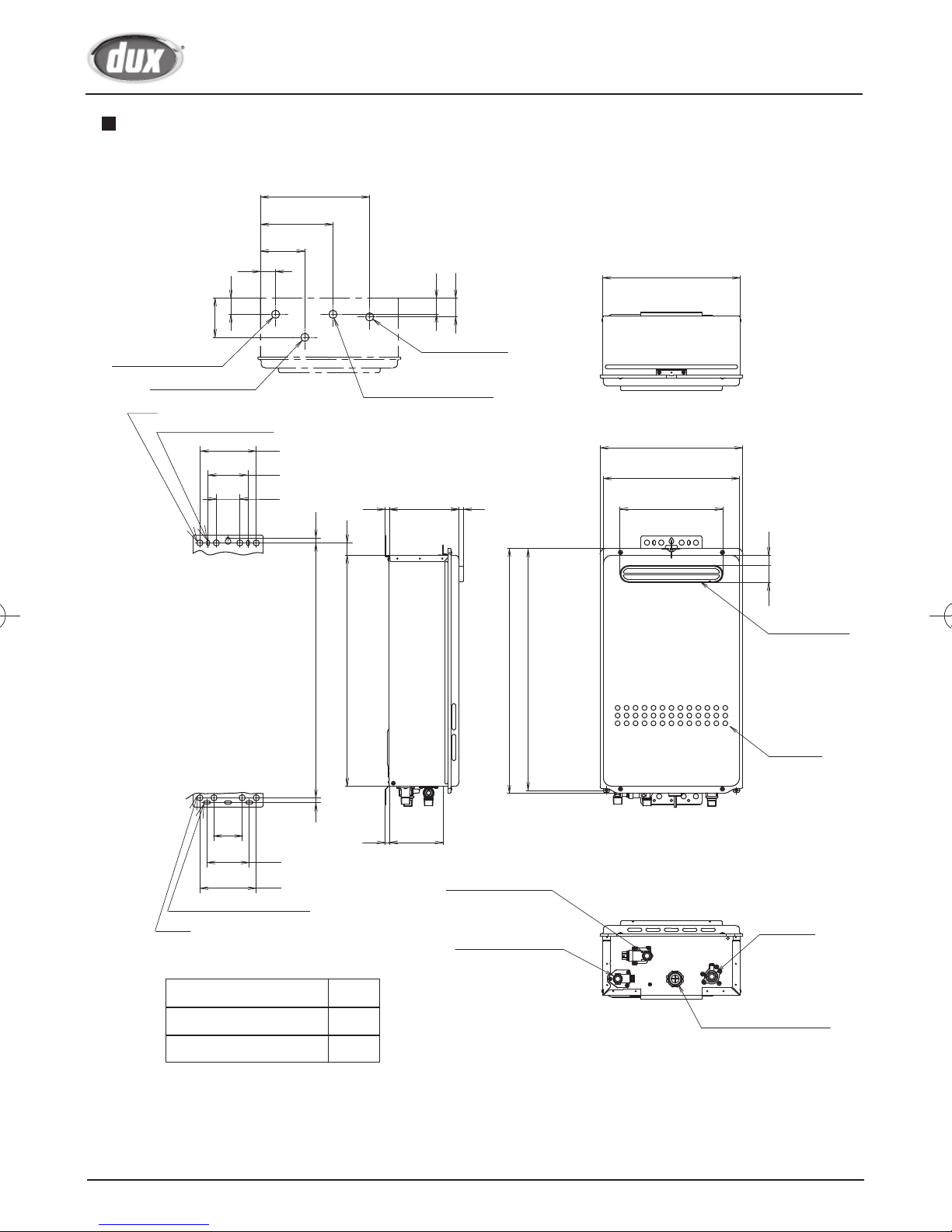
Dimensions
26ECB series
DRAIN OUTLET(R1/2)
45
87
HOT WATER OUTLET(R3/4)
COLD WATER INLET(R3/4)
4-φ13
2-6×13 OBLONG HOLE
(VIEW FROM TOP)
296
252
102
96
30
21
120
85
50
10
31
GAS INLET(R3/4)
WIRING THROUGHWAYS
10
<Unit : mm>
40
97
170
27
11
338
350
334
217 28
56
2-6.5×16.5 OBLONG HOLE
4-φ13
120
28
486
54210
487
60
90
10 AIR INLET
NEUTRALIZER TANK DRAIN
HOT WATER OUTLET
HEIGHT OF EACH FITTING
FROM BOTTOM OF CASE
DRAIN OUTLET
520
AIR INLET
30
FLUE EXHAUST
AIR INLET
COLD WATER INLET
WIRING THROUGHWAYS
GAS INLET
DRAIN OUTLET
HOT WATER OUTLET 45
COLD WATER INLET 58
GAS INLET 50
5
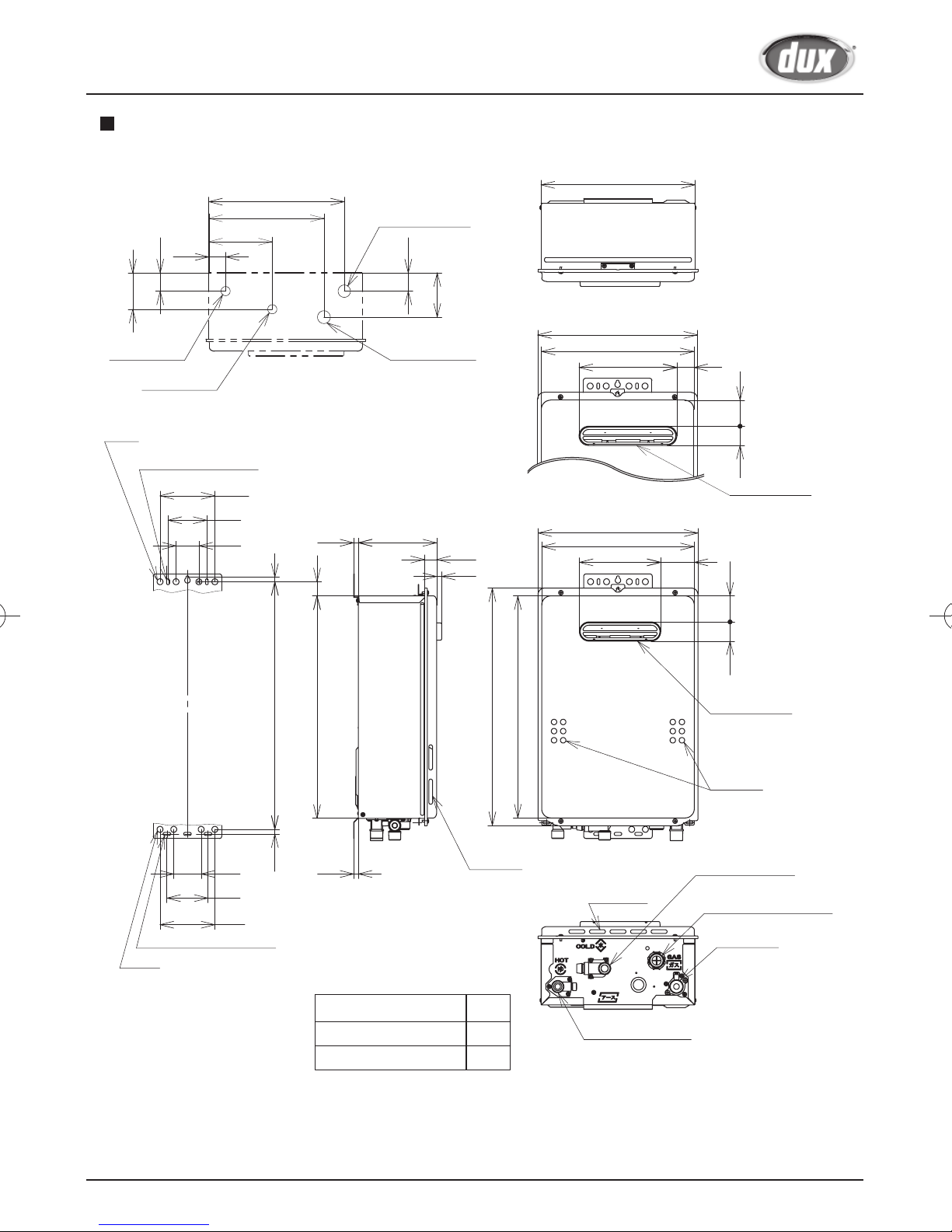
26ENA series
Installation Manual
(VIEW FROM TOP)
268
178
109
37
40
97
47
40
338
<Unit : mm>
HOT WATER OUTLET(R3/4)
COLD WATER INLET(R3/4)
4-φ13
2-6×13 OBLONG HOLE
120
85
50
GAS INLET(R3/4)
WIRING THROUGHWAYS
350
334
10 11
10
31
567
62210
170
600
566
253
42 25
FLUE EXHAUST
AIR INLET
60
84
120
3-6.5×16.5 OBLONG HOLE
4-φ13
HEIGHT OF EACH FITTING
FROM BOTTOM OF CASE
HOT WATER OUTLET 44
COLD WATER INLET 48
GAS INLET 49
6
10 133
COLD WATER INLET
GAS INLET
HOT WATER OUTLET
WIRING THROUGHWAYS
Installation Manual
17/21ENB series
37
40
80
HOT WATER
OUTLET(R3/4)
COLD WATER
INLET(R3/4)
4-φ13
2-6ᨴ13 OBLONG HOLE
᧤VIEW FROM TOP᧥
296
252
139
120
85
50
10542
<Unit : mm>
GAS INLET(R3/4)
40
97
338
21ENB Series
350
WIRING
THROUGHWAYS
334
214 37
42 57
FLUE EXHAUST
17ENB Series
10
31
170
27
11
350
334
178
73
60
90
120
3-6.5ᨴ16.5 OBLONG HOLE
4-φ13
487
10
10
HEIGHT OF EACH FITTING
FROM BOTTOM OF CASE
HOT WATER OUTLET
COLD WATER INLET
GAS INLET
520
AIR INLET
45
48
50
486
AIR INLET
HOT WATER OUTLET
42 57
FLUE EXHAUST
AIR INLET
COLD WATER INLET
WIRING THROUGHWAYS
GAS INLET
7
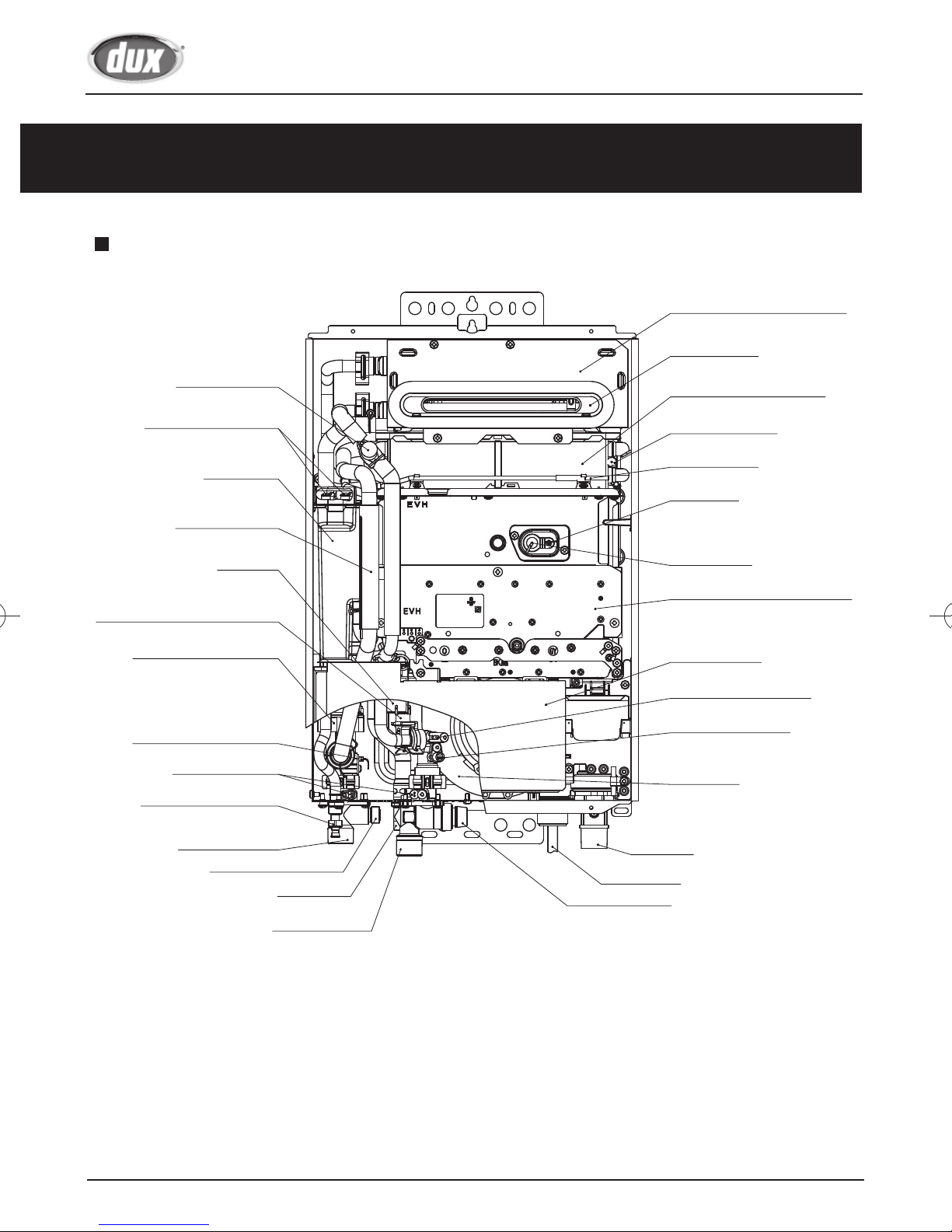
Component Details Example
26ECB series model shown for illustration only
Installation Manual
Secondary heat exchanger
Flue exhaust
High limit switch
Water level electrode
Neutralizer
Anti-frost heater
Igniter
Freeze protection thermostat
Main flow control valve
Water outlet thermistor
Anti-frost heater
Neutralizer tank drain
Primary heat exchanger
Anti-frost heater
Thermal fuse
Flame rod
Ignition plug
Burner manifold & gas valve
Circuit board
Water inlet thermistor
Water flow sensor
Fan motor
Hot water outlet
Pressuer relief valve
Drain outlet
Cold water inlet
8
Gas inlet
Power code
Inlet water filter
Ex. 26ECB5N
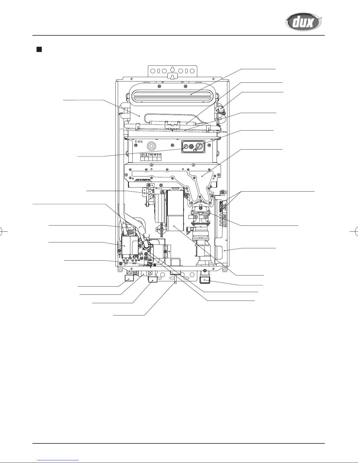
Installation Manual
26ENA series model shown for illustration only
Heat exchanger
Flame rod
Flue exhaust
Anti-frost heater
High limit switch
Thermal fuse
Ignition plug
Burner manifold
Igniter
Freeze protection thermostat
Main flow control valve
Earth leakage breaker
Anti-front heater
Hot water outlet
Inlet water filter
Cold water inlet
Remote Control Connections
Gas solenoid valve set
Circuit board
Fan motor
Gas inlet
Water inlet thermistor
Water flow sensor
Power code
Ex. 26ENA5N
9
 Loading...