

Dux 135ZB4N, 135ZB4P, 170ZB4P, 170ZB4N Owner's Manual

Owner’s Manual
Models: 135ZB4N / 135ZB4P
170ZB4N / 170ZB4P
4 Star Gas Hot Water Heater
Specications and materials may change without notice.
Effective for all Prodigy 4 water heaters manufactured and sold after 1st July 2016.
For advice, repairs and service, call:
1300 365 115 (Australia)
0800 729 389 (New Zealand)
Carefully remove all packaging and
transit protection from the heater before
installation. Dispose of the packaging
responsibly using re-cycling facilities
where they exist.
Installation Details
Owner’s Information
Warranty
H3071 3071 Rev. K

Owner’s Manual – Prodigy 4
H3071 3071 Rev. K
Contents
Installation Requirements 1
Specications 4
Plumbing Connections 5
Gas Connection and Filling 7
Lighting the Water Heater 8
Shut Down and Draining 9
Testing 10
Owner’s Information 11
System Maintenance 13
Considering a Service Call? 14
Warranty 15
© Dux Manufacturing Limited 2016. All rights reserved.

Owner’s Manual – Prodigy 4
1
H3071 3071 Rev. K
Installation Requirements
General:
This water heater must be installed
by a licensed tradesperson, and in
accordance with:
• AS/NZS 3500.4 Plumbing and
Drainage – Heated Water Services.
• Clause G12 of the NZ Building
Code (in New Zealand).
• AS/NZS 5601.1 Gas Installations –
General Installations.
• Local authority regulations.
• Outside Australia and New Zealand,
please refer to local plumbing and
building codes and regulations.
Failure to comply with these
requirements may affect your warranty.
Note for Victoria:
This water heater must be installed by
a licensed person as required by the
Victorian Building Act (1993).
Only a licensed person will provide a
compliance certicate, showing that
the work complies with all the relevant
Standards. Only a licensed person
will have insurance protecting their
workmanship.
Pool Heating:
This water heater must not be used for
pool heating.
Location:
The water heater must be installed
outdoors.
The water heater should be located as
close as possible to the most frequently
used hot water outlet while still
complying with the clearances specied
in clause 6.9 of AS/NZS 5601.1.
See Clearances on page 2 for further
information.
Ensure that the compliance plate and
associated warnings are clearly visible.
Adequate access must be available for
service to the gas controls, relief valve
and anode.
The water heater must not be installed
below ground level or in a location
where water pools. The water heater
must be accessible without the use of a
ladder or scaffold.
The water heater must be installed
upright with its back against an external
wall.
Note - all models are equipped with a
sacricial anode, accessible through
the top cover. It is recommended that
a distance of 50% of the height of the
water heater is provided as clearance
above the water heater. This will assist in
the replacement of the anode.
Owner’s Manual – Prodigy 4
2
H3071 3071 Rev. K
Installation Requirements
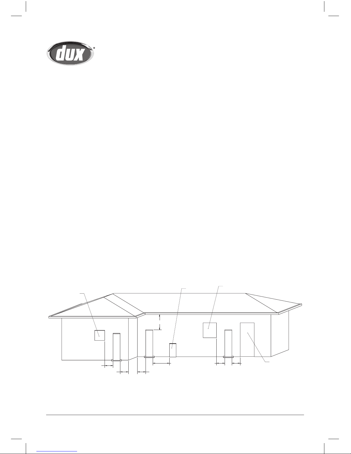
Clearances:
Clause 6.9 of AS/NZS 5601.1 species
the minimum clearances required
between the water heater and building
features, structures and other items.
As a guide, some of the common
clearance requirements are set out
below:
• At least 300 mm below any eaves,
balconies or other projections.
Note that at least half the height of
the water heater is recommended
as clearance to provide access to
the anode.
• At least 500 mm from any external
corner.
• At least 500 mm from any return
wall or other structure facing the
side of the water heater.
• At least 1000 mm from any gas
meter.
• At least 500 mm from any electricity
meter or fuse box.
• At least 500 mm from any openable
window or door.
For a full list of the requirements and
exemptions please refer to
AS/NZS 5601.1.
1000mm MIN
500mm MIN
500mm MIN
500mm MIN
300mm MIN
500mm MIN 500mm MIN
ELECTRICITY METER
OR FUSE BOX
WINDOW OR
OTHER OPENING
DOOR
GAS METER

Owner’s Manual – Prodigy 4
3
H3071 3071 Rev. K
Installation Requirements
Water Heater Support:
The water heater must be installed on a
at, solid, non-combustible supporting
surface. The weight of the water heater
should not cause deformation to any
part of the building structure.
It is recommended that a plinth is
installed under the water heater.
The water heater must be installed
plumb and level.
The water heater must also be secured
to a durable structure using the wall
brackets supplied loose with the water
heater. Note that the gas or water
pipework must not be used to support
the water heater.
The wall brackets are designed to be
installed on each side of the water
heater with the long leg against the side
of the water heater and the short leg
against the wall. The brackets should be
located near the top of the water heater,
approximately in line with the Outlet
and Relief Valve sockets. Note that
once installed, the brackets should not
obscure any labels on the water heater.
The brackets should be xed to the wall
with suitable fasteners and xed to the
water heater with the self drilling screws
provided.
Water Supply:
This water heater has been
manufactured to suit the water
conditions of most Australian
metropolitan supplies.
Please note that certain water supplies
can have a detrimental effect on the
water heater and its life expectancy. If
you are unsure about the water supply
you can obtain information from the
local water supply authority.
The water heater is designed for use in
areas where the Total Dissolved Solids
(TDS) content of the water supply is
less than 2500 mg/L. The Tank Failure
Warranty does not apply in areas where
the TDS exceeds 2500 mg/L.
In areas where the TDS exceeds
600mg/L it is possible that the
magnesium alloy anode (supplied in
standard water heaters) may become
overreactive. To alleviate this, the
magnesium anode should be replaced
with an aluminium alloy anode.
Aluminium alloy anodes are available
from your local Dux Supplier.
Water can also be very corrosive, the
measure of this is the saturation index.
If the water saturation index is greater
than 0.40, an expansion control valve
should be tted. Please consult Dux
After Sales and Service for advice if
required.
Owner’s Manual – Prodigy 4
4
H3071 3071 Rev. K
Specifications
Specifications 135ZB4N 135ZB4P 170ZB4N 170ZB4P
Capacity (L) 135 135 170 170
Gas Type Natural Gas Propane Natural Gas Propane
Net Weight Empty (kg) 72 72 86 86
Relief Valve Pressure (kPa) 1400 1400 1400 1400
Gas Consumption (MJ/h) 29.5 28 33.5 32
Injector Size (mm) 2.35 1.35 2.55 1.50
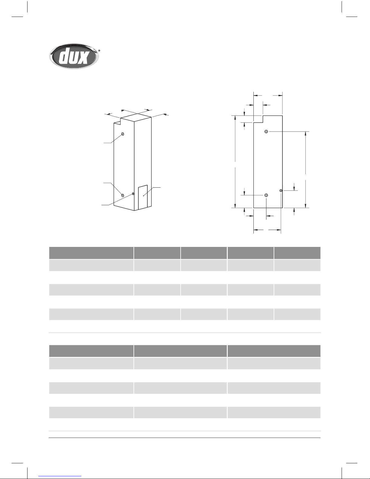
Nominal Dimensions 135L 170L
A – Overall Height (mm) 1600 1895
B – Outlet Height (mm) 1325 1620
C – Inlet Height (mm) 220 220
D – Gas Entry Height (mm) 300 300
E – Inlet/Outlet Offset (mm) 220 220
F – Gas Entry Offset (mm) 475 475
340
422
ACCESS COVER
HOT WATER OUTLET
COLD WATER INLET
GAS ENTRY HOLE
PTR SOCKET ON
RIGHT HAND SIDE
A
D
C
B
120
E
F
162
502
 Loading...