

Page 1
®
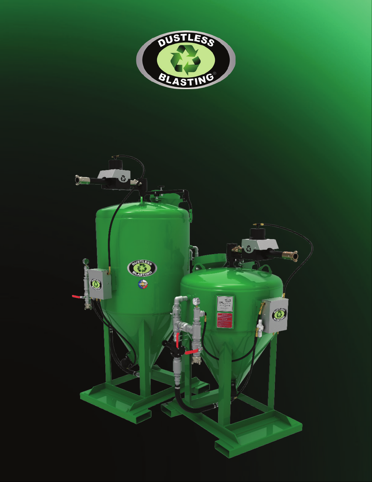
DB1500/DB3000
USER MANUAL
®
Page 2
The Future of Surface Preparation
®
MMLJ, INC.
5711 Schurmier Rd.
Houston TX, 77048
800-727-5707
Toll Free
+1 713-869-2227
International
Email
713-868-8041
Fax
Facebook.com/DustlessBlaster
Youtube.com/MMLJManufacturing
@DustlessBlaster
Dustless_Blasting
Page 3

A NOTICE TO INTERNATIONAL DISTRIBUTORS:
International Distributors are responsible for
translation of the manual.
Please read and understand manual fully prior
to operating any machinery.
TABLE OF CONTENTS
Warning I
Warranty II
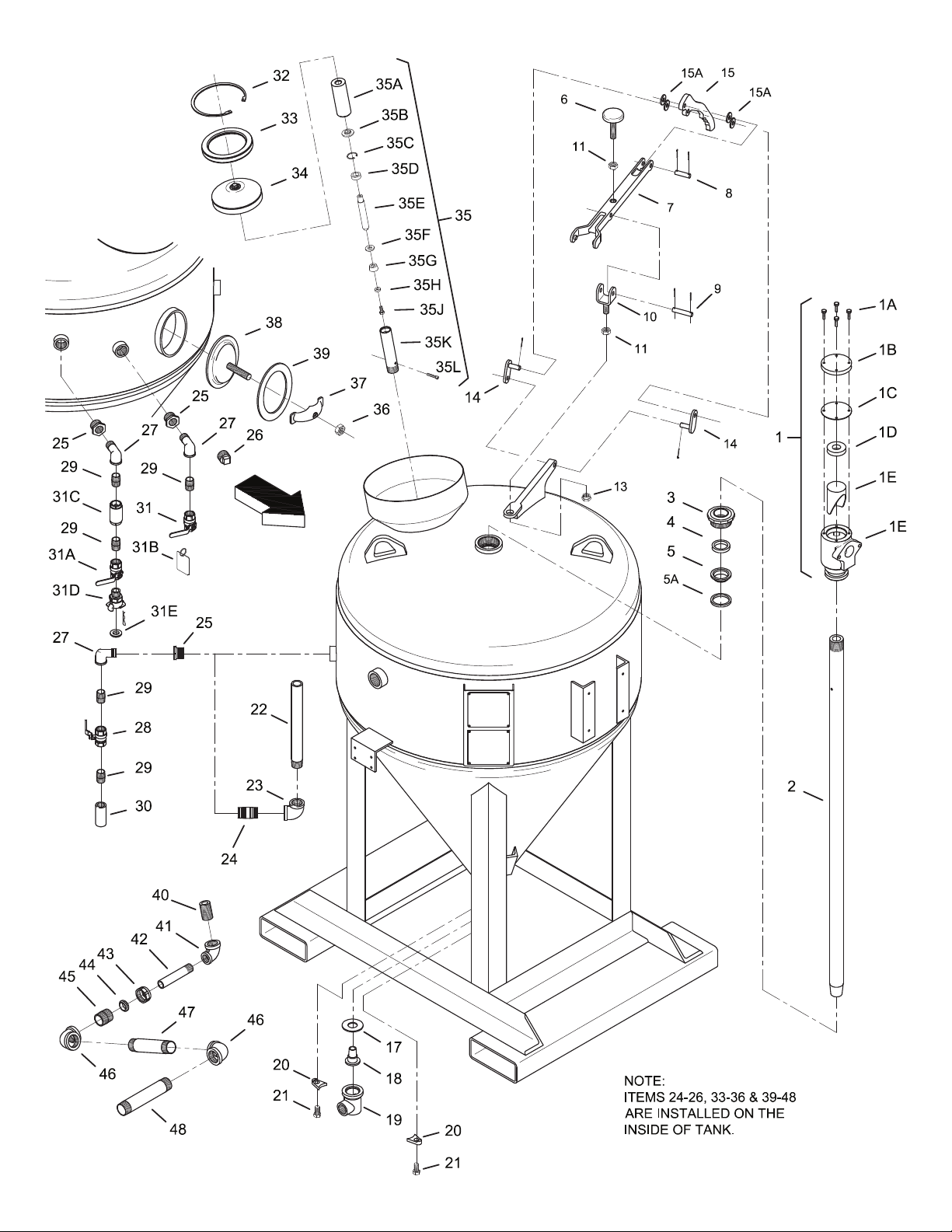
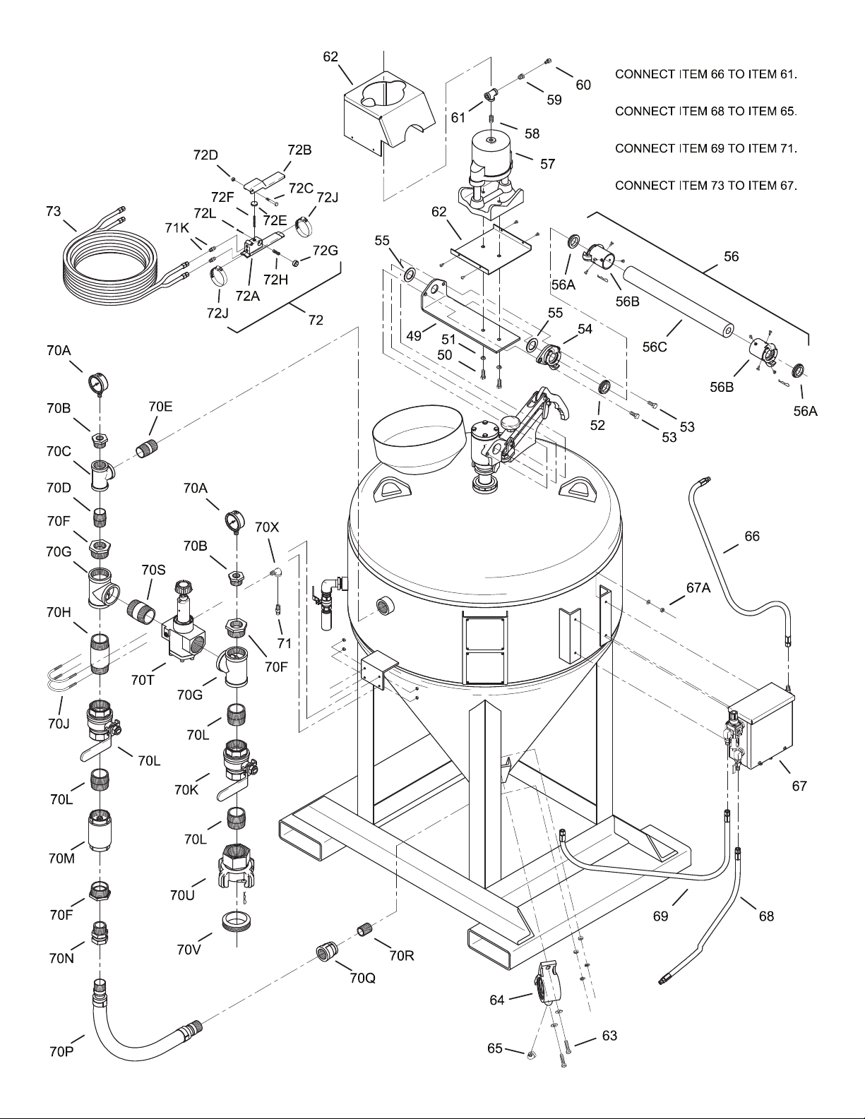
Diagrams and Part Lists
DB1500® Model 1
DB3000® Model 2
DB1500® – DB3000® Diagram 3
DB1500® – DB3000® Parts List 5
Start Up and Shut Down Procedures
Getting Started 9
Shut Down Procedures 10
Maintenance and Best Practices
Maintaining your Blast Pot 11
Troubleshooting 13
Containment, Masking, and Nozzle Control 14
Switching from Wet Blasting to Dry Blasting 14
Storing Machine 15
Choosing Your Blast Pressure 16
Choosing Your Abrasive 17
Abrasive Comparison Chart 19
Resources and Training 20
Page 4

IMPORTANT
(Pertinent to blast machines)
WARNING
Before operating any abrasive blast cleaning equipment
READ ALL operating and maintenance instructions.
Personal protective equipment is REQUIRED when using
this type of equipment. Operator MUST be equipped with
heavy canvas or leather gloves, aprons, and arm protectors.
Safety shoes and hearing protection MUST be worn when
required. NIOSH approved air fed respirators (helmets)
furnished with at least Grade D breathing air MUST be used
for protection against dust inhalation. Air MUST be ltered
and monitored for Carbon Monoxide.
DANGER.
Use of Abrasive cleaning equipment with silica sands may
produce a heavy concentration of silica dust. Breathing this
dust can produce “Silicosis”, a permanent lung disease.
Depending upon the object to be cleaned, blasting, even
with non-silica abrasives, may release hazardous dust
particles into the air that can cause permanent lung
damage. Failure to use NIOSH approved air fed respirator
(helmet) may cause SERIOUS lung DAMAGE. This warning,
as to the proper use of an approved respirator (helmet),
applies not only to the operator, but extends to all those
working in or around the blasting area, such as pot tenders,
painters, supervisors, etc.
CAUTION
Blast cleaning equipment and components are subjected to
wear and deterioration.
• Keep your equipment in good operable condition.
• MAINTAIN nozzle control at all times during operation.
• INSPECT machine, nozzles, hoses, and couplings.
• Inspect, clean, or replace helmet lens and lters frequently.
• Ground equipment to AVOID electrical shock.
• DO NOT operate any machine without thorough knowledge
of machine operation.
Carefully READ the INSTALLATION, OPERATING, AND
MAINTENANCE directions supplied with the machine from
the factory. If you do not have a copy, please contact your
employer (supervisor) or MMLJ Inc.
IMPORTANTE
(Relativo a todos maquinas)
ADVERTENCIA
Antes de operar cualquiera de los equipos de limpieza con
chorro abrasivo, LEA TODOS las instrucciones de operacion
y mantenimiento. ES OBLIGATORIO usar equipo protector
personal al manejar este tipo de equipos. El Operador
DEBE. estar equipado con guantes, delantales y protectores
de brazos de cuero 0 Iona pesada. DEBEN usarse zapatos
de seguridad y proteccion para los oldos cuando aSI se
exija. Los respiradores (cascos) alimentados por aire,
aprobados por NIOSH y que esten previstos de por 10
menos aire respi rable de Grado D, DEBEN ser usados como
proteccion contra la inhalacion de polvo. El aire DEBE ser
ltrado y controlado para detectar monoxide de carbono.
PELIGRO
Es posible que el uso de los equipos de limpieza por
abrasion con arenas sillceas provoque una concentracion
pesada de polvo sillceo. Este polvo, al ser respirado,
puede producir “silicosis”, que es una enfermedad
pulmonar permanente. Dependiendo del objeto que va
a limpiarse, es posible que la limpieza a chorro, aun con
abrasives no silfceos, provoque el escape de partlculas
de pohio pel igrosas en el aire que pueden causar dano
pulmonar permanente. Si nose usan los respiradores
(cascos) alimentados por aire, aprobados por NIOSH,
puede provocarse un GRAVE DANO a los pulmones. Esta
advertencia sabre el uso adecuado de un respirador (casco)
aprobado no solo se aplica al operador sino que comprende
a todos aquellos que trabajan en el area de limpieza a
chorro, 0 al rededor de la misma, como por ejemplo los que
vigilan los recipientes, los
pintores, supervisores, etc.
PRECAUCION
El equipo de limpieza a chorro y sus componentes estan
sujetos a desgaste y deterioro.
• Mantenga su equipo en buenas condiciones deoperacion,
• MANTENGA el control de la boquilla en todo momenta
durante la operacion.
• INSPECCIONE !a maquina, las boquillas, las mangueras y
las uniones.
• ALAMBRE juntas todas las uniones de la manguera de
rapido ajuste.
• lnspeccione, limpie 0 reemplace los lentes y ltros del
casco frecuentemente.
• Conecte el equipo a tierra para EVITAR un shock electrico.
• NO opere ninguna maqu ina sin tener un detallado
conocimiento de la operacion de la misma.
LEA cuidadosamente las instrucciones de INSTALACION,
OPERACION Y MANTENIMIENTO que vienen incluidas
de fabrica con la maquina. Si no tiene una copia, slrvase
comunicarse con su empleador (supervisor) con MMLJ Inc.
I
Page 5

BLAST POT WARRANTY
MMLJ, INC. LIMITED WARRANTY
IMPORTANT: Terms of Warranty
MMLJ, Inc. warrants that the product you have purchased is free from defects in materials or workmanship under normal use during the
warranty period. Your sales receipt, showing the data of purchase for this product, is your proof of the date of purchase. This warranty
is valid only if the product is assembled/installed according to the instructions included with the product.
During the warranty period, MMLJ, Inc. will repair or replace (at MMLJ, Inc.’s option) the product if it becomes defective or otherwise
fails to conform to this Warranty under normal use. In repairing the product, MMLJ, Inc. may replace defective part with new, or at the
option of MMLJ, Inc., serviceable used parts that are equivalent to new parts in performance. MMLJ, Inc. reserves the right to change
manufacturers of any part to cover any existing warranty. This extends to items normally covered by a manufacturer other than MMLJ,
Inc. used on this product within the rst calendar year of purchase.
This warranty does not cover shipping charges; export taxes, custom duties and taxes, or any other charges associated with
transportation of the parts or products. To obtain warranty service, you must contact MMLJ, Inc.’s customer service representative.
Any parts determined to be defective must be brought to the attention of MMLJ, Inc. within 6 months of delivery of equipment. You
must prepay any shipping charges, export taxes, custom duty taxes, or any other charges associated with transportation of the parts or
product. In addition, you are responsible for insuring any parts or product shipped or returned. You assume the risk of loss during the
shipment. You must present MMLJ, Inc. with proof-of-purchase documents (including the date of purchase). Any evidence of alteration,
erasure, or forgery of proof-of-purchase documents will be cause to void this warranty.
The warranties listed above do not extend to any product that has been damaged or rendered defective (a) as a result of accident,
misuse, or abuse (b) by the use of parts not manufactured or sold by MMLJ, Inc. and/or (c) by modication or improper installation of
the product. Product on which the serial number has been defaced or removed is not eligible for warranty service. Should any product
submitted for warranty service be found ineligible, an estimate of repair cost will be furnished and the repair will be made if requested
by you upon MMLJ receipt of payment or acceptable arrangements for payment. Except, as expressly set forth in this warranty, MMLJ
makes no other warranties, expressed or implied. This is the only express warranty applicable to Dustless Blasting® branded products.
MMLJ does not assume, nor authorize anyone to assume for it any other express warranty.
BLAST POT, LIMITED LIFETIME WARRANTY:
This warranty applies only to pressure vessels manufactured by MMLJ, Inc. under the Dustless Blasting® brand name. This product is
backed by a limited lifetime warranty, excluding only expendable parts such as gauges and valves (which are covered by manufacturer
other than MMLJ, Inc.) and paint.
This Limited Warranty does not extend to any product that has been damaged or rendered defective (a) as a result of accident, misuse,
or abuse (b) by the use of parts not manufactured or sold by MMLJ, Inc. and/or (c) by modication or improper installation of the
product.
IMPORTANT: Third Party Warranties
For parts that are not covered by MMLJ, Inc., please contact our ofce and report the defect. MMLJ, Inc. will then proceed with the
warranty process for the affected item on your behalf. All items not covered by MMLJ, Inc. will fall under a limited one year warranty
free of manufacturer defects.
For more warranty information, visit www.DustlessBlasting.com/legal/warranties.
Please call our ofce for any questions on warranties or warrantied items.
Toll Free: 800-717-5707
International: +1 713-869-2227
[email protected]
II
Page 6
INSTALLATION AND
OPERATING INSTRUCTIONS
PLEASE READ CAREFULLY BEFORE OPERATING
14
1
17
9
10
4
5
7
6
8
15
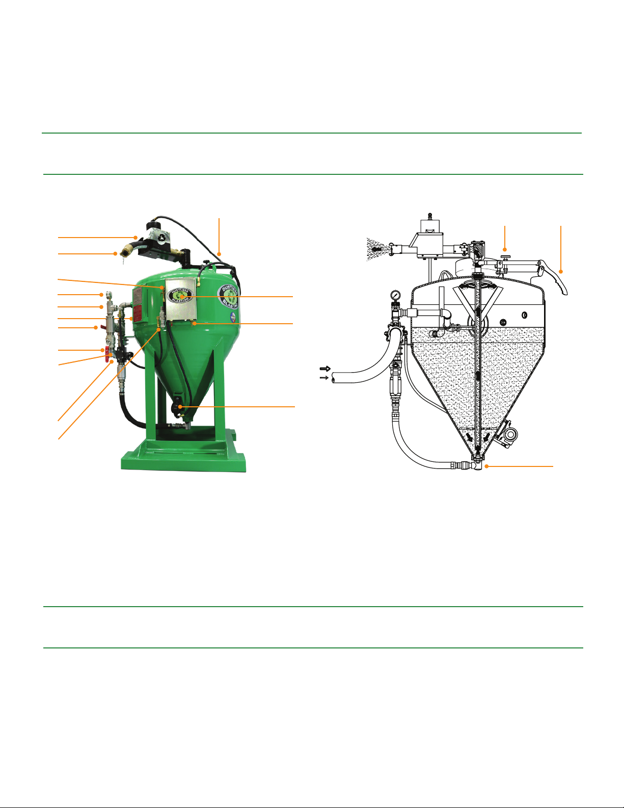
MODEL DB1500® FIGURES
1. Pinch Hose
2. Control Box Input Couplings
3. Fill Port
4. Blowdown Valve (Located on opposite side)
5. Air Inlet Valve
6. Compressed Air Inlet
3
18
2
16
7. Popup Gasket Valve
8. Pressure Regulator
9. Compressed Air Pressure Gauge
10. Blast Pressure Gauge
11. Abrasive Control Lever
12. Abrasive Control Knob
13. Bottom Flange
14. Pinch Valve
15. Moisture Trap
16. Vibrator
17. Vibrator Valve
18. Control Box
12
11
13
Carefully read the INSTALLATION, OPERATING, and MAINTENANCE directions supplied with the machine from the factory.
If you do not have a copy, please contact your employer (supervisor) or the MMLJ Inc. Company.
This system will mix clean water, rust inhibitor, and abrasive together. The DB1500
• 75 gallons of clean water
• 750 lbs of Abrasive, mesh size approx. 50/70
• 100 oz of Rust Inhibitor
1
®
is designed to hold:
Page 7
INSTALLATION AND
OPERATING INSTRUCTIONS
PLEASE READ CAREFULLY BEFORE OPERATING
10
3
2
4
8
14
1
1112
9
17
18
15
7
6
5
16
13
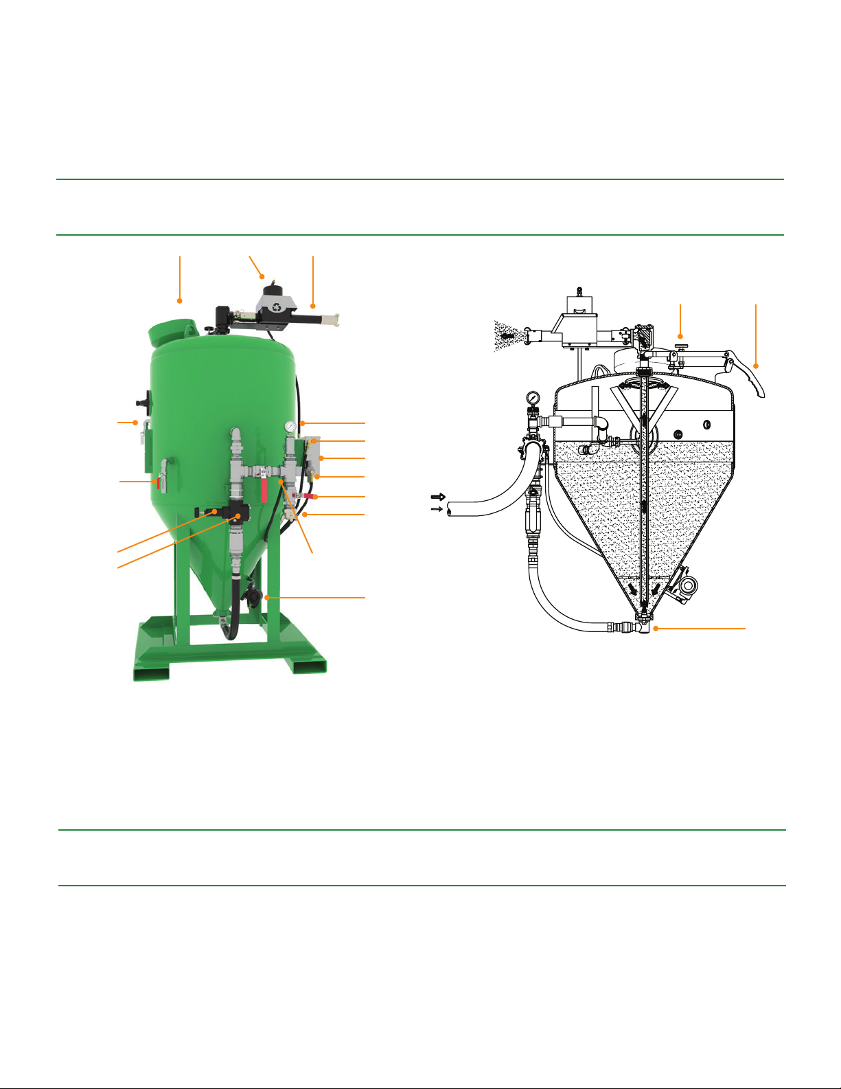
MODEL DB3000® FIGURES
1. Pinch Hose
2. Overow Valve
3. Fill Port
4. Blowdown Valve
5. Air Inlet Valve
6. Compressed Air Inlet
Carefully read the INSTALLATION, OPERATING, and MAINTENANCE directions supplied with the machine from the factory.
If you do not have a copy, please contact your employer (supervisor) or the MMLJ Inc. Company.
This system will mix clean water, rust inhibitor, and abrasive together. The DB3000
• 150 gallons of clean water
• 1.5 gallons of Rust Inhibitor
• 1500 lbs of Abrasive, mesh size approx. 50/70
7. Popup Gasket Valve
8. Pressure Regulator
9. Compressed Air Pressure Gauge
10. Blast Pressure Gauge (Behind Regulator)
11. Abrasive Control Lever
12. Abrasive Control Knob
2
13. Bottom Flange
14. Pinch Valve
15. Moisture Trap
16. Vibrator
17. Vibrator Valve
18. Control Box
®
is designed to hold:
Page 8
346
Page 9
Page 10

Page 11

Item No. Description Part No. Stock No. Qty.
1
1A
1B
1C
1D
1E
1F
5A
10
11
12
13
14
15
16
17
18
19
20
21
22
22
23
24
25
26
27
28
29
30
31
31A
31B
31C
31D
31E
32
33
34
35
35A
35B
35C
35D
35E
35F
35G
35H
35J
35K
Outlet Elbow Assembly Complete M-17 72974/001 1
Outlet Elbow Cap Bolts (4) M-17-D 82563/001 1
Outlet Elbow Cap M-17-C 131054/001 1
Outlet Elbow Cap Gasket M-17-G 131227/001 1
Outlet Elbow Insert Gasket M-23-G 131147/001 1
Outlet Elbow Insert M-23 73602/001 1
Outlet Elbow Body M-17-B 80789/001 1
2
52" Outlet Pipe (DB-1500) 134708/001 1
2
74" Outlet Pipe (DB-3000) 134703/001 1
3
Packing Gland Nut M-5-1 131102/001 1
4
Gasket M-13 131226/001 1
5
Gasket M-5-G 131225/001 1
Seal (manufactured after 5/15/13) M-6-S 131226/002 1
6
Rocker Arm Adjusting Screw AB-8 73464/001 1
7
Rocker Arm (long) B-3-1L 73480/003 1
8
Abrasive Lever Clevis Pin w/ Cotter Pins AB-11-S 131070/001 1
9
Pedestal Clevis Pin w/ Cotter Pins AB-12-S 131069/001 1
Rocker Arm Hinge Yoke AB-75 131113/001 1
Rocker Arm Yoke/Rocker Arm Adjusting Screw Locking Nut AB-75-C 22926/001 2
Rocker Arm Acorn Nut (5/8"-11) AB-8-N 134687/002 1
Rocker Arm Hinge Yoke Adjusting Nut AB-75-E 131094/001 1
Connecting Link w/ Cotter Pin AB-10 131133/0 2
Abrasive Control Lever AB-9 73500/001 1
Abrasive Control Lever Washer FBA 4
Air Inlet Body Gasket AB-1-G 131228/001 1
Air Inlet Nozzle (5/8") AB-1-NHD 131126/001 1
Air Inlet Body ABHD-1 73478/001 1
Air Inlet Body Lug AB-47 131231/001 2
Air Inlet Body Lug Bolts (2) AB-47-B 23879/005 1
1" x 12" Nipple TOE (DB-1500) FG-68 131400/001 1
1" x 28" Nipple TOE (DB-3000) 131400/002 1
1" Elbow AB-61-T 131867/001 1
1" x 3" Nipple AB-61-S 131861/001 1
1" x 3/4" Bushing - SS AB-61-A-SS 131860/SS 3
1" Plug (stand alone units only) 131619/002 2
3/4" 90 Degree Street Elbow - SS 131847/SS 3
3/4" Blow-Off Valve (red handle) AB-61-C-SS 70239/SS 1
3/4" Close Nipple RC-23-SS 131859/SS 5
Blow-Off Restrictor AB-61-R 68967/001 1
3/4" Overow Valve (blue handle) 133762/SS 1
3/4" Fill Valve (red handle) AB-61-C-SS 70239/SS 1
Safety Tag FGM-DP 131416/001 1
3/4" Check Valve 133051/001 1
3/4" Crowfoot 132172/001 1
Crowfoot Gasket M-G-2 73850/001 1
Fill Plug Seat Ring Snap Ring M-27-C 131580/001 1
Fill Plug Seat Ring M-27-B1 131027/001 1
Fill Plug Assembly M-19 73606/001 1
Pop-up Assembly M-19-AL 68811/001 1
Pop-up Boot M-19-A 131234/001 1
Pop-up Boot Washer M-19-B 131637/001 1
Pop-up Piston Snap Ring M-19-L 68809/001 1
Pop-up Piston Guide M-19-K 131038/001 1
Pop-up Piston Stem M-19-C 131028/001 1
Pop-up Piston Cup Washer M-19-D 131039/001 1
Pop-up Piston Cup
Pop-up Piston Cup Disk M-19-F 131036/001 1
Pop-up Cylinder Bolt M-19-G 131235/001 1
Pop-up Cylinder M-19-H 131035/001 1
M-19-E
131232/001 1
Page 12

Item No. Description Part No. Stock No. Qty.
35L
36
37
38
39
40
41
42
43
44
45
46
47
47
48
49
50
51
52
53
54
55
56
56A
56B
56C
57
58
59
60
61
62
63
64
65
66
66
67
67A
68
68
69
69
70
70A
70B
70C
70D
70E 1-1/4" x 2-1/2" Nipple - SS 131661/SS 1
70F 1-1/4" X 2" Bushing - SS 134801/SS 2
70G 2" Tee -SS 134806/SS 2
70H 2" x 5" Nipple - SS 134805/SS 1
70J 2" U-Bolts w/ Nuts 131461/002 2
70K 2" Ball Valve - SS 133762/SS 2
70L 2" Close Nipple - SS 134803/SS 4
70M 2" Check Valve 73415/001 1
70N 1-1/4" KC Swivel 83900/001 1
70P 1-1/4" Hose Assembly (DB-1500) 133021/005 1
70P 1-1/4" Hose Assembly (DB-3000) 133021/006 1
Pop-up Cylinder Screw M-19-N 68810/001 1
Handway Nut FM-66-N 43625/001 1
Handway Cross Bar FM-66-C 74439/001 1
Handway cover FM-66-P 73604/001 1
Handway Gasket FM-66-G 73605/001 1
1"x2" Adjustment Nipple FM-19-P 131132/001 1
1"x3/4" Reducing Elbow FM-19-R 131842/001 1
3/4"x4" Nipple T.O.E. FM-19-S 131892/001 1
Moody Nut FM-19-T 131592/001 1
Moody Nut Gasket FM-19-G 131593/001 1
1-1/4" SCH 40 Close Nipple FM-19-V 131870/002 1
1-1/4" Elbow 131855/001 2 2
1-1/4" X 6 1/2" Nipple (DB-1500) 73749/002 1
1-1/4" X 12" Nipple (DB-3000) 131835/002 1
1-1/4" X 9" Nipple 134517/001 1
Pinch Valve Plate 134611/001 1
Pinch Valve Mounting Bolts (2) 1
Pinch Valve Mounting Lock Washers (2) 1
KF Series Coupling Gasket KFG 131148/001 1
Elbow Adapter Bolts (2) KF-17-B 23858/001 1
Elbow Adapter, w/ Gasket KF-17 80790/001 1
Elbow Adapter Flat Gasket KF-17-G 131149/001 1
Short Blast Hose Assembly AB-125 72840/004 1
KF Series Coupling Gasket KFG 131148/001 2
Hose Coupling w/ Screws KF-5 80838/001 2
1-1/4" X 2' Blast Hose, Uncoupled 72840/001 1
Pinch Valve 74290/001 1
1/4" Close Nipple 77094/001 1
Brass Bushing DRC-3-B 73815/001 1
Button Bleeder BB-1S 69953/001 1
1/4" Tee RC-19 131865/001 1
Pinch Valve Safety Cover (w/ screws) 134720/001 1
Vibrator Bolt, Washer, Lock Washer & Nut 2
Vibrator 133811/001 1
1/4" 90 Degree Street Elbow RC-16 73813/001 1
3/8" Air Hose Assembly (Pinch Valve) (DB-1500) 134798/002 1
3/8" Air Hose Assembly (Pinch Valve) (DB-3000) 134798/012 1
Pneumatic Control Box 133303/500 1
Control Box Mounting Nuts & Lock Washers FBA 4
3/8" Air Hose Assembly (Vibrator) (DB-1500) 134798/008 1
3/8" Air Hose Assembly (Vibrator) (DB-3000) 134798/010 1
3/8" Air Hose Assembly (Air Inlet) (DB-1500) 134798/009 1
3/8" Air Hose Assembly (Air Inlet) (DB-3000) 134798/011 1
Air Inlet Assembly 133021/005 1
Gauge SB-30-G 134366/001 2
1-1/4" x 1/4" Bushing - SS 131868/SS 2
1-1/4" Tee -SS AB-30-IT-SS 131856/SS 1
1-1/4" Close Nipple - SS 131870/SS 1
7
Page 13

Item No. Description Part No. Stock No. Qty.
70Q
70R
70S
70T
70U
70V
70X
71
72
72A
72B
72C
72D
72E
72F
72G
72H
72J
72K
72L
73
1-1/4" x 1" Bell Reducer - SS 131874/SS 1
1" Close Nipple - SS RC-24-SS 727821/SS 1
2" x 3" Nipple - SS 134802/SS 1
2" Regulator 132055/004 1
2" Crowfoot 74470/001 1
2" Crowfoot Gasket 74908/001 1
1/4" 90 Degree Street Elbow RC-16 73813/001 1
Hose Adapter RC-18 72828/001 1
Dual Line Activator Valve Assembly DR-3-1 83619/001 1
Activator Valve Body DR-3-1A 83615/001 1
Activator Lever SDR-3B 83616/001 1
Hex Head Bolt SDR-3F 78963/001 1
Hex Head Nut SDR-3G 78968/001 1
Seat Disc SDR-3E 82617/001 1
Spring SDR-3D 84067/001 1
Safety Stop SDR-3H 83618/001 1
Spring SDR-3S 84098/001 1
Hose Clamps RCAV-5 72834/001 2
1/8" Hose Adaptor DRC-3-A 131609/001 2
Round Head Screw SDR-3J 27030/001 1
Dual Line Remote Control Hose DRC-3-50 72770/001 1
8
Page 14
Getting Started
A NOTE TO BLASTER
Before blasting, it is recommended that user reads through
the entirety of this manual for proper operating procedures
and important maintenance instructions.
Always inspect machine, nozzles, hoses, and couplings
prior to blasting.
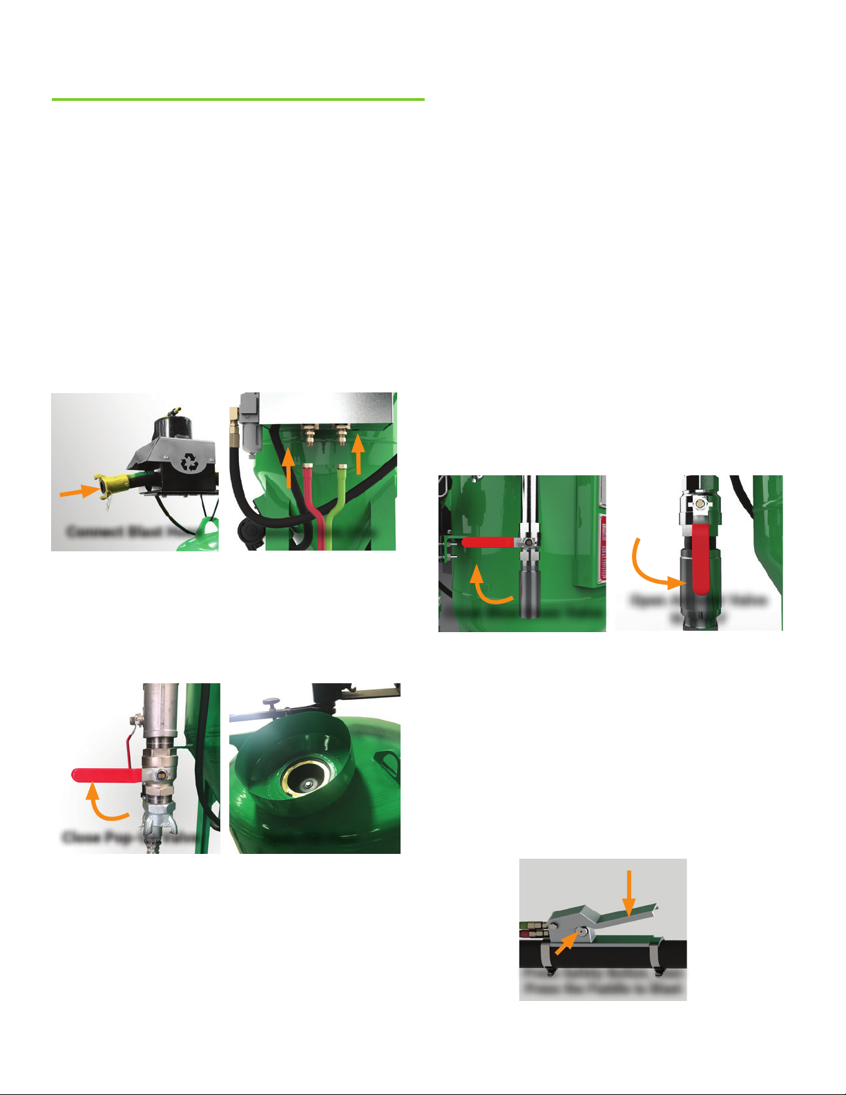
STEP 1. Connecting blast hose and twin line
Connect the blast hose to the pinch hose at the top of the
blast pot and insert the safety pin. Connect compressor
air hose to the air inlet and insert safety pin. The twin line
for your deadman controller must also be connected to the
control box on the back of the machine; red to red, green to
green.
STEP 3. Power up your compressor
Please refer to your compressor manufacturer’s manual
for operating instructions.
Before you start blasting, you will need to pressurize the
machine. Make sure the abrasive lever is unlocked, then
close the blow down valve, and open the air inlet valve.
When the machine pressurizes, you will see the abrasive
lever on the blast pot pop up.
Note: Open air inlet valve slowly to avoid sending
large amounts of compressed air into the machine
too quickly. This will cause unnecessary wear on the
system.
Note: A valve is in the open position when it is aligned
with the xture that it controls.
Note: The air inlet valve and blow down valve will always
be in opposite positions of each other.
Connect Blast Hose
Connect Twin Line
STEP 2. Filling the blast pot with abrasive
The DB800® is designed to hold:
• 75 gallons of clean water
• 750 lbs of abrasive (~50/70 mesh size)
• 100 oz of Rust Inhibitor
Close Pop-Up Valve
To open the ll port, close the pop-up valve. Then, pour in the
amount of abrasive that you need. If you are planning to use
Rust Inhibitor, add it to the blast pot now. Once complete,
remove the funnel and replace the ll cap. Everything will mix
together during the blasting process.
Open pop-up valve to close ll port.
Note: Your machine will use any type of abrasive or cleaning
medium that sinks in water and is not water soluble.
Open Fill Port
Close Blow Down Valve
SLOWLY
STEP 4. Start Blasting
• Make any necessary adjustments to abrasive lever by
rotating the rocking arm adjusting screw.
• Adjust the operating pressure with the valve behind the
lower gauge.
• Wear appropriate PPE gear.
• To activate blast hose, push the safety button in with
your thumb and slowly start pressing the handle of the
deadman controller.
Press Safety Button, then
Press the Paddle to Blast
Note: For best results, try different blast patterns and
angles to nd the best work ow.
Open Air Inlet Valve
9
Page 15
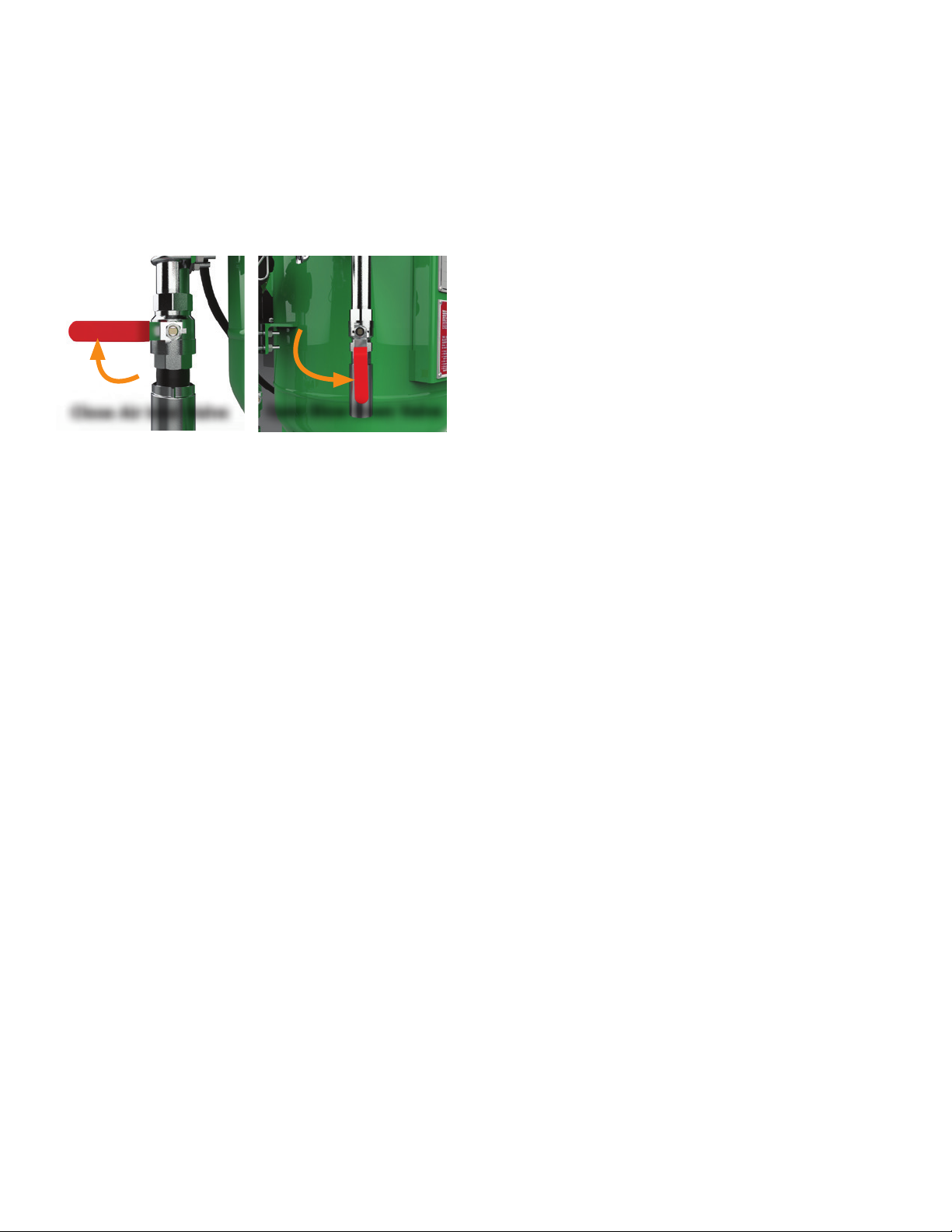
STEP 5. Shutting Down
While the compressor is running, close the air inlet valve
and open the blow down valve to release the pressure.
Let the blast pot fully depressurize before turning off the
compressor.
Close Air Inlet Valve
Note: If you turn the compressor off rst, the pressure in the
pot will backow air, water, and media into other parts of the
system, causing them to fail.
Open Blow Down Valve
10
Page 16
Maintaining your Blast Pot
CONTROL BOX MAINTENANCE
The control box has its own pressure regulator. This is already set properly from the factory, and should not be tampered
with. If it gets changed, make sure to readjust it to 90 PSI.
CONTROL BOX VALVE (LOCATED NEAR IN CONTROL BOX)
It is time to service your control box valve when the shutoff time is longer than usual or the valve is not actuating properly.
To service the control box valve (located in the control box), follow these steps:
1. Depressurize the machine.
2. Label each endcap left or right.
3. Remove the 2 (two) screws and set endcaps aside.
4. Remove piston.
5. Lightly lubricate piston with supplied grease or install new piston.
6. Install or replace any damaged gaskets or O-rings.
7. Re-install both endcaps.
PRESSURE REGULATOR
You should occasionally lubricate the threads on this knob with a lubricant such as lithium grease.
FILTER REGULATOR
You will nd the lter regulator on the left side of control box. The ltered moisture and debris will collect at the bottom
where it is vented through the screw. Leave the screw cracked open so it can let the moisture out continuously.
CONSUMPTION CHART
No damage to the machine will occur by leaving water and media inside of it. However, due to the organics in the media, a
foul smell can occur when left stagnant for longer than 24 hours. For this reason, when the machine will not be in use for
an extended period of time, it is recommended that you remove water and media from machine either by blasting it out or
by removing the bottom ange, air inlet jet, and gasket, and allow it to drain.
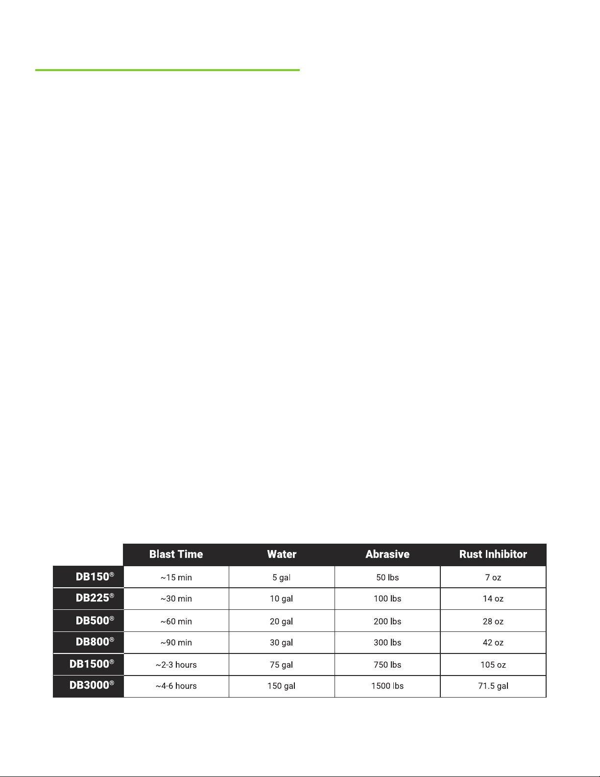
Blast pots do not need to be completely lled to operate. If maximum blast time is not needed, ll blast pot according to
required blast time.
11
Page 17
FLUSHING BLAST POT OUT
Regularly ushing the pot avoids buildup on inside walls, which could inhibit the system. Once a month or so, you should
rinse the pot out:
1. Fully depressurize machine.
2. Remove 2 bolts and 2 air inlet body lugs from bottom of machine.
3. Remove air inlet jet and gasket.
4. Push casting and air hose out of the way.
5. Flush out inside of equipment with water.
6. Once nished, replace the gasket, inlet jet, and lugs and bolts.
BLASTING WEAR PARTS
Certain parts wear faster than others and will require regular maintenance and inspection depending on the method of
blasting you are using as well as the abrasive you are blasting with. These items should be inspected for damage or wear,
and replaced an average of 400 hours if dry-blasting, or 2000 hours if wet-blasting.
Wear items include but are not limited to:
• Hardened Elbow Insert
• Hardened Air Inlet Jet
• Hardened Pipe
• Flat Backed Pinch Hose Coupling
• Inlet Jet Gasket
• Elbow Insert Gasket
• Elbow Cap Gasket
• Nozzle
PINCH HOSE MAINTENANCE GUIDE
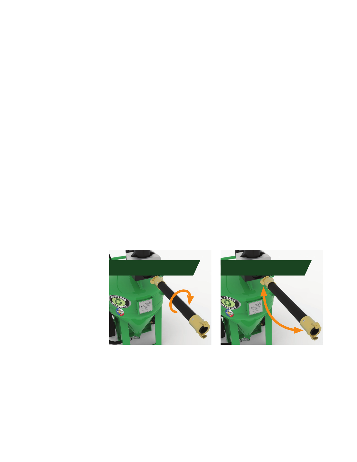
Rotate the pinch hose every 10-15 hours of blasting. Perform a visual and physical inspection to insure integrity. Look and
feel for signs of wear, softness, or bulges. Completely replace pinch hose before it fails at about 40 hours of use, or after
being rotated 4 times.
The pinch hose can be rotated
and positioned in 4 ways:
1. Starting position
2. Rotate hose 180º
3. Flip hose around
4. Rotate hose 180º again
Rotate Hose 1800 Flip Hose Around
TO REMOVE BRASS COUPLINGS FROM OLD HOSE:
1. Lock hose in vice and remove screw using a phillips head screwdriver or drill.
2. Unscrew the brass coupling from hose turning counter-clockwise. You may need a bar or rod to do this.
TO ATTACH BRASS COUPLINGS TO NEW PINCH HOSE:
1. Wrap the end of the hose in several layers of friction tape, slightly beyond the point the brass will cover.
2. Place coupling over friction tape and hose, screwing clockwise until hose end pushes against inside brass ridge of
coupling. You may need a bar or rod to get it tight.
3. Wrap screws with Teon tape and screw into designated holes until tight.
12
Page 18

Troubleshooting
MEDIA BUILD UP INSIDE POT - ADJUSTING VIBRATOR VALVE
On the left side of your control box, a small brass petcock valve controls the vibrator speed. This vibrator valve must be
open during blasting. Adjust it so that you feel maximum vibration at the head of the machine. This will insure that all of
the media gets “shaken” to the bottom of the tank.
Over time, you could experience abrasive buildup inside the pot which actually changes the harmonics of the pot. If the
system is not feeding right, adjust the valve by turning it towards the off position to slow the vibrator down, allowing the
pot to rattle more.
ABRASIVE NOT FLOWING CORRECTLY - Assuming proper Installation, air pressure, and abrasive.
Check media quality. Your machine is made to run with clean, high quality abrasive or media. Dirt will get muddy and clay
will harden.
NOTHING IS COMING OUT OF THE NOZZLE
The blast nozzle may become clogged with debris or blast media. If this occurs, put the machine in the blowdown
position, then remove the nozzle and inspect for a rock or other foreign material.
PINCH VALVE NOT OPENING OR CLOSING
1. Put the machine in the blowdown position.
2. Does the pressure gauge on the bottom left side of the control box read 80?
3. Are all ttings tightly secured to the deadman and the back of the box?
4. Is air bleeding out of the deadman?
IF YES
1. Unscrew the green hose from the control box.
2. Depress the deadman and verify air is coming out of the green hose.
If air is coming out of green hose:
1. Remove control box front panel and follow instructions for cleaning the control box valve.
2. Check that the O-Rings on the piston are not torn. If torn, order a repair kit. This part number is located on control box
back panel.
IF YES
1. Remove red hose from deadman to verify if air is coming out of it.
2. If no air is coming out, unscrew the red hose from control box and verify air coming out of it.
3. Remedy: Air line needs to be blown out to clean debris in line, and check to see if seat disk is worn.
Please call the manufacturer directly with any additional maintenance questions.
1-800-727-5707 | [email protected]
13
Page 19

Containment, Masking, and Nozzle Control
CONTAINMENT
To capture the blasting byproducts use heavy plastic or a tarp. Lay out your plastic and weigh the corners down, placing
your project in the center. You can sweep up media or use simple curtains or barriers.
MASKING
Mask off any glass, chrome, rubber seals, wiring, electrical, or moving mechanical parts and anything else that looks
delicate or like it shouldn’t have water and grit inside it. Tape works the best for protecting small parts and pieces.
NOZZLE CONTROL
It is important to use the proper nozzle to achieve the best blasting results. Nozzle size is based on air compressor size.
NOZZLE KNOWLEDGE
SLV Nozzle
• Wide blast pattern
• All purpose nozzle
ST Nozzle
• Straight bore nozzle
• Tight blast pattern
• Detailed precision nozzle
Fan Nozzle
• Spreads blast pattern out to cover a rectangular area
• Perfect for brush blasting
• Low impact compared to other nozzles
XL Performance Nozzle
• Increases abrasive particle velocity
• Allows for increased standoff distance while improving production and efciency
CLEANUP
Depending the amount of media used, plastic may be too heavy to move all at once. Cut it into sections and roll it up, or let
the water evaporate to sweep or vacuum.
Switching from Wet Blasting to Dry Blasting
BLAST WET, DRY, OR WITH SODA (AIR DRYER AND COOLER REQUIRED)
To prepare your machine for dry blasting:
1. Blast all media and water out of machine.
2. Remove ll cap.
3. Turn on air dryer and cooler.
4. Open air inlet valve halfway and let air circulate through machine for 5-7 min or until completely dry.
5. Put ll cap back on machine and pressurize tank.
6. Run air through the machine just like you were blasting for 2-3 min.
7. Shine light in machine to be sure all moisture is gone from the bottom.
8. If no moisture, ll with 1 bag of dry abrasive. Fill the remainder of the way.
Note: Using media such as plastic bead, walnut shell, corn cob, or soda requires dry blasting.
14
Page 20

Storing Machine
STORING MACHINE
If leaving unit for extended period of time, you should blast the water and media out of machine OR:
1. Fully depressurize machine.
2. Remove 2 bolts from bottom ange of machine.
3. Remove 2 lugs from bottom ange.
4. Push casting and air hose out of the way.
5. Remove air inlet jet and gasket.
7. Flush out inside of equipment with water.
Once media and water are out of machine, reverse procedure:
1. Put gasket on air inlet jet.
2. Insert air inlet jet and gasket.
3. Put casting up to bottom of machine.
4. Use lugs and bolts to secure casting.
STORING MACHINE IN WINTER
If storing your machine for the winter months, it is advised to take the following precautions to prevent damage from
freezing.
• Open all of the ball valves on your unit to prevent moisture from freezing and expanding in the valve.
Note: If wet blasting in the winter time, consider the following:
• At 32°F add rubbing alcohol to the water tank at roughly a 1:100 gallon ratio.
More alcohol can be added if necessary, up to 1:20 ratio.
• Tent around the pot, pump and moisture separator and place a heater inside to keep warm.
• Empty tank and blow out hoses.
15
Page 21

Choosing Blast Pressure
BLAST PRESSURE
Different materials and coatings call for different pressures or blasting distances. Thick metal can handle a lot of
pressure, while sheet metal could be dented by using too much pressure. Simple paint may come off nicely with the
nozzle far away, while tough undercoating may come off better with the nozzle closer.
The distance you hold the blast nozzle from the material affects the harshness and speed of the blast and changes the
"blast pattern" size. If you hold the nozzle too far away, the blast pattern will be big, but the coating will come off too
slowly. If you hold the nozzle too close, the coating will come off quickly, but the blast pattern will be small. With a tiny
blast pattern you'll have to move your arms a lot more to cover some area, which is inefcient. The best things is to nd a
nice balance between blast pattern size and removal speed.
ADJUSTING BLAST PRESSURE
The Dustless Blasting® system allows you to easily change the blast pressure by turning one simple knob. The higher the
pressure is, the higher your productivity. Obviously lower pressures are more gentle on whatever substrate you're blasting.
If you need to blast on softer material or very thin metal, lowering the pressure is a good idea to prevent damage.
A clockwise rotation of the pressure regulator knob will increase the pressure, while a counter clockwise rotation will
lower pressure. If you try to lower the pressure while the blast tank is pressurized, you'll need to either have someone blast
simultaneously, or just open the blowdown valve slightly to release some of that pressure.
COMMON GUIDELINES
Marine
On thick steel like ship hulls, you can operate at about 150 PSI. Fiberglass requires a lower pressure — about 70 PSI —
with a larger standoff distance.
Automotive
For most automotive uses, 120 PSI is ideal. Find a balance between blast pattern size, and speed.
For thick aluminum like a large trailer, you can blast at up to 150 PSI.
Grafti Removal
For removing grafti from a brick wall, use about 100 PSI so you don't etch the brick. The grafti will still come off quickly
at this low pressure.
Here is a chart of some suggested blast pressures:
Blast Pressure
Blast Distance
Fiberglass
Boats
70 PSI
18-24 in.
Brick
100 PSI
18-24 in.
Metal
(Auto)
100-120 PSI
12-14 in.
Aluminum
120-150 PSI
12-20 in.
Steel
150 PSI
10-14 in.
Blast Pattern
*The closer the nozzle is to the blast surface, the smaller the blast pattern.
Large
Large
16
Medium
Medium-Large
Medium
Page 22

Choosing Abrasive
WHAT IS ABRASIVE?
Abrasive (also called media) is mixed with water inside the blast tank. When blasting, you propel this mixture towards a
surface at high speed, to remove paint, rust, and other coatings.
TYPES OF ABRASIVE
Dustless Blasting® allows you to use a wide variety of abrasives, either wet or dry. For wet blasting, any abrasive that sinks
in water and is not water soluble can be used. However, abrasives that are dirty or have a very inconsistent particle size
can cause problems, such as sputtering or clogging of the machine.
Our favorite abrasive is recycled bottle glass, because it's clean, inexpensive, environmentally friendly, and suited for a
wide variety of jobs. Sometimes different abrasives are available simply based on geography.
A common question we get is "Can I use play sand?" The answer is NO. Play sand is not an industrial product, so it's not
controlled and graded the way abrasives are. It won't behave predictably in your equipment, and you could wind up in
loads of legal trouble, from the EPA to local municipalities. Most bags of play sand are explicitly marked "Not to be used
for sandblasting".
ABRASIVE SHAPE
Basically, there are two different shapes: angular which has sharp edges, and round with no edges.
Angular abrasive has sharp edges which will cut into the substrate, leaving an anchor prole for the new nish to stick to.
Examples of angular shaped media would be crushed glass, slags and garnet abrasives to name a few.
Round media is used mainly for cleaning or stripping while leaving the surface smooth. It will not rough up the surface or
leave an anchor prole. Examples of round media would be glass beads, sugar sand and plastic pellets.
An anchor prole is a fancy way of describing the rough surface
created during the blasting process. These peaks and valleys are
usually measured in mils (1/1000 of an inch). One of the main causes
of premature coating failure is an insufcient anchor prole. Its a good
idea to understand from the customer what he/she expects when you
are done. Some people prefer an anchor prole, while others will want a
smoother surface.
For example, if you are stripping a car to be repainted, you'll probably want to leave an anchor prole for the new paint
to adhere to. If you are simply cleaning calcium deposits from a pool — which will not be repainted — leaving a prole is
unnecessary.
ABRASIVE SIZE
Most abrasive is measured with mesh size. During production, it gets
shaken through various screens. These screens might have as little as 20
holes per square inch, or as many as 100. This means that 40/70 glass ts
through the 40–70 holes per square inch screens. 20/40 glass is coarser
than 40/70, and 60/100 glass is ner.
ANGULAR ROUND
Looks Like
20/40
40/70
60/100
17
Page 23

A common misconception is that the coarser glass will help you get through a job faster. It is true that 20/40 glass is
slightly more aggressive than 40/70. However, because it's so coarse, you're only getting half as many particles of glass in
the same size bag. You'll end up using twice as many bags to get the job done, which is not only expensive, but inefcient!
It's a much better idea to increase abrasive density if you want to complete the job faster.
ABRASIVE DENSITY
Understanding the weight or bulk density of the media you are using will also help decide which is best for the process.
The heavier the media, the more impact it has on the surface you are blasting. Imagine a golf ball and a ping pong ball.
They are the same shape and size, but the golf ball is more dense. If you threw them at someone, the golf ball would hurt
a lot more.
Crushed glass has a bulk density of 75-80 lbs per cubic foot— while garnet weighs around 145 lbs per cubic foot. So, the
two abrasives at the same mesh size and blast pressure will have different results. A 40/70 crushed glass will be more
“gentle” on the surface than the same mesh size of garnet at the same blast pressure.
The harder and heavier the abrasive is, the rougher the prole will be. Using larger, more coarse abrasives will decrease
the run time in your machine. For example, if you are blasting with 40/70 crushed glass and decide to use a larger mesh
size of 20/40 you will notice a decrease in run time. If both bags of abrasive are 50 lbs, there are fewer particles in the
20/40 mesh size bag than the 40/70. A larger mesh size will be more aggressive so it will have more of an impact to the
surface you are blasting.
ABRASIVE HARDNESS
Generally, the harder the particle, the deeper the prole it will impart. Softer abrasives, like organic materials and plastics,
are good for removing dirt, oil, grease and paint without removing any of the substrate or creating a prole.
ADJUSTING ABRASIVE SUPPLY
You will need to adjust media ow from time to time, when you are using different types of media or when you are
switching between wet and dry blasting.
When wet blasting, start with outlet pipe 1/2 inch above locked position, and adjust in 1/16 inch increments until media
runs out before water. Coarser media will require a higher outlet pipe setting.
When dry blasting, start with outlet pipe 3/8 inch above locked position and adjust in 1/16 inch increments until you reach
the desired productivity to use ratio. Setting will be closer to 1/8 inch for ne media and up to 3/4 inch for coarse media.
18
Page 24

COMPARISON CHART
Understanding the impact of different abrasives will help in deciding the best media for the job. The following chart will
explain the characteristics of various media types.
Aluminum Oxide
Crushed Glass
Glass Beads
Silicon Carbide
Plastic Abrasives
Steel Shot
Description
Sharp, long lasting
media for fast etching
& profiling
Silica-Free, 100%
recycled glass;
efficient; economical
stripping
Round, soda-lime
glass produces bright,
satin finish; minimizes
stress on part
Very hard, aggressive
cutting media; ideal
for stone, glass, and
hard surfaces
Soft media designed
for automotive &
aerospace applications
Carbon Steel, round
spheres designed for
polishing and peening
Speed
Surface
Profile
Surface
Removal
Fast High Etch Yes 8 - 9
Fast
Medium-High
Etch
Slight 5 - 6
Medium
Fast
Very Fast
Medium
No Etch
Satin Finish
Very High
Etch
No Etch
Stripping
Slight 5 - 6
Yes 9 - 9.5
Slight 3 - 4
Medium No Etch No
Hardness Bulk Density
3
3
3
3
3
3
40 - 51
HRC
110 lbs/ft
100 lbs/ft
95 lbs/ft
90 lbs/ft
50 lbs/ft
230 lbs/ft
Steel Grit
Corn Cob
Walnut Shells
Blast Sand
Sugar Sand
Garnet
Soda Bicarbonate
Coal Slag
Angular, carbon steel
for fast stripping &
aggressive cleaning
Organic, soft media
ideal for soft surfaces
such as wood
Angular, organic grit
for mildly aggressive
stripping without
damage to surface
Angular, sharp edges
that cut into substrate
and leave an anchor
profile
Round media used for
cleaning and stripping
surface
Angular hard abrasive
commonly used in
place of silica sand
Medium-sized
abrasive used to blast
smooth and strip
suraced
Angular by-product of
coal; used for removal
of coatings from steel
and concrete
Medium
Fast
High Etch Moderate
Slow No Etch No 4 - 4.5
Medium
Slow
Low Etch Very Slight 4.5 - 5
Medium
Fast
High Etch Yes 7
Medium
Fast
Very Fast
High Etch Yes 6 - 7
Very High
Etch
Yes 7.5 - 8.5
Slow No Etch No 2.5
Medium
Fast
High Etch Yes 6 - 7
19
40 - 65
HRC
260 lbs/ft
40 lbs/ft
50 lbs/ft
100 lbs/ft
100 lbs/ft
85 lbs/ft
61 lbs/ft
85 lbs/ft
3
3
3
3
3
3
3
3
Page 25

RESOURCES
TRAINING | SAFETY | REPLACEMENT PARTS
For assistance with servicing your machine, visit:
service.DustlessBlasting.com
For replacement parts and accessories, visit:
store.DustlessBlasting.com
For training resources, visit:
support.DustlessBlasting.com
To submit a ticket or to find safety data sheets, business guides,
authorization certificates, and warranty information, visit
www.DustlessBlasting.com/support
20
Page 26

Toll Free: 1-800-727-5707
International: 1-713-869-2227
www.DustlessBlasting.com
 Loading...