


T h e N e t h e r l a n d s
w w w . d t e . e u
Dutch Thermal Engineering n.v.
Westerbroekstraat 18
7011 EX Gaanderen
Phone : +31(0)315-328311
E-mail : info@dte.eu
Specialist in:
Industrial ….Cooling
….Heating
….Tempering
….Heat Recovery
V00-08-2017 Page 1
(Translation of the original instructions)
INDEX
1 DISCLAIMER ...................................................................................................................................................................................... 2
2 EU-DECLARATION OF CONFORMITY .................................................................................................................................................. 3
3 SAFETY INSTRUCTIONS AND WARNINGS ........................................................................................................................................... 4
3.1 Water draining, packing, transport and storage instructions of DTE installations. ....................................................................... 5
3.1.1 Draining water from the machine ............................................................................................................................................. 5
3.1.2 Packing, transport and storage instructions ............................................................................................................................. 7
3.2 Correct applications ....................................................................................................................................................................... 7
3.3 Application area ............................................................................................................................................................................ 7
4 GENERAL DESCRIPTION ..................................................................................................................................................................... 8
4.1 Identification.................................................................................................................................................................................. 9
5 COMMISSIONING ............................................................................................................................................................................ 10
5.1 Connecting cooling water pipes ................................................................................................................................................... 11
5.2 Connecting overflow pipe ............................................................................................................................................................ 12
5.3 Connecting power supply ............................................................................................................................................................. 12
5.3.1 Plug-in terminals ..................................................................................................................................................................... 13
5.4 Connecting external contacts ...................................................................................................................................................... 13
5.5 Water quality ............................................................................................................................................................................... 14
5.6 Filling of (external) pipes and systems CoolMaster (K) ................................................................................................................ 15
5.7 Filling of (external) pipes and systems CoolMaster (N) ................................................................................................................ 16
5.8 Filling of the system CoolMaster (K) ............................................................................................................................................ 19
5.9 Filling of the system CoolMaster (N) ............................................................................................................................................ 20
5.10 Deaerating ................................................................................................................................................................................... 21
5.11 Setting thermostat ....................................................................................................................................................................... 22
5.12 Commissioning after long standstill ............................................................................................................................................ 23
6 MEANING OF ALARMS (IF APPLICABLE) ........................................................................................................................................... 24
7 FAULT ANALYSIS .............................................................................................................................................................................. 25
8 MINIMUM INSPECTION-INTERVAL SCHEME ..................................................................................................................................... 26
9 CLEANING OF THE MACHINE............................................................................................................................................................ 27
10 CHECKS ....................................................................................................................................................................................... 27
11 SERVICE ....................................................................................................................................................................................... 27
12 GUARANTEE ................................................................................................................................................................................ 28
13 REMOVAL .................................................................................................................................................................................... 28
14 APPENDIX ................................................................................................................................................................................... 29
14.1 Options ........................................................................................................................................................................................ 30
14.2 Connection diagram filling the system ........................................................................................................................................ 31
14.3 Watertreatment .......................................................................................................................................................................... 32
14.4 Guidline for water quality in DTE installations............................................................................................................................. 33
14.5 User manual thermostat.............................................................................................................................................................. 34
14.6 Safety information sheets ............................................................................................................................................................ 37
14.7 Comments .................................................................................................................................................................................... 45
14.8 Technical information .................................................................................................................................................................. 46
* Specification list ..................................................................................................................................................................................... 46
* Machine drawing ................................................................................................................................................................................... 46
* Parts list ................................................................................................................................................................................................. 46
* Flow scheme .......................................................................................................................................................................................... 46
* Electrical scheme.................................................................................................................................................................................... 46
* User manual thermostat ........................................................................................................................................................................ 46
* Safety data sheet refrigerant ................................................................................................................................................................. 46
* Other ...................................................................................................................................................................................................... 46
ENGLISH

T h e N e t h e r l a n d s
w w w . d t e . e u
Dutch Thermal Engineering n.v.
Westerbroekstraat 18
7011 EX Gaanderen
Phone : +31(0)315-328311
E-mail : info@dte.eu
Specialist in:
Industrial ….Cooling
….Heating
….Tempering
….Heat Recovery
V00-08-2017 Page 2
11 DDiissccllaaiimmeerr
The manufacturer reserves the right to change parts at any time to change, without prior or immediate notice to the customer. The contents of
this manual may also be changed without prior warning. This is an original manual, and is valid for the machine in its standard version. The
manufacturer can therefore not be held liable for any damages resulting from specifications that deviate from the standard version delivered to
you. For information on adjustments, maintenance and repair insofar as this guide does not provide it, please contact the technical department
of your supplier. This manual was drawn up with the greatest possible care, however the manufacturer cannot accept any liability for any errors
in this book or any consequences thereof. Finally, this manual is a personal and confidential communication to the user. No part of this
publication may be reproduced, copied, altered or transmitted in any form or in any manner whatsoever without written permission from Dutch
Thermal Engineering n.v.

T h e N e t h e r l a n d s
w w w . d t e . e u
Dutch Thermal Engineering n.v.
Westerbroekstraat 18
7011 EX Gaanderen
Phone : +31(0)315-328311
E-mail : info@dte.eu
Specialist in:
Industrial ….Cooling
….Heating
….Tempering
….Heat Recovery
V00-08-2017 Page 3
22 EEUU--DDeeccllaarraattiioonn ooff ccoonnffoorrmmiittyy
Manufacturer: D.T.E. n.v.
Address: Westerbroekstraat 18
7011 EX GAANDEREN / HOLLAND
Hereby certifies that:
The CoolMaster meets the requirements of the Machinery Directive
(Directive 2006/42/EC, as amended),
and the national legislation implementing this Directive;
Meets the provisions of the following other EU directives.
- 2014/35/EU Low Voltage Directive
- 2014/30/EU EMC directive
- 2014/68/EU Pressure Equipment Directive (PED)
And furthermore certifies that
The following (parts of) harmonised standards are applied:
- NEN-EN-IEC 60204-1:2006/C11:2010
- NEN-EN-ISO 12100:2010
- NEN-EN 378-2:2016
- NEN-EN-ISO 13857:2008
The following (parts of) national technical standards and specifications are used:
- Cooling Systems Leak Tightness Arrangement (Dutch abbreviation: RLK).
Person authorised to draw up technical documentation:
Mr T.J.H.M Ratering
(Manager Engineering)
Signed in Gaanderen on 09-12-2016
F.G.R. Geerdink
General Manager

T h e N e t h e r l a n d s
w w w . d t e . e u
Dutch Thermal Engineering n.v.
Westerbroekstraat 18
7011 EX Gaanderen
Phone : +31(0)315-328311
E-mail : info@dte.eu
Specialist in:
Industrial ….Cooling
….Heating
….Tempering
….Heat Recovery
V00-08-2017 Page 4
33 SSaaffeettyy iinnssttrruuccttiioonnss aanndd wwaarrnniinnggss
Always observe the following safety instructions and warnings!
WARNING!
Warning of possible damage to the device, environment or user
WARNING!
Warning of electricity and / or current threat
WARNING!
Warning of possible entrapment hazard
Compliance with the technical manual is a prerequisite for fault-free operation and the honouring of any
warranty claims. Therefore please read the technical manual carefully before you start working with your
device! The manual must therefore be kept near the machine. The CoolMaster is under pressure with a
refrigerant, more information about this can be found in Appendix 14.6.
This user’s manual was written for types similar to DTE CoolMaster (K), (N) type machines. Therefore
certain topics may not apply to your machine. For the same reason, the images may differ slightly from
how your machine actually looks. When deviating from the standard, a machine drawing is included as
an attachment.

T h e N e t h e r l a n d s
w w w . d t e . e u
Dutch Thermal Engineering n.v.
Westerbroekstraat 18
7011 EX Gaanderen
Phone : +31(0)315-328311
E-mail : info@dte.eu
Specialist in:
Industrial ….Cooling
….Heating
….Tempering
….Heat Recovery
V00-08-2017 Page 5
33..11 WWaatteerr ddrraaiinniinngg,, ppaacckkiinngg,, ttrraannssppoorrtt aanndd ssttoorraaggee iinnssttrruuccttiioonnss ooff DDTTEE iinnssttaallllaattiioonnss..
These actions are general and have to been carried out, of course, if applicable for the
application by qualified personal!
33..11..11 DDrraaiinniinngg wwaatteerr ffrroomm tthhee mmaacchhiinnee
Step 1: Close the filling connection (D1)
Step 2: Drain the Water tank of the cooling system by opening the ball
valve. (See Figure 3.1) Further draining of the Water tank with a wet
vacuum cleaner. (See Figure 3.2)
Step 3: Drain the Tempering/Hot water tank by opening the
drainage/overflow valve. (See Figure 3.3)
Step 4: If present, switch on all solenoid valve by external power.
Step 5: If present, switch al 3 way-mix- regulation valve into the middle
position. (See Figure 3.4)
Figure 3.1
Figure 3.2
Figure 3.3
Figure 3.4

T h e N e t h e r l a n d s
w w w . d t e . e u
Dutch Thermal Engineering n.v.
Westerbroekstraat 18
7011 EX Gaanderen
Phone : +31(0)315-328311
E-mail : info@dte.eu
Specialist in:
Industrial ….Cooling
….Heating
….Tempering
….Heat Recovery
V00-08-2017 Page 6
Step 6: Drain all connection on the machine with a wet vacuum
cleaner. (See Figure 3.5)
Step 7: Open all BVS valves if present (See flow diagram) and
remove the interior (See Figure 3.6). Drain the connection on the
outside of the machine with a wet vacuum cleaner. The interior will be
transported separately and has to be assembled before
commissioning.
Step 8: Remove all plugs of the water pumps. After this drain al pumps
with a wet vacuum cleaner. (See Figure 3.7 and Figure 3.8)
Figure 3.5
Figure 3.6
Figure 3.7
Figure 3.8

T h e N e t h e r l a n d s
w w w . d t e . e u
Dutch Thermal Engineering n.v.
Westerbroekstraat 18
7011 EX Gaanderen
Phone : +31(0)315-328311
E-mail : info@dte.eu
Specialist in:
Industrial ….Cooling
….Heating
….Tempering
….Heat Recovery
V00-08-2017 Page 7
33..11..22 PPaacckkiinngg,, ttrraannssppoorrtt aanndd ssttoorraaggee iinnssttrruuccttiioonnss
Before packing, transport and storage, first follow the instructions of chapter 3.1.1 Draining water
from the machine.
Attention! Before transport the machine has to be protected with the also delivered cardboard
box or has to be wrapped with bubble wrap. The machine has to be transported and stored
perpendicular at all time on its fundament on the provided pallet!
The machine has to be placed perpendicular on its fundament at all time.
Attention! In no way the machine can be stacked or overturned. This during transport and storing
as well during repairs and commissioning. Even when the machine is not used it should be
perpendicular at all times.
Attention! Not following these instruction can cause big damage to the machine.
Use at all time the right equipment such as a pallet truck and a forklift truck.
33..22 CCoorrrreecctt aapppplliiccaattiioonnss
The CoolMaster (K)(N) may only be kept inside a cool, well-ventilated, frost-free building!
The minimum and maximum ambient temperature can be found in the relevant specifications list.
The CoolMaster (K) is only suitable for tap water of drinking quality.
The CoolMaster (N) is only suitable for tap water of drinking quality, mixing with appropriate antifreeze
(glycol) in suitable mixing ratio.
Information on the correct water-glycol ratio and the recommended type of glycol can be found on the
specification list corresponding to the machine.
Please consult the relevant specification list for information on the minimum and maximum
environmental temperature, the right water-glycol ratio and the recommended type of glycol.
Attention! In no way the machine can be stacked or overturned. This during transport and storing
as well during repairs and commissioning. Even when the machine is not used it should be
perpendicular at all times.
Attention! Not following these instruction can cause big damage to the machine.
33..33 AApppplliiccaattiioonn aarreeaa
CAUTION! Application is prohibited:
- In explosive atmospheres.
- In environments with hazardous oils, acids, gases, fumes, substances, radiation, etc.
- Corrosive environment.

T h e N e t h e r l a n d s
w w w . d t e . e u
Dutch Thermal Engineering n.v.
Westerbroekstraat 18
7011 EX Gaanderen
Phone : +31(0)315-328311
E-mail : info@dte.eu
Specialist in:
Industrial ….Cooling
….Heating
….Tempering
….Heat Recovery
V00-08-2017 Page 8
44 GGeenneerraall ddeessccrriippttiioonn
The CoolMaster is a complete plug and play water cooler with integrated water cooler tank, pump, condenser and
controls. Is built for perfect cooling in closed industrial process water systems.
A
=
Cooling water inlet, see specification list
B
=
Cooling water outlet, see specification list
C
=
Drain water tank, see specification list
D1
=
Filling water connection, see specification list
(not present in machines, specified as (N)(NF))
D2
=
Filling water facility
E
=
Overflow water tank, see specification list
F = Bushing coupling electrical supply cable
G = Control panel
H = Incoming condenser air
I = Removable cover
CAUTION! POSITION THE COVER(I) BEFORE SWITCHING ON THE
MACHINE!
J = Fixing bolts cover, 10 pieces
K = Air grille outgoing condenser air
L = Rubber legs, 4 pieces
P = Sight glass
Maximum glycol/water level
Minimum glycol/water level
S1 =
Main switch
* When deviating from the standard, a machine drawing is included as an attachment!
OFF
OFF
0
0
ON
1
S1
I
J
G
P
D2
C
F
FF
D1
A
B
E
I
H
L
K

T h e N e t h e r l a n d s
w w w . d t e . e u
Dutch Thermal Engineering n.v.
Westerbroekstraat 18
7011 EX Gaanderen
Phone : +31(0)315-328311
E-mail : info@dte.eu
Specialist in:
Industrial ….Cooling
….Heating
….Tempering
….Heat Recovery
V00-08-2017 Page 9
44..11 IIddeennttiiffiiccaattiioonn
The identification plate is located on the left next to the fan. (Figure 4.1)
A
=
Machine number/ serial number
Figure 4.1
B
=
Machine type
C
=
Voltage
D
=
Maximum Current
E
=
Number of phases
F
=
Frequency in Hz.
G
=
Refrigerant type
H
=
Refrigerant mass
I
=
Maximum ambient temperature
J
=
CO2 equivalent
K
=
GWP-values
L
=
Thermostat Temperature range
M
=
Maximum pressure
N
=
Compressor lubrication
O
=
Compressor oil volume
P
=
Built
Q
=
Weight
R
=
Cooling capacity

T h e N e t h e r l a n d s
w w w . d t e . e u
Dutch Thermal Engineering n.v.
Westerbroekstraat 18
7011 EX Gaanderen
Phone : +31(0)315-328311
E-mail : info@dte.eu
Specialist in:
Industrial ….Cooling
….Heating
….Tempering
….Heat Recovery
V00-08-2017 Page 10
55 CCoommmmiissssiioonniinngg
See for the connections chapter 4.
CAUTION! The installation work must be carried out by a certified professional!
Place the CoolMaster at a level position and at least 1 meter from a wall. For a good functioning of the
CoolMaster we recommend keeping the distance between the CoolMaster and the user to a minimum.
The cooling water pipes between the CoolMaster and the user must be longer than 15 meters.
WARNING! The diameter of the pipes/hoses must at least match with the connections on the
CoolMaster.
The hoses MUST be reinforced with braided fibre to prevent kinking the hose.

T h e N e t h e r l a n d s
w w w . d t e . e u
Dutch Thermal Engineering n.v.
Westerbroekstraat 18
7011 EX Gaanderen
Phone : +31(0)315-328311
E-mail : info@dte.eu
Specialist in:
Industrial ….Cooling
….Heating
….Tempering
….Heat Recovery
V00-08-2017 Page 11
55..11 CCoonnnneeccttiinngg ccoooolliinngg wwaatteerr ppiippees
s
1
1
Let op! Before making any connections to the CoolMaster,
clean the external pipes. Dirt must be prevented from
entering the CoolMaster. It may cause serious damage to
the system and the CoolMaster.
Connect the following pipes:
- A and B: cooling water pipes between CoolMaster and the
User.
- D1: If you wish to fill automatically.
(does not apply to machinery specified as (N))
Step 1:
1. Install the ball valve (BVS-1) on the cooling water inlet (A)
2. Install cooling water pipe between CoolMaster (BVS-1) and
User. (See Figure 5.1)
The ball valve (BVS-1) must be kept closed, unless otherwise
indicated!
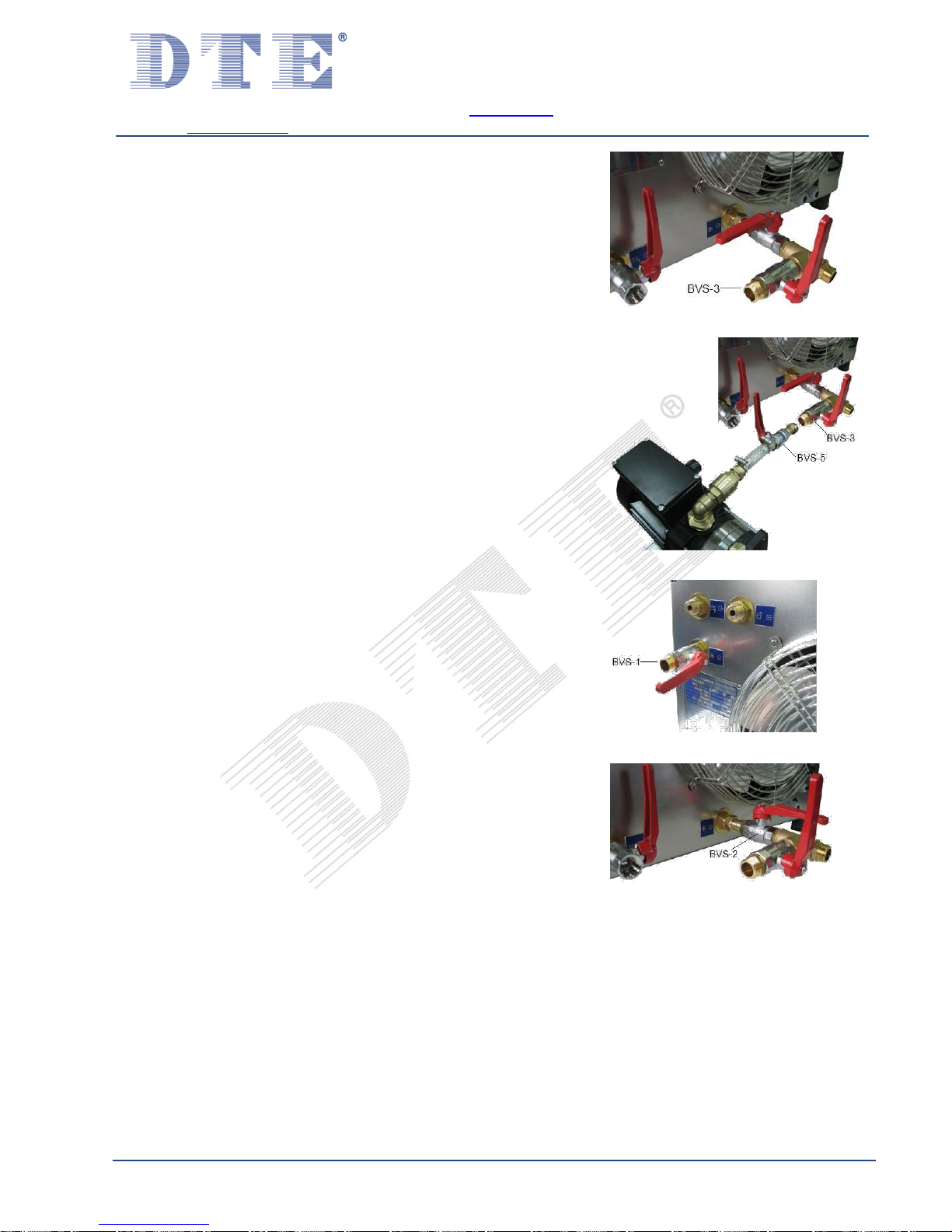
Step 2:
1. Install the ball valve (BVS-2) on the cooling water outlet (B).
2. Install the ball valve (BVS-3) on the T-piece (central section).
3. Install the cooling water pipe between CoolMaster
(on the T-piece) and the user. (See Figure 5.2)
The ball valves (BVS-2 and BVS-3) must be kept closed, unless
otherwise indicated!
Step 3:
1. Connect the cooling water pipes between CoolMaster and
user. (BVS-1 and BVS-3), See appendix §14.2
2. Connect D1 to a water tap if you wish to fill
automatically.
(does not apply to machinery specified as (N))
Figure 5.1
Figure 5.2
1
Ball valves are not supplied as standard.
Available by DTE with art. no. 87000090

T h e N e t h e r l a n d s
w w w . d t e . e u
Dutch Thermal Engineering n.v.
Westerbroekstraat 18
7011 EX Gaanderen
Phone : +31(0)315-328311
E-mail : info@dte.eu
Specialist in:
Industrial ….Cooling
….Heating
….Tempering
….Heat Recovery
V00-08-2017 Page 12
55..22 CCoonnnneeccttiinngg oovveerrffllooww ppiippee
Connect the overflow pipe (E). To enable good outflow of superfluous water, the overflow pipe must be
able to flow out into the open sewer without any foreseeable obstructions. The length of the overflow
pipe should be kept to a minimum. The pipe should also flow downwards, from the perspective of the
CoolMaster (E).
CAUTION! For machines filled with a mixture of water and glycol (machines displaying (N)), the
excess mixture from connection (E) must not be discharged into public sewers for reasons
relating to environmental law.
55..33 CCoonnnneeccttiinngg ppoowweerr ssuuppppllyy
Attention! Work may only be carried out on the electrical installation of the CoolMaster by an
authorised, professionally competent person.
Attention! The CoolMaster must only be connected to a clockwise rotary field.
Turn off the main switch on the control panel (G).
Connect your electrical power supply cable to the appropriate terminals in the control box via the cable
entry (F). Refer to the electro-technical diagram for the connection of the cable cores. Consult the
diagram number as stated on the technical specifications sheet corresponding to the serial number of
the CoolMaster.
Consult the type plate for the correct voltage.
Attention! Ensure the voltage as stated on the type plate is also the voltage on each phase wire.
Of no less importance is the mains frequency (50 or 60 Hz) corresponding to the frequency on the type
plate. The maximum voltage deviation is +6% and –10% from the voltage indicated on the type plate.

T h e N e t h e r l a n d s
w w w . d t e . e u
Dutch Thermal Engineering n.v.
Westerbroekstraat 18
7011 EX Gaanderen
Phone : +31(0)315-328311
E-mail : info@dte.eu
Specialist in:
Industrial ….Cooling
….Heating
….Tempering
….Heat Recovery
V00-08-2017 Page 13
55..33..11 PPlluugg--iinn tteerrmmiinnaallss
Use a screwdriver with a 3mm wide point. Push the screwdriver
in the square recess to open the spring. (See Figure 5.3)
Figure 5.3
Place the 10mm stripped wire with cable end into the round
recess and press the wire into the terminal as deeply as
possible. (See Figure 5.4)
Figure 5.4
Remove the screwdriver. Check whether the wire is firmly
connected. (See Figure 5.5)
Figure 5.5
55..44 CCoonnnneeccttiinngg eexxtteerrnnaall ccoonnttaaccttss
Also connect the electrical cables for the external contact(s).
See for supplied wiring diagram.

T h e N e t h e r l a n d s
w w w . d t e . e u
Dutch Thermal Engineering n.v.
Westerbroekstraat 18
7011 EX Gaanderen
Phone : +31(0)315-328311
E-mail : info@dte.eu
Specialist in:
Industrial ….Cooling
….Heating
….Tempering
….Heat Recovery
V00-08-2017 Page 14
55..55 WWaatteerr qquuaalliittyy
CAUTION! The CoolMaster is not suitable for use with demineralized water or water containing
high levels of minerals or iron.
The filling water which is used must be of good quality. It must at least be of drinking water quality and
the water must not contain high levels of lime and/or iron, as it may cause serious damage.
You must check the water regularly.
The minimum filling pressure must be 2,5 bar.
See Appendix 14.3 for extra information.
See Appendix 14.4 for directive water quality.
CAUTION! The CoolMaster (N) are only suitable for tap water of drinking water quality mixed with
the correct ratio of a suitable anti-freeze (glycol).

T h e N e t h e r l a n d s
w w w . d t e . e u
Dutch Thermal Engineering n.v.
Westerbroekstraat 18
7011 EX Gaanderen
Phone : +31(0)315-328311
E-mail : info@dte.eu
Specialist in:
Industrial ….Cooling
….Heating
….Tempering
….Heat Recovery
V00-08-2017 Page 15
55..66 FFiilllliinngg ooff ((eexxtteerrnnaall)) ppiippeess aanndd ssyysstteemmss CCoooollMMaasstteerr ((KK))
Step 1:
1. All the connections must be made in accordance with §5.1
2. Turn the air vent(s) in your system to “open”. (The venting
must take place at the highest point(s) in pipe(s))
CAUTION! Do not use automatic air vents!
CAUTION! CoolMaster (N) filling procedure in §5.9
3. Connecting the filling water (min. 2.5 Bar) to BVS-3.
4. Turn the valve (BVS-3) to “open”. (See Figure 5.6)
Step 2:
Excess air will be released from the pipe(s) though the air
release valve(s).
If the water spills from the air release valve(s), the external
pipes/systems are filled with water.
1. Turn the ball valve (BVS-3) to “closed”. (See Figure 5.7)
2. Turn the air release valve(s) in your system to the
"closed" position.
3. Turn the water fill line to “closed”.
4. Remove the fill water line which is mounted on BVS-3.
Step 3:
1. Turn the ball valve (BVS-1) to “open”. (See Figure 5.8)
2. Turn the ball valve (BVS-2) to “open”. (See Figure 5.9)
When these steps have been completed correctly, the entire
system will be filled with water.
Figure 5.6
Figure 5.7
Figure 5.8
Figure 5.9

T h e N e t h e r l a n d s
w w w . d t e . e u
Dutch Thermal Engineering n.v.
Westerbroekstraat 18
7011 EX Gaanderen
Phone : +31(0)315-328311
E-mail : info@dte.eu
Specialist in:
Industrial ….Cooling
….Heating
….Tempering
….Heat Recovery
V00-08-2017 Page 16
55..77 FFiilllliinngg ooff ((eexxtteerrnnaall)) ppiippeess aanndd ssyysstteemmss CCoooollMMaasstteerr ((NN))
Step 1:
1. The connections must be made in accordance with §5.1.
The ball valve (BVS-1) must be kept closed, unless otherwise
indicated! (See Figure 5.10)
CoolMaster (N)
Filling set for mixture of water and glycol 2
Step 2:
See Figure 5.11 and Figure 5.12. for a complete image from
the filling set. The mixture of water and glycol will be provided
in the supplied tank.
The ratio of the mixture is indicated in the relevant specification
list.
Figure 5.10
Figure 5.11
Figure 5.12
Figure 5.13
2
The fillingset is not supplied as standard.
Available by DTE with art. no. 87000089

T h e N e t h e r l a n d s
w w w . d t e . e u
Dutch Thermal Engineering n.v.
Westerbroekstraat 18
7011 EX Gaanderen
Phone : +31(0)315-328311
E-mail : info@dte.eu
Specialist in:
Industrial ….Cooling
….Heating
….Tempering
….Heat Recovery
V00-08-2017 Page 17
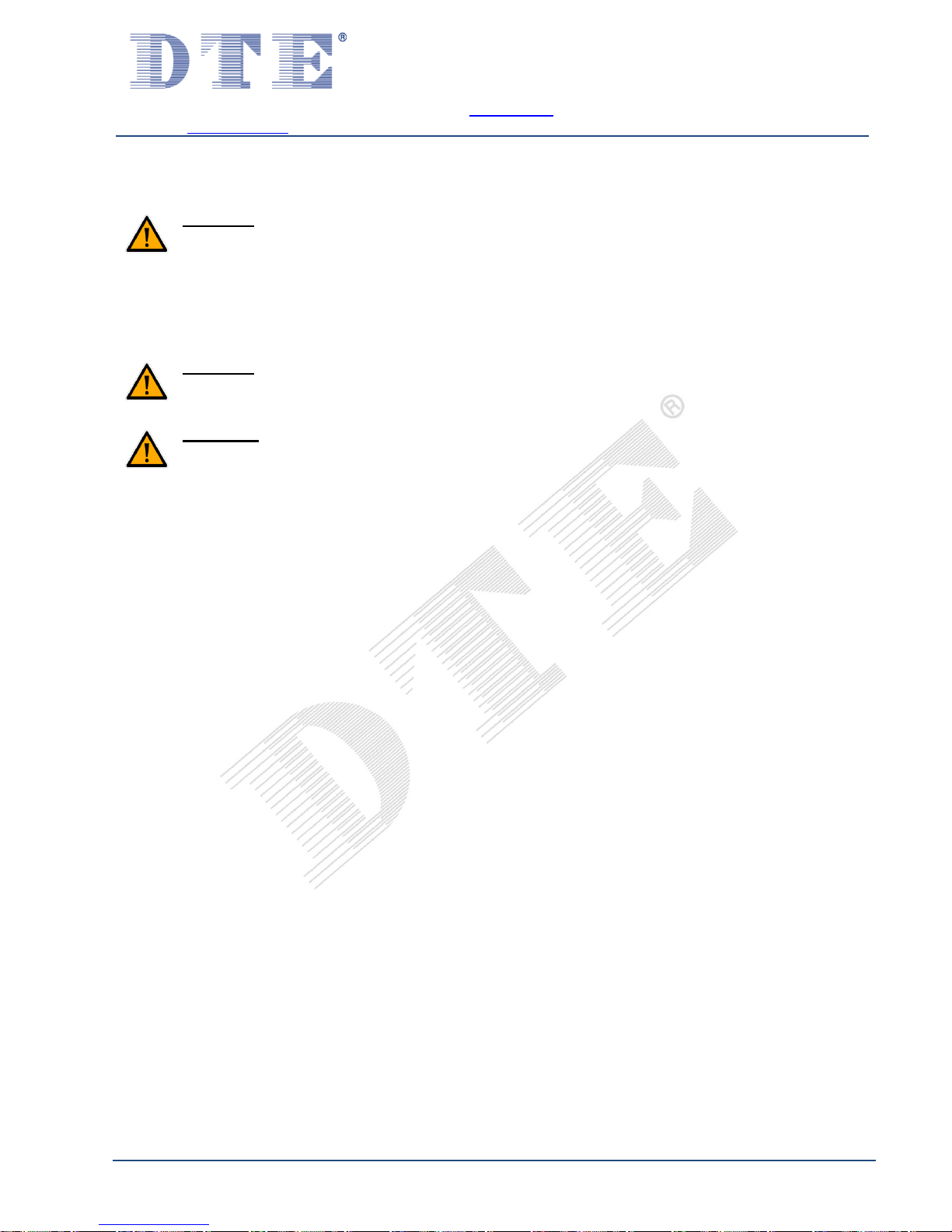
1. Install the cooling water pipe between CoolMaster
(on the T-piece) and the user.
The ball valve (BVS-2 and BVS-3) must be kept closed, unless
otherwise indicated! (See Figure 5.13)
2. Install the link (BVS-5) onto the ball valve (BVS-3) (Minimum
pressure 2.5 bar). (See Figure 5.14)
Step 3:
1. Turn the air release valve(s) to “open”. (It is essential
that the air release(s) takes place at the highest
point(s) in the pipe(s))
CAUTION! Do not use automatic air release valves!
2. Turn the ball valve (BVS-5) to “open”.
(See Figure 5.15)
3. Turn the ball valve (BVS-3) to “open”.
(See Figure 5.16 and Figure 5.17)
Figure 5.14
Figure 5.15
Figure 5.16
Figure 5.17
T h e N e t h e r l a n d s
w w w . d t e . e u
Dutch Thermal Engineering n.v.
Westerbroekstraat 18
7011 EX Gaanderen
Phone : +31(0)315-328311
E-mail : info@dte.eu
Specialist in:
Industrial ….Cooling
….Heating
….Tempering
….Heat Recovery
V00-08-2017 Page 18
Step 4:
Excess air will be released from the pipe(s) though the air
release valve(s).
If the water and glycol mixture spills from the air release
valve(s), the external pipes/systems are filled with the water
and glycol mix.
1. Turn the ball valve (BVS-3) to “closed” (See Figure 5.18)
2. Turn the air release valve(s) in your system to the
"closed" position.
3. Turn the ball valve (BVS-5) to “closed”:
4. Remove the ball valve (BVS-5) (See Figure 5.19)
Step 5:
1. Turn the ball valve (BVS-1) to “open” (See Figure 5.20)
2. Turn the ball valve (BVS-2) to “open” (See Figure 5.21)
When these steps have been completed correctly, the entire
system will be filled with the water and glycol mixture.
Figure 5.18
Figure 5.19
Figure 5.20
Figure 5.21

T h e N e t h e r l a n d s
w w w . d t e . e u
Dutch Thermal Engineering n.v.
Westerbroekstraat 18
7011 EX Gaanderen
Phone : +31(0)315-328311
E-mail : info@dte.eu
Specialist in:
Industrial ….Cooling
….Heating
….Tempering
….Heat Recovery
V00-08-2017 Page 19
55..88 FFiilllliinngg ooff tthhee ssyysstteemm CCoooollMMaasstteerr ((KK))
Fill the CoolMaster with water (fill automatically or manually):
1. Auto fill (D1) (a power supply is required; a minimum filling
pressure of 2.5 bar is required). (See Figure 5.22)
2. Manual fill (D2). (See Figure 5.23)
External systems must be filled via an external filling point.
See chapter §5.6 for instructions.
WARNING! To add any chemicals or other substances,
please consult the supplier.
Figure 5.22
Figure 5.23

T h e N e t h e r l a n d s
w w w . d t e . e u
Dutch Thermal Engineering n.v.
Westerbroekstraat 18
7011 EX Gaanderen
Phone : +31(0)315-328311
E-mail : info@dte.eu
Specialist in:
Industrial ….Cooling
….Heating
….Tempering
….Heat Recovery
V00-08-2017 Page 20
55..99 FFiilllliinngg ooff tthhee ssyysstteemm CCoooollMMaasstteerr ((NN))
CoolMaster (N): Fill the CoolMaster with the mix of water and
glycol (using manual fill D2). (See Figure 5.24)
WARNING! This mixture must be prepared beforehand.
Filling with water first and adding the glycol afterwards or
vice versa is prohibited. For the mixing ratio for this
machine see the appropriate specifications list.
External systems must be filled via an external filling point. See
chapter §5.7 for instructions.
To add any chemicals or other substances, please consult the
supplier.
WARNING! To prevent the heat exchange and/or other
parts from freezing, the mixing ratio of the water and
glycol mix must be checked weekly by taking a sample
from the tank. If the mixing ratio is not correct, this may
affect the warranty.
Figure 5.24

T h e N e t h e r l a n d s
w w w . d t e . e u
Dutch Thermal Engineering n.v.
Westerbroekstraat 18
7011 EX Gaanderen
Phone : +31(0)315-328311
E-mail : info@dte.eu
Specialist in:
Industrial ….Cooling
….Heating
….Tempering
….Heat Recovery
V00-08-2017 Page 21
55..1100 DDeeaaeerraattiinngg
WARNING! DO NOT START THE PUMP BEFORE IT IS
FILLED WITH LIQUID AND DEAERATED!
This machine is fitted with a bypass and will therefore
automatically be deaerated.
Figure 5.25
Figure 5.26
WARNING! Ensure the compressor is disabled when
starting up for the first time!
Step 1: Remove the removable cover from the machine (I).
(See Figure 5.25 and Figure 5.26)
Step 2: Turn on the installation and let the pump run for 10
minutes to get the system deaerated.
Step 3: The whole system is now deaerated, the cover can be
placed into place. The compressor is reactivated now
the removable cover is back into place.
T h e N e t h e r l a n d s
w w w . d t e . e u
Dutch Thermal Engineering n.v.
Westerbroekstraat 18
7011 EX Gaanderen
Phone : +31(0)315-328311
E-mail : info@dte.eu
Specialist in:
Industrial ….Cooling
….Heating
….Tempering
….Heat Recovery
V00-08-2017 Page 22
55..1111 SSeettttiinngg tthheerrmmoossttaatt
See chapter §4 for the specified parts.
CAUTION! COVER(I) MUST BE PLACED, BEFORE STARTING
UP THE MACHINE!
Switch on the main switch (S1) on the control panel (G).
Switch on the external start/stop.
Set the thermostat to the correct value, which is on the front of the control panel (G).
Zie appendix 14.5 for the settings.
CAUTION! It is important that the values in the specifications list are adhered to, otherwise
damage to the compressor may occur! When temperatures set incorrectly the guarantee claim
may expire!
WARNING! This machine is equipped with a bypass, which is erected between water supply and
water return pipe inside the CoolMaster. The minimum flow is already factory defined and may
not be hanged!
The CoolMaster is now ready for use.
T h e N e t h e r l a n d s
w w w . d t e . e u
Dutch Thermal Engineering n.v.
Westerbroekstraat 18
7011 EX Gaanderen
Phone : +31(0)315-328311
E-mail : info@dte.eu
Specialist in:
Industrial ….Cooling
….Heating
….Tempering
….Heat Recovery
V00-08-2017 Page 23
55..1122 CCoommmmiissssiioonniinngg aafftteerr lloonngg ssttaannddssttiillll
CAUTION! BEFORE OPENING MACHINE, ALWAYS
ENSURE POWER SUPPLY IS COMPLETELY
DISCONNECTED!
Figure 5.27
Figure 5.28
DTE uses reputable components in its products, whereby DTE
will reduce the risk of faults in its machines.
This also applies to the water pumps. These pumps are made
with a stainless steel fan, a high quality pump house and a
“Mechanical seal” to seal the axis. The mechanical seal is a
high quality axis seal made from polished hard metal, and all
contact surfaces are polished. This will guarantee a good
sealing even under the toughest operating circumstances. The
mechanical seal will lubricate itself by means of a thin liquid
layer of the pumped fluid.
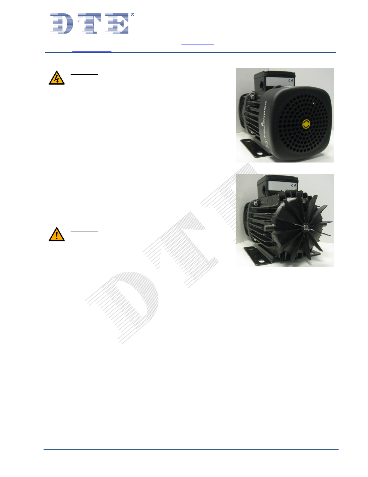
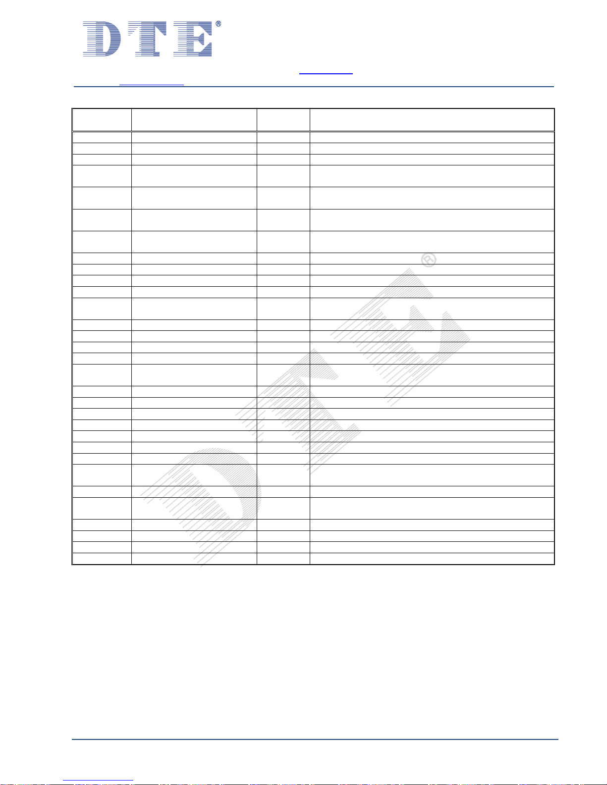
When the machine has not been used for a long period there is
a chance that the water pump will not run. The cause of this
fault may be cohesion between the polished contact surfaces
of the mechanical seals. The seals "stick together". This
problem is easily solved by rotating the pump axis by hand. In
the Grundfos pump, it can be done by first removing the roster
by unscrewing the two screws. You can now rotate the engine
fan by hand. The sticking together has now been broken and
the machine can be started. (See Figure 5.27 and Figure 5.28)
CAUTION! MAKE SURE TO REPLACE THE ROSTER,
OTHERWISE THE PUMP ENGINE WILL NOT BE COOLED
PROPERLY!

T h e N e t h e r l a n d s
w w w . d t e . e u
Dutch Thermal Engineering n.v.
Westerbroekstraat 18
7011 EX Gaanderen
Phone : +31(0)315-328311
E-mail : info@dte.eu
Specialist in:
Industrial ….Cooling
….Heating
….Tempering
….Heat Recovery
V00-08-2017 Page 24
66 MMeeaanniinngg ooff aallaarrmmss ((iiff aapppplliiccaabbllee))
Fault
Possible cause
Check and solution
1. Level Alarm
1.1. Water level is too low
1.1. Check the water level
on the gauge glass, refill
if necessary
1.2. Check whether the machine
refills automatically
(if connected)
1.3. Check water inlet
1.4. Check valves
1.5. Check for leaks
2. Compressor
Alarm
2.1. Thermal alarm or short-circuit
compressor(s)
2.1. Check for short-circuit
2.2. Check for overload of
compressor(s)
3. Condenser
Alarm
3.1. Thermal alarm or short-circuit
fan(s)
3.1. Check for short-circuit
3.2. Check for overload of
fan(s)
4. Water pump
Alarm
4.1. Thermal alarm or short-circuit
water pump(s)
4.1. Check for short-circuit
4.2. Check for overload of
pump(s)
5. Filling
5.1. Filling system
5.1. Check liquid level
5.2. Refill manually if necessary
5.3. In the event of malfunctions please
contact the supplier

T h e N e t h e r l a n d s
w w w . d t e . e u
Dutch Thermal Engineering n.v.
Westerbroekstraat 18
7011 EX Gaanderen
Phone : +31(0)315-328311
E-mail : info@dte.eu
Specialist in:
Industrial ….Cooling
….Heating
….Tempering
….Heat Recovery
V00-08-2017 Page 25
77 FFaauulltt aannaallyyssiiss
Have all checks and repairs performed by a certified technician!
Fault
Possible cause
Check and solution
1. Unit does not start
1.1. Faulty wiring
1.2. Components down to earth
1.3. Faulty main switch
1.4. Controls incorrectly set
1.5. Removable cover not
correctly placed on machine
1.1. Check wiring and connections
1.2. Check and replace
1.3. Check and replace
1.4. Check, see electric diagram
1.5. Place removable cover
2. Fan(s) run but
compressor will not
start
2.1. Faulty wiring
2.2. Faulty relay, or security
2.3. Faulty compressor
2.1. Check wiring and connections
2.2. Check components
2.3. Check and replace
3. Compressor starts but
no air is delivered over
the condenser
3.1. Fan loose on shaft
3.2. Faulty fan motor
3.3. Faulty wiring
3.4. Blocked air flow
3.1. Tighten fixing screw
3.2. Check and replace
3.3. Check wiring and connections
3.4. Clean the condenser
4. Compressor switches
off
4.1. Electricity supply
4.2. Faulty thermostat
4.3. Faulty relay, or security
4.4. Internal security activated
4.1. Check electricity supply
4.2. Check and replace
4.3. Check and replace
4.4. Water and/or ambient temperature
too high. Check cleanliness of
condenser and clean it
5. Unit does not cool
5.1. Shortage of freon
5.2. Faulty compressor
5.3. Faulty thermostat
5.4. Faulty pump
5.1. Refill
5.2. Check and replace
5.3. Check and replace
5.3. Check and replace
6. Water pump gives
no water
6.1. Water pump not de-aerated
6.2. Impeller of water pump is stuck
6.3. Faulty relay, or security
6.1. De-aerate water pump
6.2. See: chapter 5.12
6.3. Check components
7. Shortage of freon
7.1. Leak in the system
7.1. Check the system for leakage and
repair

T h e N e t h e r l a n d s
w w w . d t e . e u
Dutch Thermal Engineering n.v.
Westerbroekstraat 18
7011 EX Gaanderen
Phone : +31(0)315-328311
E-mail : info@dte.eu
Specialist in:
Industrial ….Cooling
….Heating
….Tempering
….Heat Recovery
V00-08-2017 Page 26
88 MMiinniimmuumm IInnssppeeccttiioonn--iinntteerrvvaall sscchheemmee
Inspection interval
Inspection points
Weekly
monthly
Every
6 months
Every
12 months
Every
24 months
Mechanical
Visual check on damage outside of
the unit
X
Visual check fans on damage
X
Visual check fan on prevalence
X
Visual (and auditive) check on
defects
X
Visual check of wiring/cabling
X
Cleaning condenser by using with
compressed air or vacuum cleaner
X
Cleaning fan blade(s) to prevent
imbalance
X
Check the hermetical system leaks
X
Pressure temperatures and
refrigeration installation check
X
Cleaning the compressor with damp
cloth.
X
Retracing hose clamps
X
Check mixing ratio water/glycol (only
for CoolMaster (N))
X
Check water quality
X
Electrical
Check all potential indicators and
earthings
X
Power consumption check
X
Check wiring main switch for damage
X
Visual check electrical components
and contactors
X
Torque for hose clamps
Hose ø 13mm.
10 N/m
Hose ø 19mm.
12 N/m

T h e N e t h e r l a n d s
w w w . d t e . e u
Dutch Thermal Engineering n.v.
Westerbroekstraat 18
7011 EX Gaanderen
Phone : +31(0)315-328311
E-mail : info@dte.eu
Specialist in:
Industrial ….Cooling
….Heating
….Tempering
….Heat Recovery
V00-08-2017 Page 27
99 CClleeaanniinngg ooff tthhee mmaacchhiinnee
CAUTION! ONLY APPLIES TO THE EXTERIOR CASING!
Before cleaning the machine, make sure you completely disconnect the power supply.
To clean the machine use a soft brush, with lukewarm water with a non-aggressive cleaner. Then
rub the machine dry with a soft, dry cloth. Unless explicitly stated otherwise the machine must
not be cleaned with a high-pressure cleaner and/or other powerful water jets!
1100 CChheecckkss
We recommend carrying out the following checks every week:
- Check the fan motor(s) and fan blade(s) for pollution and operation.
- Ensure the water pump(s) has no leaks.
- Check the water and glycol mixture. (if applicable)
We recommend carrying out the following checks every month:
- Clean condenser plates with compressed air and/or vacuum cleaner.
- (Caution: The condenser plates can be sharp!)
- Check all wiring and connections.
- Ensure the hermetical system has no leaks.
- Check water level of the water tank at the gauge glass (P).
- Check the flow of the by-pass.
1111 SSeerrvviiccee
If a problem and/or advise is needed from our technical staff, please always mention:
- Serial number
- Ambient temperature
- What is shown at the display of the thermostat
- What is the setpoint of the thermostat
- Which alarm signals are given
By mention these points, a quick solution of the problem can be given.
Dutch Thermal Engineering n.v.
Westerbroekstraat 18
7011 EX Gaanderen
Tel.: +31(0)315-328311
E-mail: service@dte.eu

T h e N e t h e r l a n d s
w w w . d t e . e u
Dutch Thermal Engineering n.v.
Westerbroekstraat 18
7011 EX Gaanderen
Phone : +31(0)315-328311
E-mail : info@dte.eu
Specialist in:
Industrial ….Cooling
….Heating
….Tempering
….Heat Recovery
V00-08-2017 Page 28
1122 GGuuaarraanntteeee
One or more components in this CoolMaster are sealed.
Breaking these seals or adjusting components which are not sealed, may void your guarantee.
Always contact your supplier. When claiming one or more components under the guarantee, these
components must be returned to the supplier uncleaned and in their original state.
Otherwise, the guarantee conditions on this machine apply as described in the general conditions of
delivery and payment. These were deposited at the Chamber of Commerce in Arnhem on 05-06-1989, a
copy of which is available upon request.
1133 RReemmoovvaall
The CoolMaster consists primarily of stainless steel, copper, brass and aluminium. The CoolMaster is
also compressed with a refrigerant which is specified in the “specification list” and the relevant safety
data sheet.
Removal of the CoolMaster must be carried out in accordance with local or national legislation. Contact
your government for instructions.

T h e N e t h e r l a n d s
w w w . d t e . e u
Dutch Thermal Engineering n.v.
Westerbroekstraat 18
7011 EX Gaanderen
Phone : +31(0)315-328311
E-mail : info@dte.eu
Specialist in:
Industrial ….Cooling
….Heating
….Tempering
….Heat Recovery
V00-08-2017 Page 29
1
1
4
4
A
A
p
p
p
p
e
e
n
n
d
dii
x
x

T h e N e t h e r l a n d s
w w w . d t e . e u
Dutch Thermal Engineering n.v.
Westerbroekstraat 18
7011 EX Gaanderen
Phone : +31(0)315-328311
E-mail : info@dte.eu
Specialist in:
Industrial ….Cooling
….Heating
….Tempering
….Heat Recovery
V00-08-2017 Page 30
1144..11 OOppttiioonnss
Options Part list
Part
Article no.
K2 Connectingset (SP)
87000087
K2 Control box sealing + Heating
87000065
K2 Control box sealing
87000064
K2 Connectingset
87000055
K2 Manifold with control valve for connection of 3 machines
87000011
K2 Manifold with control valve for connection of 2 machines
87000010
K2 Black blow function for emptying the forms
87000009
Tag numbers
87000006
K2 wire numbers
87000005
K2 Wheels (1 pair fixed, 1 pair castoring) stainless steel
87000004
K2 Manometer (installed in the supply line external to
machine)
87000002
K2 Check valve 3 wc, mounted external to machine
87000001
Filling Unit, water/glycol
87000089
Filling Set for external system
87000090
Table 1: Order list options

T h e N e t h e r l a n d s
w w w . d t e . e u
Dutch Thermal Engineering n.v.
Westerbroekstraat 18
7011 EX Gaanderen
Phone : +31(0)315-328311
E-mail : info@dte.eu
Specialist in:
Industrial ….Cooling
….Heating
….Tempering
….Heat Recovery
V00-08-2017 Page 31
1144..22 CCoonnnneeccttiioonn ddiiaaggrraamm ffiilllliinngg tthhee ssyysstteemm
Figure 14.1

T h e N e t h e r l a n d s
w w w . d t e . e u
Dutch Thermal Engineering n.v.
Westerbroekstraat 18
7011 EX Gaanderen
Phone : +31(0)315-328311
E-mail : info@dte.eu
Specialist in:
Industrial ….Cooling
….Heating
….Tempering
….Heat Recovery
V00-08-2017 Page 32
1144..33 WWaatteerrttrreeaattmmeenntt
INTRODUCTION
Semi-closed and closed cooling systems are used in many processes.
An efficient and effective cooling system is needed for a process to function without problems.
Generally such cooling systems contain between 0.5 and 5.0 m³ water,
which is normally topped up with tap water. The tap water available is often, technically speaking, of poor quality:
contains limescale and/or
is corrosive
The system may contain many different materials with which the cooling water comes into contact. Such as:
steel/cast iron
copper/brass
aluminium
synthetics/sealants
PROBLEM DEFINITION
Corrosion problems can occur in cooling systems, which have different causes.
The presence of different materials can result in galvanic corrosion, which is where the least precious metal is
dissolved. The action of oxygen on iron and steel causes oxygen corrosion and the formation of iron oxide or silt.
Natural silt accumulation can lead to “under deposit corrosion”. High flow-speeds can lead to erosion corrosion.
The quality of the cooling water plays a significant role in this.
GENERAL MEASURES
Contamination
Measure
Mechanical contamination caused by iron oxides or silt
Install filters, depending on contamination
High hardness
Soften water via ion exchange
Minor contamination caused by presence of oxides
and hardness
Use water treatment in the form of hardness stabilisation
and corrosion inhibitors
Biological contamination caused by presence of algae
and slime bacteria
Use water treatment in the form of biocides
WATER TREATMENT
Specific water treatment should be used if one or more values cannot be maintained or achieved.
Water treatment products can be used for a wide variety of applications in this case. DTE has a water treatment in the form of
PollutionMaster. This product can optionally be supplied. If the temperature of the water exceeds approx. 40°C, (partial) water
softening must in general be applied.
A complete water treatment proposal can be drawn up after the water quality has been assessed on site.
CLEANING
If the cooling system is already very contaminated, we recommend cleaning the system with a suitable cleaning product. The
cleaning solution can be pumped around using the system pump or an cleaning pump.
For the best cleaning result, at least some flow should be established across all components. The cleaning progress can be
monitored through visual inspection and using pH test strips.
Systems with considerable biological contamination should be rinsed thoroughly first. A bio-dispergator can also be used for this
purpose.
The cleaning method and costs will be assessed and determined per situation.
Note: You can contact DTE anytime.

T h e N e t h e r l a n d s
w w w . d t e . e u
Dutch Thermal Engineering n.v.
Westerbroekstraat 18
7011 EX Gaanderen
Phone : +31(0)315-328311
E-mail : info@dte.eu
Specialist in:
Industrial ….Cooling
….Heating
….Tempering
….Heat Recovery
V00-08-2017 Page 33
1144..44 GGuuiiddlliinnee ffoorr wwaatteerr qquuaalliittyy iinn DDTTEE iinnssttaallllaattiioonnss
Water quality for use in all DTE installations is prescribed in this general guideline. Water quality used in DTE
installations should meet this standard at all times.
Standard values for water quality:
- Acidity: PH 7 < PH 9,5
- Chloride: < 50mg / L
- Conductivity: 150 µS < 350µS
- Bicarbonate (HCO3): 80mg/L < 100mg/L
- Hardness: 2dH° < 8dH°
This directive is a general directive which also applies to systems in which water with a percentage of glycol is
used.
In cases where a water-glycol mixture is to be applied, the quality of water must first be analysed to be ensured the
water quality is within the norm values. Subsequently, a water-glycol mixture may be prepared that must be tested
on mixing ratio before use.
In the system the absorption of oxygen must prevented to keep the hydrogen carbonate (HCO3) level within the
acceptable range. In case of doubt, this should be tested with a sufficient frequency.

T h e N e t h e r l a n d s
w w w . d t e . e u
Dutch Thermal Engineering n.v.
Westerbroekstraat 18
7011 EX Gaanderen
Phone : +31(0)315-328311
E-mail : info@dte.eu
Specialist in:
Industrial ….Cooling
….Heating
….Tempering
….Heat Recovery
V00-08-2017 Page 34
1144..55 UUsseerr mmaannuuaall tthheerrmmoossttaatt
KLT12ID:
SETPOINT CHANGE
Push “SET” once (set point will be displayed flashing).
Change the set point by pressing “UP” and “DOWN”.
Confirm the changed set point with “SET”.
Parameter programming
(These parameters are factory set. Do not change them!)
1. To enter the parameters push the ‘’SET’’-button for at least 8 seconds. Value ‘’00’’ will appear, flashing.
2. Enter the correct code by pressing “UP” and “DOWN”. (this is factory-set to ‘’00’’)
3. Press ‘’SET’’ to confirm the code. If this is correct, the label of the first parameter will appear.
4. Using the “UP” and “DOWN” button, select the desired parameter.
5. Press ‘’SET’’ to see the value.
6. Change the parameter by pushing “UP” and “DOWN”.
7. Confirm with "SET".
8. To change more parameters, repeat step 4, 5 and 6.
9. The controller will return to its normal condition after 60 sec, or just press the ‘’SET’’ + ‘’DOWN’’ button.
Parameter list
Parameter
Description
Factoryvalue
Comment
‘’SET’’
Set point
15
Change possible between US and LS
r0
Set point differential
2
Differential on/off controller, this parameter may not be
changed!!
r1
Minimum set point
5
Sets the minimum acceptable value for the set point
r2
Maximum set point
20
Sets the maximum acceptable value for the set point
r3
Normal or differential
adjustment
Nor
r4
Diff. For diff. mode
0.1
r5
Diff. setpoint
0.0 r6
Fan operation
con d0
Cold or Hot control
re
Re=Cold, in=Hot
d1
End of defrost. temp
80 d2
Max. defrost time
0 d3
Defrost when connecting
No d4
Delay first defrost
0.0
h-m
d5
Display on defrosting
Off d6
Display return limit
15 d7
Compressor drip time
0 d8
Interval between defrost
0 d9
Fan works with defrost
No d10
Fan drip time
0 d11
Manual defrost sync.
No
d12
Defrost probe
SD1 d14
Units to count defrost cycle
Rt
T h e N e t h e r l a n d s
w w w . d t e . e u
Dutch Thermal Engineering n.v.
Westerbroekstraat 18
7011 EX Gaanderen
Phone : +31(0)315-328311
E-mail : info@dte.eu
Specialist in:
Industrial ….Cooling
….Heating
….Tempering
….Heat Recovery
V00-08-2017 Page 35
Parameter list
Parameter
Description
Factoryvalue
Comment
A0
Set point
2.0
Degrees
A1
Max. Alarm temperature
85
Alarm high value
A2
Min. alarm temperature
5.0
Alarm low value
A3
Alarm exclusion time during
continuous cycle
0.0
Minutes
A4
Alarm exclusion time
After defrost
0.0
Minutes
A5
Alarm exclusion time after
opening door
0.0
Minutes
A6
Alarm exclusion after
connection
0.0
Minutes
A7
Alarm verification time
0.0
Minutes
A8
Ext. alarm verification time
0.0
Minutes
F0
Fan stoppage temperature
0.0 F1
Fan works with door open
Yes
c0
Min. stoppage time
compressor
1
Minimum interval between the compressor start and stop
(value in minutes)
c1
Continuous cycle time
0.0
Minutes
c2
ON-time of fault cycle
0
Minutes
c3
OFF-time of fault cycle
999
Minutes
c4
Min. ON-time
0
Minutes
c5
Min. time between 2
ignitions of compressor
0
Minutes
P0
Temperature scale
°C
°C or °F
P1
Ambient probe calibration
-1.0
Allows to adjust possible offset of the thermostat probe
P2
Defrosting probe calibration
0
Allows to adjust possible offset of the thermostat probe
P4
Decimal point
Yes
Display point on/off
P5
Probe to be displayed
SD1 P6
Number of probes used
1 E0
Digital input
off
Digital input not used
H0
Selection to record a
configuration
0
H1
Keypad protection
No
H2
Service cut due to digital
input
No
H3
Delay time on connecting
0
Minutes
H4
Address for serial comms
0 H5
Keyboard code
0 H6
Type of probe
NTC
T h e N e t h e r l a n d s
w w w . d t e . e u
Dutch Thermal Engineering n.v.
Westerbroekstraat 18
7011 EX Gaanderen
Phone : +31(0)315-328311
E-mail : info@dte.eu
Specialist in:
Industrial ….Cooling
….Heating
….Tempering
….Heat Recovery
V00-08-2017 Page 36
DISPLAY MESSAGE:
In normal operation the probe temperature selected by P5 will be displayed. But the following messages may also
appear:
- ‘’Err’’ - Memory reading error
- ‘’Erp’’ - Probe error, not viewed in display
- ‘’Eri’’ - Internal parameter error. In this case, enter the above DTE-configuration
- ‘’ALH’’ - High temperature alarm
- ‘’ALL’’ - Low temperature alarm (temperature is 5 degrees lower then ‘’SET”)
- ‘’ALE’’ - External alarm
- ‘’AEL’’ - High and external alarm
- ‘’000’’ - Probe open
- ‘’---‘’ - Probe short-circuited
- ‘’DON’’ - Defrosting activated
- ‘’DOF’’ - Defrosting de-activated, or cannot be done
- ‘’CON’’ - Continuous cold cycle
- ‘’COF’’ - Continuous cold cycle de-activated, or cannot be done
- ‘’-d-‘’ - Thermostat on defrosting
- ‘’OFF’’ - Thermostat switched OFF, can be switched on by pressing the ‘’UP’’ and ‘’DOWN’’-button
simultaneously for at least 8 seconds
MAINTENANCE
- Cleaning
Clean the surface of the controller with a soft, damp cloth. NEVER use abrasive detergents, alcohol or
solvents
- Repairs/Programming
All repairs and the programming of the thermostat must be carried out by authorised professional.
T h e N e t h e r l a n d s
w w w . d t e . e u
Dutch Thermal Engineering n.v.
Westerbroekstraat 18
7011 EX Gaanderen
Phone : +31(0)315-328311
E-mail : info@dte.eu
Specialist in:
Industrial ….Cooling
….Heating
….Tempering
….Heat Recovery
V00-08-2017 Page 37
1144..66 SSaaffeettyy iinnffoorrmmaattiioonn sshheeeettss
The refrigerant safety data sheet is sent separately as an attachment!
MONOPROPYLENE GLYCOL USP
1. IDENTIFICATION OF THE PRODUCT AND THE COMPANY
Substance name:
MONOPROPYLENE GLYCOL USP
Substance type:
Raw material
Supplier:
BREUSTEDT CHEMIE BV
POSTBUS 721
7300 AS APELDOORN
THE NETHERLANDS
Tel.
055-5332844
Fax.
055-5429072
2. COMPOSITION OF AND INFORMATION ON THE INGREDIENTS
Official substance name:
MONOPROPYLENE GLYCOL USP
CAS no.:
Annex 1 no.:
3. DANGER IDENTIFICATION
Not a dangerous product according to guideline 67/548/EEG
4. FIRST AID MEASURES
Swallowing:
No harmful effects are expected in case of this type of exposure
Eyes:
Rinse extensively with water
Skin:
Rinse skin with plenty of water or shower
Inhaling:
No harmful effects are expected in case of this type of exposure, in association with the correct
professional usage.
5. FIRE FIGHTING MEASURES
Risks:
Stability:
Stable under normal circumstances
Preventative measures:
Extinguishing agents:
Water spray, carbon dioxide, foam and extinguishing powder
Fire:
Incomplete incineration may lead to the formation of carbon monoxide and propionaldehyde
6. MEASURES IN CASE OF UNWANTED RELEASE
Personal precautions
Swallowing
Do not eat, drink or smoke during work
Eyes
Safety glasses with side protection
Skin
Prevent skin contact, wear gloves
Inhaling
Ventilation, wear breathing protection if limit is exceeded
Environmental precautions/cleaning methods
Cleaning/waste
If possible, recover or re-use, or dispose of waste in accordance with the applicable legislation.

T h e N e t h e r l a n d s
w w w . d t e . e u
Dutch Thermal Engineering n.v.
Westerbroekstraat 18
7011 EX Gaanderen
Phone : +31(0)315-328311
E-mail : info@dte.eu
Specialist in:
Industrial ….Cooling
….Heating
….Tempering
….Heat Recovery
V00-08-2017 Page 38
7. HANDLING AND STORAGE
Storage
In a ventilated, dry space, separate from strongly oxidizing substances
8. EXPOSURE MANAGEMENT/PERSONAL PROTECTION
Swallowing
Do not eat, drink or smoke during work
Eyes
Safety glasses with side protection
Skin
Prevent skin contact, wear gloves
Inhaling
Ventilation, wear breathing protection if limit is exceeded
Exposure details
ppm
mg/m3
ceiling value
Absorption through
skin?
MAC-TGG 8 hours
50
10
No No
MAC-TGG 15 min
No
WGW values
No
WGD recommended
values
No
BGW values
No
9. PHYSICAL AND CHEMICAL CHARACTERISTICS
Description
MONOPROPYLENE GLYCOL USP
Blacklist substance?
No
Physical form
Liquid
Colour
Colourless, clear
Appearance form
Liquid
Odour
None Molecular mass
Not available
Odour threshold
Not available
ppm
Vapour pressure (mbar)
0.3 mbar
Boiling point/pathway
188
°C
Vapour pressure (bar)
Not available
bar
Melting point/pathway
Not available
°C
Density (water=1)
1.04 g/cm3
Sublimation
point/pathway
Not available
°C
Vapour density (air=1)
2.62 g/cm3
Flash point
103
°C
Water solubility
Completely
Auto-ignition temp.
371
°C
Soluble in
Not available
Dissolution temperature
Not available
°C
pH
N/a
Lower explosion
threshold
2.6
Vol%
Viscosity
Not available
Upper explosion
threshold
12.5
Vol%
As a standard temperature and standard pressure 20 °C and 1 atm. (=103,325 kPa) apply unless stated
otherwise
Other details
Anti-freeze
10. STABILITY AND REACTIVITY
Reactivity
Dangerous reactions: with caustic potash and caustic soda (T<200 C), oxidizing
substances
Stability
Stable under normal circumstances
Preventative measures

T h e N e t h e r l a n d s
w w w . d t e . e u
Dutch Thermal Engineering n.v.
Westerbroekstraat 18
7011 EX Gaanderen
Phone : +31(0)315-328311
E-mail : info@dte.eu
Specialist in:
Industrial ….Cooling
….Heating
….Tempering
….Heat Recovery
V00-08-2017 Page 39
11. TOXICOLOGICAL INFORMATION
Carcinogenic
No
Reprotoxic (for the reproduction of poisoning)
No
Sensitising
No
Special indication
Mutagenic
No
Inhaling
Coughing, headache, sore throat
Skin
Redness, pain
Eyes
Redness, pain
Swallowing
Abdominal pain, nausea
Ingestion via
Swallowing and inhaling, no hazardous effects are expected
Other toxicological details
LD50 oral, rat: > 5000 mg/kg
LD50 dermal, rabbit: > 10000 mg/kg
Skin irritation rabbit: not irritating, irritation of eyes rabbit: not irritating
Sensitisation: causes no skin conditions
12. ECOLOGICAL INFORMATION
LC50 vis, 96 h: 4600-54900 mg/l
EC50 Daphia Magna, 48h: 4850-34400 mg/l
Biological degradation, 28 days 86% (BOD 28 > 60%)
No long-term negative effects are expected in a watery environment
13. POINTS OF ATTENTION FOR REMOVAL
Cleaning/waste
If possible, recover or re-use, or dispose of waste in accordance with the applicable legislation.
BAGA
KCA/KGA
14. INFORMATION WITH REGARD TO TRANSPORT
Transport
This product has been classified as non-hazardous in accordance with international transport
regulation
UN no.
Packaging group
GEVI no.
Other transport
codings
Class
No.
Edge
no.
TEC no.
Sheet
no.
EMS
MFAG no.
NFPA-code
Road
ADR/VLG
Water
ADN
ADN(R)
IMDG
Rail
RID/VSG
Air
IATA/ICAO
15. INFORMATION WITH REGARD TO REGULATION
Chem. Identity
MONOPROPYLENE GLYCOL USP
EC no.
Contains
Safety datasheet (VIB) according NEN-ISO 11014:2009

T h e N e t h e r l a n d s
w w w . d t e . e u
Dutch Thermal Engineering n.v.
Westerbroekstraat 18
7011 EX Gaanderen
Phone : +31(0)315-328311
E-mail : info@dte.eu
Specialist in:
Industrial ….Cooling
….Heating
….Tempering
….Heat Recovery
V00-08-2017 Page 40
16. OTHER INFORMATION
Comments
Liability
This safety data sheet (SDS) was drawn up in accordance with the NEN-ISO 11014:2009 guidelines. It was
drawn up with the utmost care and the data is based on current knowledge and experience.
However, the responsibility for using this SDS rests with the employer.
But we cannot accept liability for damage of any kind arising from the use of this data or use of the product.
The safety data sheet describes products for their safety requirements. This
information is no guarantee for product properties. It is the duty of the user to use this product with care and
to comply with the applicable laws and regulations.

T h e N e t h e r l a n d s
w w w . d t e . e u
Dutch Thermal Engineering n.v.
Westerbroekstraat 18
7011 EX Gaanderen
Phone : +31(0)315-328311
E-mail : info@dte.eu
Specialist in:
Industrial ….Cooling
….Heating
….Tempering
….Heat Recovery
V00-08-2017 Page 41
MONO ETHYLENE GLYCOL
1. IDENTIFICATION OF THE PRODUCT AND OF THE COMPANY
Substance name
MONO ETHYLENE GLYCOL
Substance type
Raw material
Application
Frost protective additive for liquid extinguishing agents
Supplier
BREUSTEDT CHEMIE BV
POSTBUS 721
7300 AS APELDOORN
THE NETHERLANDS
Tel.
055-5332844
Fax.
055-5429072
2. COMPOSITION OF AND INFORMATION ON THE INGREDIENTS
Official substance name
MONO ETHYLENE GLYCOL USP
CAS no.:
Annex 1 no.
3. RISKS
The vapour mixes well with air. Reacts strongly with oxidation agents and oxidising acids. The substance can be absorbed into the
body through inhalation and swallowing. The substance is an irritant to eyes and skin. The substance has an effect on the nervous
system. Liver, kidney, and brain damage may occur. In serious cases there is a risk of unconsciousness.
Flammable substance: avoid open fire. Use in explosive safe environment, ensure there are earthing and spark-free tools.
Do not consume any food or drink when using or processing, and do not smoke.
4. FIRST AID MEASURES
Swallowing
Symptoms: Diarrhoea, stomach cramps, headache, dizziness, vomiting, sleepiness. Have
mouth rinsed, try to avoid vomiting and immediately transport to hospital
Skin and eye contact
Symptoms: Redness. Rinse or shower with plenty of water. Rinse eyes for long time (if
possible, remove contact lenses) Warn a doctor
Inhaling
Symptoms: Headache, dizziness, sleepiness. Take the victim into the fresh air and allow
him/her to rest
5. FIRE FIGHTING MEASURES
Suitable extinguishing agents
Powder, alcohol proof foam, water spray, carbon dioxide
Specific extinguishing methods
None
Specific exposure dangers
None
Protection in case of fire fighting
Wear chemical-resistant clothing and respiratory protection
6. MEASURES IN CASE OF UNWANTED RELEASE
Personal precautions
Wear chemical-resistant clothing and respiratory protection. Wear safety gloves and glasses.
Remove contaminated clothing and follow first aid measures
Environmental measures
Dam in spilt product and carefully vacuum it up, clear it up. Absorb it with absorption grains
Cleaning methods
Remove residuals with water

T h e N e t h e r l a n d s
w w w . d t e . e u
Dutch Thermal Engineering n.v.
Westerbroekstraat 18
7011 EX Gaanderen
Phone : +31(0)315-328311
E-mail : info@dte.eu
Specialist in:
Industrial ….Cooling
….Heating
….Tempering
….Heat Recovery
V00-08-2017 Page 42
7. HANDLING AND STORAGE
Handling
Use personal protection equipment
Storage
In a ventilated, dry space, separate from strongly oxidative substances
8. EXPOSURE MANAGEMENT/PERSONAL PROTECTION
Swallowing
Do not eat, drink or smoke during work
Eyes
Safety glasses with side protection
Skin
Prevent skin contact, wear gloves
Inhaling
Ventilation, wear breathing protection if limit is exceeded
Threshold value/MAC value
10 ppm / 26 mg/m3 in droplets (maximum not to be exceeded)
Protected breathing
Extraction. Filter mask A. processing or use in well-ventilated space
Protection of hands
Safety gloves
Protection of eyes
Safety glasses
Protection of skin
Protective clothing
9. PHYSICAL AND CHEMICAL CHARACTERISTICS
Description
MONO ETHYLENE GLYCOL
Blacklist substance?
No
Physical form
Liquid
Colour
Colourless, clear
Appearance form
Liquid
Odour
None
Molecular mass
Not available
Odour threshold
Not available
pp
Vapour pressure (mbar)
0,12 @ 25 °C
mbar
Boiling point/pathway
179
°C
Vapour pressure (bar)
Not available
bar
Melting point/pathway
-13
°C
Density (water=1)
1.1 g/cm3
Sublimation
point/pathway
Not available
°C
Vapour density (air=1)
2.1 @ 25 °C
g/cm3
Flash point
116
°C
Water solubility
Completely
Auto-ignition temp.
413
°C
Solubility in water
Fully soluble
Dissolution temperature
Not available
°C
pH
N/a
Lower explosion
threshold
3.2
Vol
%
Viscosity
Not available
Upper explosion
threshold
28
Vol
%
As a standard temperature and standard pressure 20 °C and 1 atm. (=103.325 kPa) unless stated otherwise
Other details
Anti-freeze
10. STABILITY AND REACTIVITY
Circumstances to be avoided
Keep separate from food
Substances to be avoided
Reacts strongly with oxidation agents and oxidising acids.
Hazardous degradation
products

T h e N e t h e r l a n d s
w w w . d t e . e u
Dutch Thermal Engineering n.v.
Westerbroekstraat 18
7011 EX Gaanderen
Phone : +31(0)315-328311
E-mail : info@dte.eu
Specialist in:
Industrial ….Cooling
….Heating
….Tempering
….Heat Recovery
V00-08-2017 Page 43
11. TOXICOLOGICAL INFORMATION
Carcinogenic
No
Reprotoxic (for the reproduction of poisoning)
No
Sensitising
No
Special indication
Mutagenic
No
Inhaling
Coughing, headache, sore throat
Skin
Redness, pain
Eyes
Redness, pain
Swallowing
Abdominal pain, nausea
Ingestion via
Swallowing and inhaling, no hazardous effects are expected
Other toxicological details
LD50 oral, rat: > 5000 mg/kg
LD50 dermal, rabbit: > 10000 mg/kg
Skin irritation rabbit: not irritating, irritation of eyes rabbit: not irritating
Sensitisation: causes no skin conditions
12. ENVIRONMENTAL INFORMATION
Exotoxicity
LC goldfish: > 5000 mg/l
Persistence/degradation
BOD: 0.47; COD: 1.24
13. POINTS OF ATTENTION FOR REMOVAL
Cleaning/waste
If possible, recover or re-use, or dispose of waste in accordance with the applicable legislation.
14. INFORMATION WITH REGARD TO TRANSPORT
Transport
UN no.
Packaging group
GEVI no.
Other transport
codings
Class
No.
Edge
no.
TEC no.
Sheet
no.
EMS
MFAG no.
NFPA-code
Road
ADR/VLG
Water
ADN
ADN(R)
IMDG
Rail
RID/VSG
Air
IATA/ICAO
15. INFORMATION WITH REGARD TO REGULATION
Chem. Identity
MONO ETHYLENE GLYCOL
EC no.
Contains

T h e N e t h e r l a n d s
w w w . d t e . e u
Dutch Thermal Engineering n.v.
Westerbroekstraat 18
7011 EX Gaanderen
Phone : +31(0)315-328311
E-mail : info@dte.eu
Specialist in:
Industrial ….Cooling
….Heating
….Tempering
….Heat Recovery
V00-08-2017 Page 44
16. OTHER INFORMATION
Comments
Liability
This safety data sheet (SDS) was drawn up with the utmost care and the data is based on current
knowledge and experience.
However, the responsibility for using this SDS rests with the employer.
But we cannot accept liability for damage of any kind arising from the use of this data or use of the
product.
The safety data sheet describes products for their safety requirements. This
information is no guarantee for product properties. It is the duty of the user to use this product with care
and to comply with the applicable laws and regulations.

T h e N e t h e r l a n d s
w w w . d t e . e u
Dutch Thermal Engineering n.v.
Westerbroekstraat 18
7011 EX Gaanderen
Phone : +31(0)315-328311
E-mail : info@dte.eu
Specialist in:
Industrial ….Cooling
….Heating
….Tempering
….Heat Recovery
V00-08-2017 Page 45
1144..77 CCoommmmeennttss

T h e N e t h e r l a n d s
w w w . d t e . e u
Dutch Thermal Engineering n.v.
Westerbroekstraat 18
7011 EX Gaanderen
Phone : +31(0)315-328311
E-mail : info@dte.eu
Specialist in:
Industrial ….Cooling
….Heating
….Tempering
….Heat Recovery
V00-08-2017 Page 46
1144..88 TTeecchhnniiccaall iinnffoorrmmaattiioonn
** SSppeecciiffiiccaattiioonn lliisstt
** MMaacchhiinnee ddrraawwiinngg
** PPaarrttss lliisstt
** FFllooww sscchheemmee
** EElleeccttrriiccaall sscchheemmee
** UUsseerr mmaannuuaall tthheerrmmoossttaatt
** SSaaffeettyy ddaattaa sshheeeett rreeffrriiggeerraanntt
** OOtthheerr
* Technical information is sent as an attachment to the technical operating instructions.
 Loading...