


Installation and Operation Manual
for
Speed Dome Camera
Please read the operation manual carefully
before installing and using this unit
VER:1.0

1
CONTENTS
Packing List -------------------------------------------------------------2
CAMERA SPECIFICATION--------------------------------------------- 3
1. PRECAUTIONS-------------------------------------------------------- 4
2. OPERATION------------------------------------------------------------ 5
3. ID SETTING------------------------------------------------------------- 8
4. PROTOCOL SETTING----------------------------------------------- 8
5. CONSTRUCTION----------------------------------------------------- 9
6. TROUBLESHOTING------------------------------------------------- 10
7. CONNECTION OF RS485 BUS AND
TERMINATION RESISTER----------------------------------------- 11
8. INSTALLATION-------------------------------------------------------- 12
APPENDIX -------------------------------------------------------- 15
● Lightning proof equipment must be installed when the speed
dome camera is installed in open area.
● Make sure the input voltage and normal rated power before
powered up.
Warnings!

2
10X PTZ Packing List
No.
Name
QTY/ Unit
Remark
1
Speed Dome Camera
1
2
DC12V power supply adapter
1 3
English Operation Manual
1
4
Bracket
1
(Standard)
5
Wall Bracket
1
(Option)
6
Cable
1 7
Accessories packing
1

3
CAMERA SPECIFICATION
ITEMS
IQ952
SYNC System
Internal Mode
/ External (AC Lock) Mode (±1Hz)
Scanning System
1:2 Interlace
Chipset
Sony HAD II
Effective Pixels
976 (H) X 582 (V) (PAL)
S/N
More than 46 dB
( γ = 1,AGC OFF,APC OFF,Y-out)
Horizontal Resolution
540 TV Lines
Lens
F1.6(W) ~1.9(T)
f=3.6(W)~122.8(T)mm
Zoom
36 x Optical Zoom and 10X Digital Zoom
White Balance
ATW/AWB/FIX (Zero Color Rolling)
ALC
Auto/Fix (OSD Control)
AGC
+24dB (Max)
BLC Function
48 Zone BLC (OSD Control)
ICR Function
YES
Minimum Illumination
1.5 Lux(F1.8/50IRE)
ICR ON 0.02 Lux
Electronic Shutter
AES: 1/60(1/50) ~1/120,000 sec. Manual: 8 Step
GAMMA Correction
0.45 / 1
Video Signal Output
1.0Vp-p / 75Ω
External Control
RS485
Pan
Speed 0.5 ~ 50°/s
Tilt
Speed 0.5 ~ 50°/s
Preset
128 Preset Positions (Max)
Auto Cruise
6 Auto Cruising Tracks (Max)
Operation Temperature
-10℃ ~50℃
Operation Humidity
Within 90% RH
Power Source
100 – 240 VAC | 10W
Weight
14000Gram

4
Sizes
295 Ø x 322 mm
1. PRECAUTIONS
(1) Do not attempt to disassemble the camera.
To prevent electric shock, do not remove screws or covers.
There are no user-serviceable parts inside.
Ask qualified service personnel for servicing.
(2) Handle the camera with care.
Do not abuse the camera. Avoid striking, shaking, etc. The camera could be damaged by improper handling
or storage.
(3) Do not use strong or abrasive detergents when cleaning the camera body.
Use a dry cloth to clean the camera when it is dirty.
When the dirt is hard to remove, use a mild detergent and wipe gently. Care should be taken not to scratch the
dome when wiping it. Afterwards, wipe off the remained part of the detergent in it with a dry cloth.
(4) Never face the camera towards the sun.
Do not aim the camera at bright objects. Whether the camera is in use or not, never aim it at the sun or other
extremely bright objects. Otherwise, blooming or smear maybe caused.
(5) Never face the camera towards a place exposed to light sources for a long time.
If light sources such as spot light cause burn-in on the display screen, part of image may discolor due to
deterioration of color filter in CCD when changing aim of the camera etc.
(6) Do not install this camera upside down.
This camera is designed for mounting on the ceiling or wall. Using this camera installed upside down, for
example, mounted on the floor, may cause malfunction.
(7) Do not operate the camera beyond the specified temperature, humidity or power source ratings.
Do not use the camera in an extreme environment where high temperature or high humidity exists. Do not
place near heat sources such as radiators, stoves or other units that produce heat.
Use the Indoor Speed Dome camera under conditions where temperature is between -30°C - +50°C, and
humidity is below 85 %. The input power source is DC12V.
(8) Do not install the camera near the air out-let of an air conditioner.
The lens may become cloudy due to condensation if the camera is used under the following conditions.
• Rapid temperature fluctuations by switching the air conditioner on and off
• Rapid temperature fluctuations due to frequent door opening and closing
• Use in an environment where eyeglasses become foggy
• Use in a room filled with cigarette smoke or dust.
If the lens becomes cloudy due to condensation, remove the dome cover and wipe all moist surfaces with a

5
soft cloth.
(9) Consumables
Parts having contacts such as the lens-drive motors, cooling fan motor and slip-rings built inside the camera are
subject to wear with time. About replacement and maintenance of such parts, please ask the nearest service
center.
(10) Do not aim the camera at the same object for a long time.
Burn-in of an image may be caused on the fluorescent screen of CRT.
2.OPERATION
The speed dome camera can be controlled remotely horizontal and vertical movement. It is controlled
remotely from the keyboard or controller through a serial connection to the RS-485 connector.
The speed dome camera will conduct a self-check after powered up and the monitor will display as following
(Only for IQ750):―P:P-D2400, ID:001, V10‖. The information will be disappeared after the self-check is
finished.(Protocol and ID code will be displayed according to the users’ choice)
Normal Function:
2.1 Pan/Tilt Function
The camera is capable of moving vertically and horizontally. The Pan/Tilt speed is variable for given amount of
joystick deflection.
2.2 Lens Function(Only for IQ750)
2.2.1 Zoom Lens Function(IQ750)
Transform the view angle of the camera(zoom in / zoom out), press[TELE] or [WIDE] .
2.2.2 Focus Function(Only for IQ750)
In some special circumstance, users need conduct focus manual, he can press [NEAR] or [FAR] to transform the
focus.
2.2.3 Iris Function(Only for IQ750)
In normal circumstance, iris is in auto mode. If users need to change the iris level, they can press [OPEN] or
[CLOSE] to adjust.
2.3 Preset Function
The speed dome camera is capable of going to 32 preset positions. Each is with its own P/T/Z and focus. When
preset a camera position, the P/T/Z and focus will be memorized for that position.
2.3.1 To set a preset position
First input"PRESET", and then input the number of preset position and press“ENTER”at the end.
[PRESET] + N + [ENTER], N→the number of preset position: 1~ 32.
2.3.2 To call a preset position
When camera positions have been preset, you can enter a memorized camera position number.
[CALL] + N + [ENTER], N→the number of preset position: 1~ 32.
2.3.3 To delete a preset position:
First input"PRESET",and then input the preset position number and press“OFF”at the end.
[PRESET] + N + [OFF], N→the number of preset position which will be deleted.
2.4 Setting of the Pan scan between two points:
1) The dome device conduct auto Pan Scan between two preset positions.
2) Users can set the starting point by pressing ―PRESET+52+ENTER‖ and set the ending point by pressing
―PRESET+53+ENTER‖.
3) press ―CALL+52+ENTER‖ to start Pan scan.

6
4) The dwell time of “starting point” and “ending point” of Pan scan is 4 seconds.
5) Stop it by operate “Pan”or “Tilt”.
6) You can cancel the point by pressing ―PRESET+52+OFF‖
2. 5 Operation instruction about the tour scan movement:
1) Auto point by point scan from preset point number 1 to number 16, if a certain point is not set or
cleared,
that point will not be scan when “tour scan” is in progress.
2) The dwell time of preset point in tour is 4 seconds.
3) The defaulted tour function can be executed by inputting ―CALL+51+ENTER‖.
4) Stop it by operate “Pan”or “Tilt”.
2. 6 Setting of Home position :
This means the time duration for the dome device to return to the number 1 direction preset position when
no-man control occurs.
1) Start this function by pressing ―CALL+54+ENTER‖.
2) The time of returning to preset direction position number 1 can be set to 1 minute / 5 minutes / 10
minutes / 30 minutes / 60 minutes by pressing ―CALL+55+ENTER‖ / ―CALL+56+ENTER‖ / ―CALL+57+ENTER‖
/ ―CALL+58+ENTER‖ / ―CALL+59+ENTER‖.
3) Disable this function by pressing “PRESET+54+ENTER‖.
2. 7 Intelligent three-dimension tour scan setting :
When the user is monitoring with manual Pan scan, he only needs to maintain the scan direction to
continue the scan monitoring, and then press “CALL+50+ENTER” to auto continue the manual Pan scan
action.
2. 8 Six groups of programmable tour:
It has the functions of tour setting and call out, as well as saving the directional used programmed
tour. Each group of tour contains 12 preset positions, the running speed and dwell time of which can be
set and the data will not be lost when the power is off.
2.9 Integrated swivel and tilt movement
1)Pan rotation is 360º endless; Tilt movement is 20~90º,by using the key boards speed can be adjustable
from 0.5~30º/s.
2) The low speed running is stable with ultra-low noise and without image shake.
3) by pushing down the Joystick till the point of 90º the camera will auto lift up 10 degree. Monitoring all
directions with ±2º precision.
3.0 OSD MENU exit (only for IQ750)
There are three ways to exit the menu after you enter the menu by pressing “CALL+64+ENTER”, the first
way is by pressing “PRESET+64+ENTER”, the second way is by using joystick to keep turning left for about 3
seconds , the third way is also by using joystick, but turn left for several times.
3.1 Special Function—Power-off Protection
When the camera is under scan or cruise track, and power off occurs, the camera will save the state
before the power-off. When power is resupplied, the camera will continue to perform the scan or cruise track
automatically under the same state before power-off. Should scan or cruise track are not performed before
power-off, the camera will stop at the first preset position automatically.

7
3.2 Auxiliary Functions List
Operation
Function IQ750
Preset + N + Enter
Set the number N preset position (1≤N≤32)
Preset + N + OFF
Clear the number N preset position (1≤N≤32)
Call + N + Enter
Call the number N preset position (1≤N≤32)
Call + 50 + Enter
Auto Intelligent Tour Pan Scan
Call + 51 + Enter
Auto cruise (preset position from No.1 to No.16)
Preset + 52 +
Enter
Set the Starting Point of the Pan Scan between two
points
Preset + 53 +
Enter
Set the End Point of the Pan Scan between two
points
Preset +52 + OFF
Clear the Points of the Pan Scan between two points
Call + 52 + Enter
Pan Scan between the two Seeting points
Call + 54 + Enter
Auto Back Home ON
Preset + 54 +
Enter
Auto Back Home OFF
Call + 55 + Enter
Auto Back Home after 1 minute when Auto Back
Home is ON
Call + 56 + Enter
Auto Back Home after 5 minute when Auto Back
Home is ON
Call + 57 + Enter
Auto Back Home after 10 minute when Auto Back
Home is ON
Call + 58 + Enter
Auto Back Home after 30 minute when Auto Back
Home is ON
Call + 59 + Enter
Auto Back Home after 60 minute when Auto Back
Home is ON
SHOT+N+ON+(TELE
or WIDE)+OFF
Set the cruise tracks N (1≤N≤6)
SHOT+N+Enter
Call the cruise tracks N (1≤N≤6)
SHOT+N+OFF
(long press)
Clear the cruise tracks N (1≤N≤6)
Operation
Function IQ750
Call + 64 + Enter
Camera Menu ON
Preset + 64 +
Enter
Camera Menu OFF
Call + 65 + Enter
Backlight Compensation ON
Preset + 65 +
Enter
Backlight Compensation OFF
Call + 66 + Enter
Digital Zoom ON
Preset + 66 +
Enter
Digital Zoom OFF
Call + 67 + Enter
Camera Preset ON

8
Call + 68 + Enter
Image Mirror ON
Preset + 68 +
Enter
Image Mirror OFF
Call + 69 + Enter
Image Up-side down ON
Preset + 69 +
Enter
Image Up-side down OFF
Call + 70 + Enter
Image Negative
Preset + 70 +
Enter
Image Positive
Call + 71 + Enter
Image Freeze ON
Preset + 71 +
Enter
Image Freeze OFF
Call + 72 + Enter
Color Bar ON
Preset + 72 +
Enter
Color Bar OFF
Call + 73 + Enter
Preset OSD ON
Preset + 73 +
Enter
Preset OSD OFF
Call + 74 + Enter
Camera Menu OSD in Chinese
Call + 75 + Enter
Camera Menu OSDin English
Call + 76 + Enter
Camera Menu OSD in Japenese
WIDE
Zoom Wide
TELE
Zoom Tele
FAR
Focus Far
NEAR
Focus Near
OPEN
IRIS Open
CLOSE
IRIS Close
3.ID SETTING
ID of this speed dome can be set by the switch with 8 codes. Below is the detail of setting ID code:
(Turn the power off when setting, and restart the device after revision).
The figure shows: Address of the dome device: No. 1
(Please refer to detailed parameter in next chapter)
Set address for dome

9
This switch “S2” (ID NUMBER setting) located on PCB in the dome device.
4.PROTOCOL SETTING
Protocol of this speed dome can be set by the switch with 3 protocol codes. Below is the detail of setting
protocol code:
Note:All setting must be operated after power off.
Power on until it is completed.!
4.1 PelcoD2400: When the N0.4 is set to “OFF” and the N0.5 is set to “OFF” and the N0.6 is set to “ON” ,the
protocol is PELCO-D,the baud rate is 2400bps.
4.2 PelcoP4800: When the N0.4 is set to “OFF” and the N0.5 is set to “ON” and the N0.6 is set to “OFF” ,the
protocol is PELCO-P,the baud rate is 4800bps.
4.3 PelcoP9600: When the N0.4 is set to “OFF” and the N0.5 is set to “ON” and the N0.6 is set to “ON” ,the
protocol is PELCO-P,the baud rate is 9600bps.
4.4 PelcoD4800: When the N0.4 is set to “OFF” and the N0.5 is set to “OFF” and the N0.6 is set to “OFF” ,the
protocol is PELCO-D,the baud rate is 4800bps.

10
4.5 PelcoD9600: When the N0.4 is set to “ON” and the N0.5 is set to “OFF” and the N0.6 is set to “OFF” ,the
protocol is PELCO-D,the baud rate is 9600bps.
4.6 CHIPER9600: When the N0.4 is set to “ON” and the N0.5 is set to “OFF” and the N0.6 is set to “ON” ,the
protocol is CHIPER,the baud rate is 9600bps.
5. CONSTRUCTION
5.1 Speed Dome (Standard)
5.2 Cable
5.3 Speed Dome (Option)

11
Note: When powered up, the camera performs a self-check for about 20 seconds (including one panning,
tilting, zooming and focusing operation). During the period, control operations are not executed.
6. TROUBLESHOTING
Trouble
Possible Causes
Solution
No action, no video
after powered up
Power supply is not well
connected
Replace
Engineering cable failure
Eliminate
The power supply is not well
connected
Correct
Self-check isn’t
normal, but image is
normal and
obstacle found in
operation.
Machine failure
Repair
The camera is declining
Put straight
Voltage is low
Change power and
place it near the camera
The distance between
AC24V power supply to
dome camera must be
less 50 meters
Self-check is normal
but no image
The contact of video cables is
incorrect
Correct
The contact of video cables is
loose
Eliminate
Camera is damaged
Replace
Self-check is normal
but it is
uncontrollable
The connection of control signal is
incorrect
Correct
Camera number is not set
correctly.
Reinstall
Protocol setting is incorrect
Correct
RS485 cable A & B connection is
not correct
Correct
RS485 cable is too long
The maximum cable for
RS485 communication is
1.2km
RS485 signal network is star
configuration
Star distributor is used at
junction of connection
Instable image
The contact of video cables is
loose
Eliminate
Voltage is low
Replace
The camera is
uncontrollable and
running unceasingly
Dropout occurs due to low
voltage
Check ID address settings
Self-check is abnormal
Power up again
The operation of mainframe is not
correct
Power up again
RS485 bus line isn’t equipped with
matched resistance, or the
resistance is not matched.
Correct
Abnormal video
Extremely bright video
No termination or high
resistance

12
7. CONNECTION OF RS485 BUS AND TERMINATION RESISTOR
(1) Characteristics of RS485 Bus
As specified by RS485 standards. RS485 Bus is of half duplexed data transmission cables with characteristic
impedance as 12. The maximum load is 32 unit loads (including main controller and controlled equipment.)
(2) The RS485standarda require a daisy-chain connection between the equipment. There must be termination
resistor with 120 ohms impedance at both ends of the connection (refer to the following FIGURE)
(3) Problem in Practical Connection
In some circumstances user adopts a star configuration in practical connection. The termination resistors
must be connected to the two equipments (No. 6 and No. 1) that are farthest away from each other. But the
connection does not meet the RS485 standards.
When the cable distance of equipments are far away, some problems, such as signal reflection,
anti-jamming ability decrease are easily occur and result in the reliability decline of control signal. The resulted
phenomena represent that the camera is out of control completely or interruptedly or operates automatically
and fails to stop, etc. In such circumstances the factory recommends the RS485 Signal Distributor. The distributor
can change the star configuration connection to the mode of connection stipulated in the RS485 standards.
The new connection achieves reliable data transmission.
Control
120Ω
120Ω
120Ω
1#
6#
12#

13
RS485 Distributor
Each connection can connect 32 terminations, and practical connections must be considered.
8. INSTALLATION
8.1 Standard Installation
8.11 Setting Protocol and ID
(1)Disassemble the glass Hood and the black Hood in the dome housing by the screwdriver, change the
switch “S1” to set the ID of this speed dome and change the switch “S2” to set the protocol. The detail can see
the 3.ID SETTING and the 4.PROTOCOL SETTING
(2) Assemble the glass Hood and the black Hood in the dome housing again.
8.12 Install the Thread Connector
Lock the screws (4*12 type) into the thred connector. (fig.1)
Fig.1
14
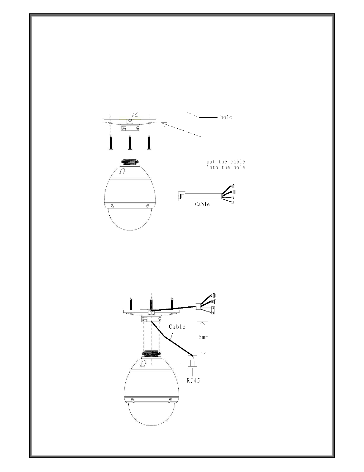
8.13 Install the Speed dome mounting base
(1) Cut three holes in the ceiling.
(2) Put the cable through the Speed dome mounting base.(Fig.2)
(3) Let the RJ45 left about 15mm from the Speed dome mounting base. (Fig.3)
(4) Mount the Speed dome mounting base with three screws (4*35 type) on the ceiling.
(5) Connect the RJ45 with the bottom of the speed dome.
(6) Put the waterproof film into the bottom of the speed dome closely.
(7) Put the thread connector into the Speed dome mounting base and then turn left, lock the screws of the
thred connector to connect the Speed dome mounting base closely (Fig.4).
Fig.2

15
Fig.3
Fig.4
8.2 Wall Bracket Installation (Option)
8.21 Setting Protocol and ID
(1)Disassemble the glass Hood and the black Hood in the dome housing by the screwdriver, change the
switch “S1” to set the ID of this speed dome and change the switch “S2” to set the protocol. The detail can see
the 3.ID SETTING and the 4.PROTOCOL SETTING
(2) Assemble the glass Hood and the black Hood in the dome housing again.
8.22 Install the Wall Bracket
(1) Cut Four holes on the Wall.
(2) Put the cable through the hole of the panel of the wall bracket (Fig.5)
(3) Lock the panel with four screws (3*10 type) on the wall bracket (Fig.6)
(4) Connect the RJ45 with the bottom of the speed dome.
(5) Put the waterproof film into the bottom of the speed dome closely.
(6) Put the speed dome into the groove and turn left, lock the screws to connect the panel of the wall
bracket (Fig.7).

16
Fig.5 Fig.6 Fig.7
How to enter the menu of zoom module?
1. To execute the order CALL+64+ENTER into the menu.
2. Then you will see the menu of the module
Main Menu ( Page 1. )
S E T U P M E N U ( 1 / 3 )
W H I T E B A L A N C E I R I S
A G
C ・ S E N S B A C K L I G H T
E N H A N C E R
Z O O M ・ F O C U S
H / V R E V E R S E
T I T L E
P R E S E T
Main Menu ( Page 2. )
S E T U P M E N U ( 2 / 3 )
M O T I O N D E T E C T P O S I T I O N
G A M M A

17
P O W E R O N
M A S K
O S D
Z O O M + A F
L A N G U A G E
C O M M ・ I D
Main Menu ( Page 3. )
S
E T U
P
M E N
U
( 3 / 3 )
C R O S S L I N E
F R E E Z E
P O S I / N E G A
Sub Menu
White Balance
W H I T E B A L A N C E
C O L O R O F F O N
A U T O
W B
A T W R - - - ■ - - B A W B R - - - ■ - - B
G A I N
R - Y - - - - ■ - - - B - Y - - - - ■ - - -
This is used to control the color ON/OFF and white balance and the gain rate of RED & BLUE
color.
1. 「COLOR」selector:OFF is monochrome image,ON is normal color image,AUTO is at low
light AGC up, display image will be auto change to monochrome image.
2. 「WB」White balance control:ATW is Auto trace white balance,can be adjust offset level.
AWB is One push white balance. Push [menu] key「AWB」will start flicker, until flicker stop it will
lock the current color temperature at the same time.
3. 「GAIN」:The gain rate of R-Y & B-Y can be adjusted separately.
IRIS
I R I S

18
P E A K O F F O N A ■ - - - - - P
A L C
A U T O - - - ■ - - - F I X - - - ■ - - -
A E S A U T O - - - ■ - - -
F I X O F F
This is used to control the iris & shutter speed of the lens. It included 3 items “PEAK”, “ALC”,
“AES”.
1.「PEAK」is used to control the reaction of auto iris, which is based on the average light of
picture signal or the light rate of the peak.
2.「ALC」is used to select AUTO or FIX. Adjust IRIS level.
3.「AES」is used to select electronic shutter be AUTO or FIX function, at AUTO mode can be
adjust AES level,at FIX mode can be selector shutter speed at below, [OFF],[1/100sec]
,
[1/120sec],[1/250sec], [1/500sec],[1/1000sec],[1/2000sec],[1/4000sec],[1/10000sec]
AGC・SENS
A G C ▪ S E N S
A G C A U T O - - - ■ - - - S E N S A U T O ■ - - - - - -
This is used to select「AGC」and「SENS」function.
1.「AGC」:To adjust auto gain control, 0dBb~24dB 9 steps adjustable.
2. 「SENS」: For low light application: 0 Frame,6 Frame,12 Frame,16 Frame,18 Frame,
22 Frame,24 Frame,30 Frame,36 Frame, 9 steps adjustable.
BACKLIGHT
B A C K L I G H T
O F F
O N
A R E A
S E N S L O W - - - - ■ - - - H I
This is used to control “BLC” (Back Light Compensation),
1.「BLC」ON / OFF selector. Selector「ON」has 2 sub-items:「AREA
」,「
SENS」.

19
2.「AREA」: 48 BLC zones can be set separatly. According to the mask area (BLC zone) signal
to decide the iris and shutter speed.
3.「SENS」:Is used to enhance the BLC effect.
ENHANCER
E N H A N C E R
H ▪ G A I N - - - - - - ■ - - -
V ▪ G A I N - - - - - - ■ - - -
This is used to enhance the compensation of the picture quality.
1.「H • GAIN」:Horizontal Compensation
2.「V • GAIN」:Vertical Compensation
ZOOM・FOCUS
Z O O M ▪ F O C U S
D I G I T A L Z O O M O F F
Z O O M S P E E D - - - ■ - -
F O C U S S P E E D - - - ■ - -
Z O O M W I D E T E L E
F O C U S
M A N U A L I N F N E A R
A U T O
This is used to control the montion of the lens, included “Digital ZOOM” ON/OFF and times
set function.
1.「Digital ZOOM」selector:OFF、X2、X4、X6、X8、X10.
2.「ZOOM Speed」:Set the speed of the zoom.
3.「FOCUS Speed」:Set the speed of focus.
4.「ZOOM」:Lens ZOOM adjust WIDE / TELE

20
5.「FOCUS」:AUTO / MANUAL setting
H/V REVERSE
H / V R E V E R S E
H ▪ R E V E R S E O F F O N
V ▪ R E V E R S E
O F F O N
This is used to select image「Horizontal Reverse」and「Vertical Reverse」function.
1.「H.REVERSE」:Horizontal Reverse (Mirror) ON/OFF
2.「V.REVERSE」:Vertical Reverse (Up-side down) ON/OFF
TITLE
T I T L E
0 1 2 3 4 5 6 7 8 9 A B C D E F G H I J K L M
N O P Q R S T U V W X Y Z
a b c d e f g h i j k l m
n o p q r s t u v w x y z
□
:
;
' " . , < > ( ) [ ] { } ┌ ┘ ─ * /
U P
D O W N
This is used to set up the ID figures & position on the screen. (Title setting)
1.TITLE start position selector.
2.TITLE Character selector.
3.TITLE display position UP or DOWN selector.
PRESET
P R E S E T
O F F O N
I N I T I A L
O F F
O N
P H A S E
O F F
O N
─ - - - - - - ■ - - - - +

21
This is used to select the camera go back to “PRESET”, “INITIAL”, “PHASE” condition
1.「PRESET」:Set to ON camera will be reset and set to default data.
2.「INITIAL」select:Set to ON lens is action,Set to OFF lens is not action.
3.「PHASE」adj select:Set to OFF ext-sync is disable,Set to ON ext-VD sync is enable,(EXT-VD
signal must be input)
4. PHASE set to ON sync-phase adjustment.
MOTION DETECT
M O T I O N D E T E C T
O F F O N
A R E A
T I M E 1 0 S E C
3 0 S E C
6 0 S E C
S E N S L O W - - - ■ - - - HI
This is used to select the montion detcet function.
1. Motion detect ON / OFF select.
2. Motion detects area select.
3. Motion detects output time select.
4. Motion detect sensitive adjust.
POSITION
P O S I T I O N
A L A R M N O = 0
F R E E Z E
O F F
O N
P O S I T I O N
N O = 1
Z O O M S P E E D - - - ■ - -
F O C U S S P E E D - - - ■ - -
Z O O M W I D E T E L E
F O C U S I N F N E A R
This is used to set「ALARM-IN」function,either「ALARM POSITION」or「IMAGE FREEZE」.

22
1.「ALARM NO.」:Set alarm position(1~64),if set to (0) alarm position is not enable.
2.「Freeze」:Set ON mode,「ALARM-IN」is freeze trigger input.
3.「POSITION」:The alarm position have 64 steps (position) can be programed.
By this program,the zoom & focus may go to the exactly position where is programed.
GAMMA
G A M M A
T Y P E 1
T Y P E 2
This is used to select the camera gamma correction.
「
GAMMA」select:TYPE-A gamma is 0.45, TYPE-B gamma is 1.0
POWER ON
P O W E R O N
B L U E B A C K O F F
O N
P O S I T I O N
O F F
O N N O = 1
This is used to select the camera power on state.
1.「BLUE BACK」: Set to OFF camaer power on initial is normal display, Set to ON camaer
power on initial is display blue back.
2.「POSITION OFF」: Camera power on lens position is current position.
3.「POSITION ON」: Camera power on lens position is go to the designation position(1~64).
MASK
M A S K
P O S I T I O N N O = 1 M A S K N O = 1
O F F O N
H - S T A R T = 2 0
H - E N D = 2 0 V - S T A R T = 2 0 V - E N D = 2 0 C O N N E C T O F F O N

23
This is used to select mask area size and position for each setable lens position.
1. Lens position no. select(1~64)
2. MASK NO. select(1~4)
3. MASK area display ON / OFF select.
4. Hor. direction start position.
5. Hor. direction end position.
6. Ver. direction start position.
7. Ver. direction end position.
8.ZOOM action to link mask area, ON / OFF select.
OSD
O S D
P O S I T I O N O F F
O N
M O T I O N O F F
O N
Z O O M ▪ M A G O F F
O N
This is used to select on screen display ON / OFF select.
1. POSITION NO. display ON / OFF select.
2. MONTION action display ON / OFF select.
3. ZOOM times display ON / OFF select.
ZOOM+AF
Z O O M + A F
Z O O M + A F
O F F O N
A F S L E E P
O F F O N
This is used to select an occasion for auto focus action.
1. ZOOM stops time execute lens focus once, action OFF / ON select.
2. AF Sleep function ON / OFF select.
(As show screen stillness about 5 minutes cameras come into AF Sleep mode namely, as
screen has bigger change time come back again act for normal mode namely.)
LANGUGE
L A N G U A G E
E N G L I S H
C H I N E S E

24
J A P A N E S E
This is used to select OSD manu display language.
OSD display language select, ENGLISH / CHINESE (Simp.) / JAPANESE
COMM・ID
C O M M ▪ I D
C O M M ▪ I D = 1 M O D E
1 : 1
1 : N
This is used to select communcation ID and mode.
1. Communication ID number's set.(Enactment supply controller identification camera uses
ID number.)
2. MODE choice
1:1 : One controller to control one Camera.
1:N : One controller to control many Cameras.
CROSS LINE
C R O S S L I N E
O F F O N
This is used to select the cross line display ON / FF.
Cross line ON/OFF select,set ON cross line display,set OFF cross line is hidden.
FREEZE
F R E E Z E
O F F O N
This is used to set「IMAGE FREEZE」.
「
Freeze」:Set ON mode,「ALARM-IN」is freeze trigger input.
POSI / NEGA
P O S I / N E G A
P O S I

25
N E G A
This is used to select image「Positive」and「Negative」function.
「POSI/NEGA」:Image positive & negative select.
 Loading...