

Page 1

Dust Networks
D2120 Evaluation Kit
Quick Start Guide
Page 2

Trademarks
Dust Networks, the Dust Networks logo, and SmartMesh are trademarks of Dust Networks, Inc. All third party brand and product names
are the trademarks of their respective owners and are used solely for informational purposes.
Copyright
This documentation is protected by United States and international copyright and other intellectual and industrial property laws. It is solely
owned byDust Networks, Inc. and its licensors and is distributed under a restrictive license. This product, or any portion thereof, may not
be used, copied, modified, reverse assembled, reverse compiled, reverse engineered, distributed or redistributed in any form by any means
without the prior written authorization of Dust Networks, Inc.
RESTRICTED RIGHTS: Use, duplication, or disclosure by the U.S. Government is subject to restrictions of FAR 52.227-14(g) (2)(6/87)
and FAR 52.227-19(6/87), or DFAR 252.227-7015 (b)(6/95) and DFAR 227.7202-3(a) and any and all similar and successor legislation
and regulation.
Disclaimer
THIS DOCUMENTATION IS PROVIDED “AS IS” WITHOUT WARRANTY OF ANY KIND, EITHER EXPRESSED OR IMPLIED,
INCLUDING BUT NOT LIMITED TO, THE IMPLIED WARRANTIES OF MERCHANTABILITY OR FITNESS FOR A
PARTICULAR PURPOSE.
THIS DOCUMENTATION MIGHT INCLUDE TECHNICAL INACCURACIES OR OTHER ERRORS. CORRECTIONS AND
IMPROVEMENTS MIGHT BE INCORPORATED IN NEW VERSIONS OF THE DOCUMENTATION.
EMI Warning
This equipment has been tested and found to comply with the limits pursuant to Part 15 of the FCC rules. These limits are designed to
provide reasonable protection against harmful interference in an appropriate installation. This equipment generates, uses, and can radiate
radio frequency energy and, if not installed and used in accordance with the instructions, may cause harmful interference to radio
communication. However, there is no guarantee that interference will not occur in a particular installation. If this equipment does cause
harmful interference to radio or television reception, which can be determined by turning the equipment off and on, the user is encouraged
to try to correct the interference by one or more of the following measures:
(1) Reorient or relocate the receiving antenna.
(2) Increase the separation between the equipment and receiver
(3) Connect the equipment into an outlet on a circuit different from that to which the receiver is connected.
(4) Consult the dealer or an experienced radio or television technician for assistance.
D2120 EVALUATION KIT QUICK START GUIDE
Page 3

Contents
1 About This Guide
Related Documents..........................................................................iii
Conventions Used..............................................................................iii
1 M2020 Evaluation Module
M2020 Evaluation Module ........................................................... 1
Connector P1.......................................................................................... 2
Connector P2.......................................................................................... 3
Serial Interface .................................................................................... 4
Power Supply......................................................................................... 4
Absolute Maximum Ratings........................................................ 4
Recommended Operating Conditions................................. 5
Wireless Specifications.................................................................. 5
Antenna ...................................................................................................... 5
Regulatory Information ................................................................ 6
2 SmartMesh Manager
Description............................................................................................... 7
Connections............................................................................................. 8
Technical Specifications................................................................ 8
Regulatory Information ................................................................ 9
3 Setting Up a Network
Setting Up the SmartMesh Manager ................................. 11
Setting Up the Network............................................................... 11
D2120 EVALUATION KIT QUICK START GUIDE i
Page 4

TABLE OF CONTENTS
ii D2120 EVALUATION KIT QUICK START GUIDE
Page 5

About This Guide
This guide provides information required to successfully demonstrate the capabilities of
the D2120 Evaulation Kit. It provides various pinout and connector information for
attaching sensors to a mote Evaluation Module and instructions for setting up a network.
Related Documents
The following documents are available for a SmartMesh Network:
• D2120 Evaluation Kit Quick Start Guide (this guide)
• SmartMesh Manager Application Programming Interface (API) Guide
• Mote Integration Guide
• SmartMesh Network Planning Guide
• SmartMesh Network Administration Guide
Conventions Used
The following conventions are used in this guide:
• Computer type indicates information that you enter, such as specifying a URL.
• Bold type indicates buttons, fields, and menu commands.
• Italic type is used to introduce a new term.
dNote: Notes provide more detailed information about concepts.
bCautions: Cautions advise you about actions that might result in a loss of data.
cWarning! Warnings advise you about actions that may cause physical harm to the
hardware or your person.
D2120 EVALUATION KIT QUICK START GUIDE iii
Page 6

CHAPTER 1 - ABOUT THIS GUIDE Conventions Used
Body.
iv D2120 EVALUATION KIT QUICK START GUIDE
Page 7
M2020 Evaluation
Module
This chapter provides specifications for the M2020 Evaluation Module (M2020-EVM)
provided in the D2120 Evaluation Kit. The M2020-EVM can be used as a reference
design for integrating an M2020 Mote into a self-contained device.
M2020 Evaluation Module
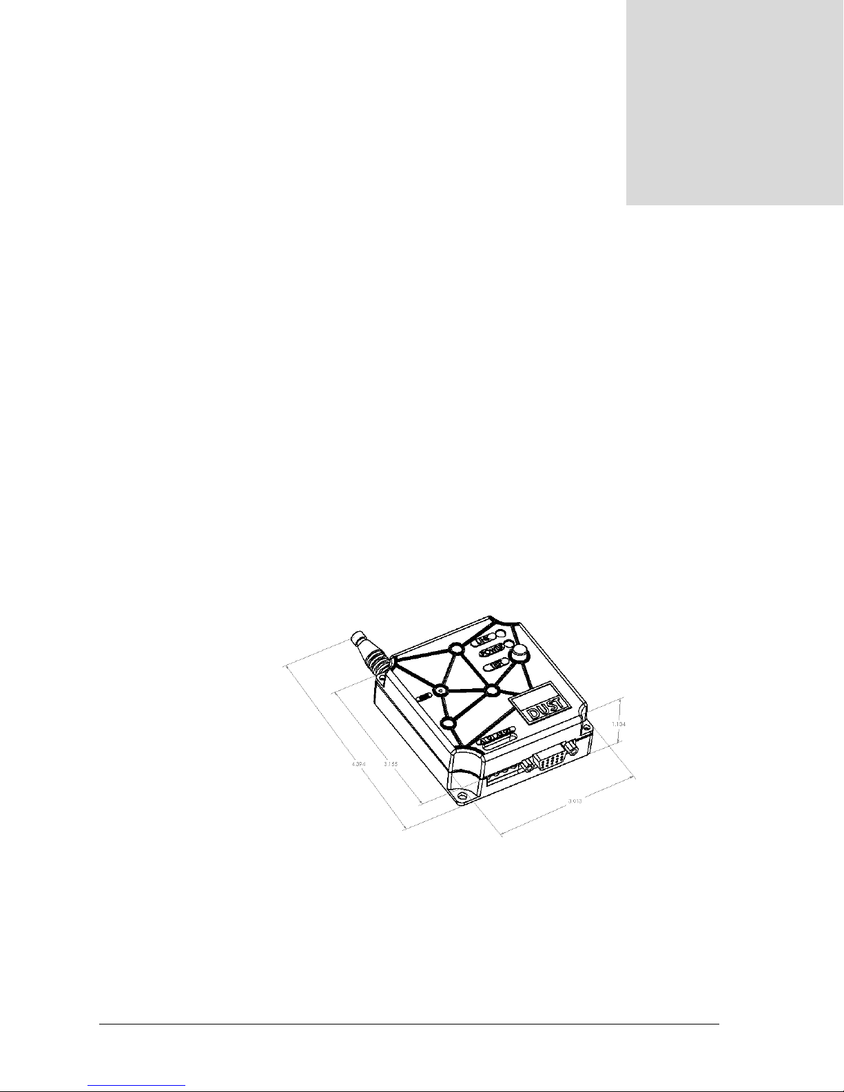
The M2020-EVM consists of an M2020-A Mote, packaged with an antenna, battery
holder, status LEDs, I/O connectors, and a recessed reset switch. The M2020-EVM
board is packaged in a plastic enclosure suitable for mounting on a wall or other vertical
surface.
1
Figure 1-1. M2020 Evaluation Module
D2120 EVALUATION KIT QUICK START GUIDE 1
Page 8
CHAPTER 1 - M2020 EVALUATION MODULE Connector P1
Connector P1
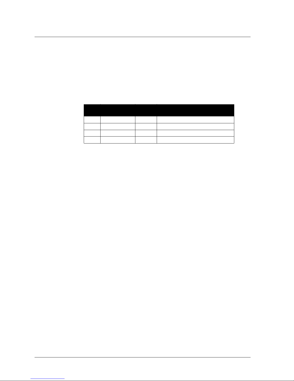
Connector P1 is a 4-position terminal block connector that accepts 12–22 AWG wire. It
assumes 0 to 5 V inputs, and contains internal filter circuitry for 60 Hz noise.
Table 1-1. P1 Connector Pinouts
Pin
Number Pin Name I/O Description
1 A1 I Analog input 1 (0–50)
2 GND I Ground
3 A2 I Analog input 2 (0–50)
4 GND I Ground
cWarning: Reverse biasing these inputs may result in damage to the device.
2 D2120 EVALUATION KIT QUICK START GUIDE
Page 9
Connector P2 CHAPTER 1 - M2020 EVALUATION MODULE
Connector P2
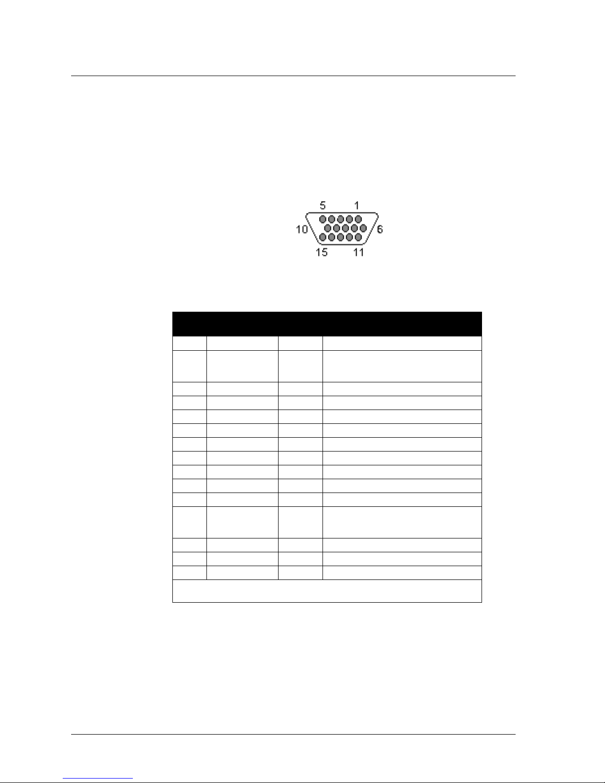
Connector P2 is an HD-15 female connector, as shown in Figure 1-2. It assumes
0 to 1.5 V analog inputs, and is unfiltered. All digital I/O are LVTTL (3 V) signaling.
Figure 1-2. HD-15 Female Connector
Table 1-2. P2 Connector Pinouts
Pin
Number
1TX OUART Transmit
2 D5 I/O Digital I/O 5 or SOF
3 D2 I/O Digital I/O 2
4 A7 I Analog input 7
5 A4 I Analog input 4
6 RX I UART Receive
7 D6 I/O Digital I/O 6
8 D3 I/O Digital I/O 3
9 GND I Ground
10 A5 I Analog input 5
11 D7 I/O Digital I/O 7
12 D4 I/O Digital I/O 4 or CTS
13 D1 I/O Digital I/O 1
14 A6 I Analog input 6
15 A3 I Analog input 3
Note: All I/O, including UART, are at LVTTL (3 V) signaling levels. An external
level converter is required for RS-232 communications.
Pin Name I/O Description
(see the Mote Integration Guide,
Appendix C)
(see the Mote Integration Guide,
Appendix C)
cWarning: Reverse biasing these inputs may result in damage to the device.
D2120 EVALUATION KIT QUICK START GUIDE 3
Page 10
CHAPTER 1 - M2020 EVALUATION MODULE Serial Interface
Serial Interface
Connector P2 provides a flow-controlled serial interface with timing information (using
TX, RX, CTS, and SOF), as described in the Mote Integration Guide, Appendix C.
Serial port settings are 9600 bps, 8 data bits, no parity, 1 stop bit.
Power Supply
The M2020-EVM board is powered by a pair of L91 1.5 V AA lithium batteries (or
equivalent), and comes with a standard double AA battery holder. The M2020-EVM
does not contain a power switch. Units are tested and shipped in deep sleep mode. To
place the device into deep sleep, short pins 1 and 6 on P2, and reset the M2020-EVM.
The status LEDs should remain off, and the device remains asleep until it is reset. To
activate the unit, press reset with pins 1 and 6 unconnected.
Absolute Maximum Ratings
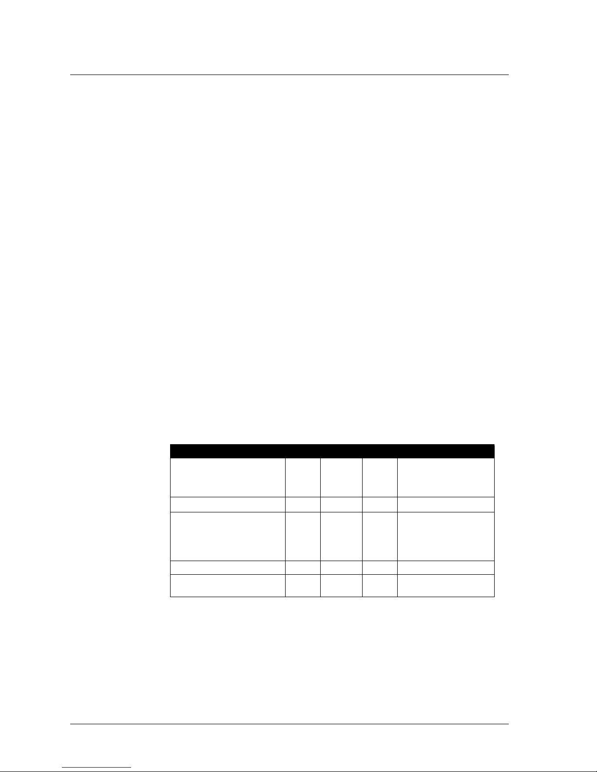
Table 1-3. Absolute Maximum Ratings
Parameter Min Max Units Condition
Supply voltage
V
BAT (VCC
Voltage on any pin –0.3 V
Digital I/O current
Source
Sink
Total I/O
Storage temperature –40 +85 °C
Operating ambient
temperature
c
Warning: The M2020 Mote is an ESD-sensitive device. Use caution when handling
in order to prevent permanent damage to the device.
)2.73.6V
CC
–40 +85 °C
Referenced to GND
+0.3 V Referenced to GND
2
6
24
mA
mA
mA
4 D2120 EVALUATION KIT QUICK START GUIDE
Page 11
Recommended Operating Conditions CHAPTER 1 - M2020 EVALUATION MODULE
Recommended Operating Conditions
Table 1-4. Operating Conditions
Parameter Min Max Units Condition
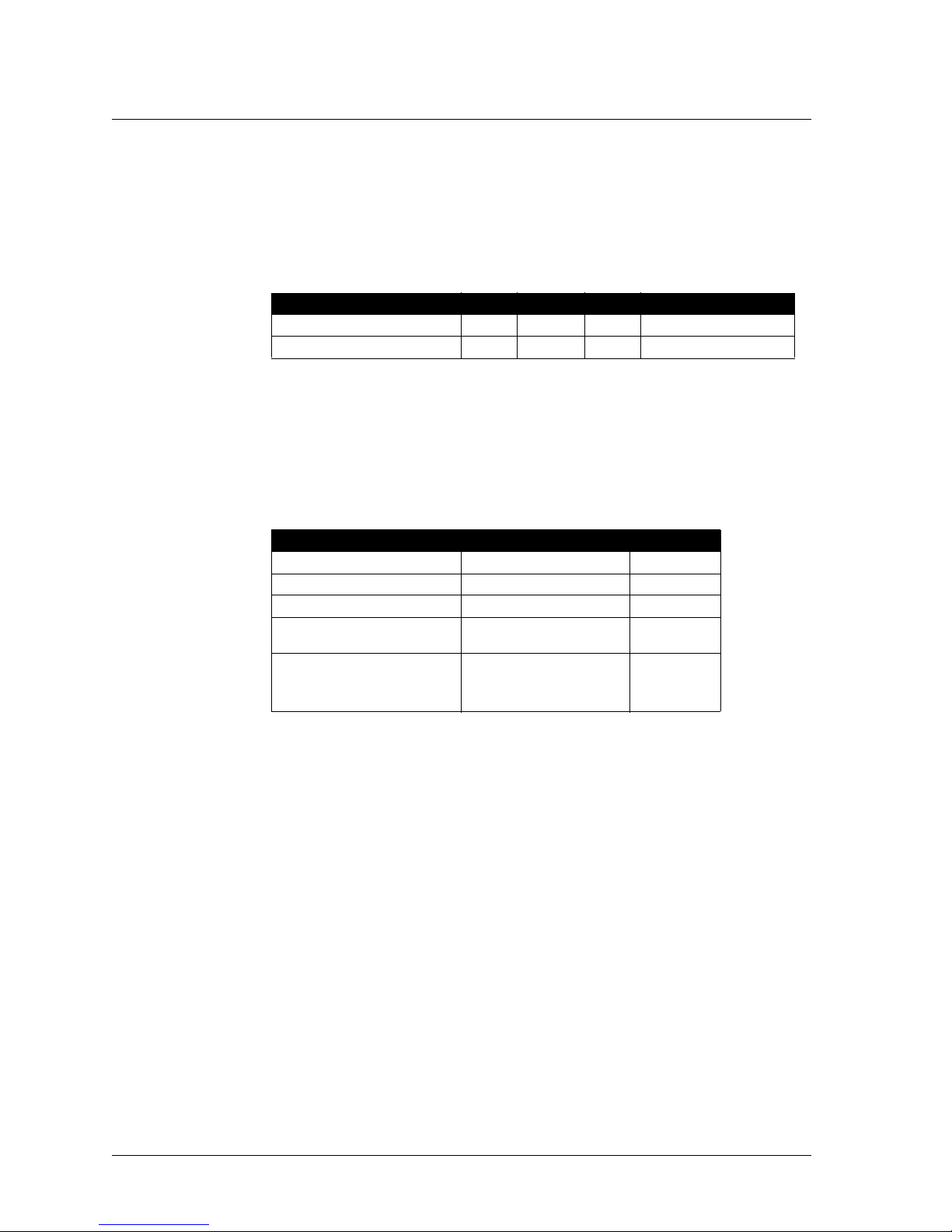
Analog input impedance 75 kΩ
Analog input capacitance 40 pF
Wireless Specifications
Table 1-5. Wireless Specifications
Parameter Max Units
Frequency Band 2400–2483.5 MHz
RF output power –3 dBm
Transmit data rate 250 kpbs
Receiver sensitivity
(at 15 dB SNR)
Range
Outdoors (1m elevation)
Indoors
–93 dBm
>100
10–30 typical
m
m
Antenna
Avoid handling the module by its antenna. For best results, place all devices so that the
antenna points to the ceiling. Devices placed close to the ground may have a
significantly reduced range. In the event of communications difficulties, try changing
the orientation of the module.
D2120 EVALUATION KIT QUICK START GUIDE 5
Page 12

CHAPTER 1 - M2020 EVALUATION MODULE Regulatory Information
Regulatory Information
The FCC ID: SJC-M2020EVM. This device complies with Part 15 o the FCC rules.
Operation is subject to the following two conditions:
(1) This device may not cause harmful interference.
(2) This device must accept any interference received, including interference that may
cause undesired operation.
bCaution: Unauthorized modification or changes not expressly approved by Dust
Networks™ Inc. could void compliance with regulatory rules, and thereby your
authority to use this equipment.
6 D2120 EVALUATION KIT QUICK START GUIDE
Page 13
SmartMesh Manager
This chapter describes the D2120 SmartMesh Manager provided in the D2120
Evaluation Kit. The D2120 is used to configure and control a network of M2020 motes,
and provides data and configuration information via an XML/RPC interface.
Description
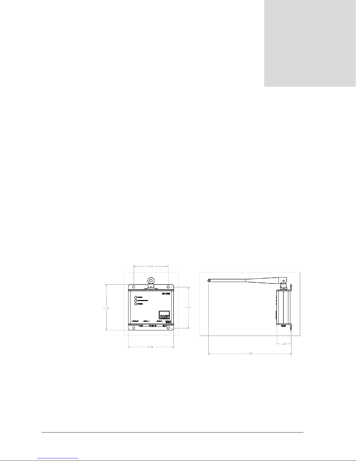
The D2120 SmartMesh Manager consists of a single board computer and an M2020
mote. The M2020 mote acts as a radio gateway between the single board computer and
the Dust Network. An API is provided to allow users to develop custom interfaces or
data logging applications. Refer to the SmartMesh Manager API Guide for further
information.
2
Figure 2-1. SmartMesh Manager (Top View) and Antenna (Side View)
D2120 EVALUATION KIT QUICK START GUIDE 7
Page 14
CHAPTER 2 - SMARTMESH MANAGER Connections
Connections
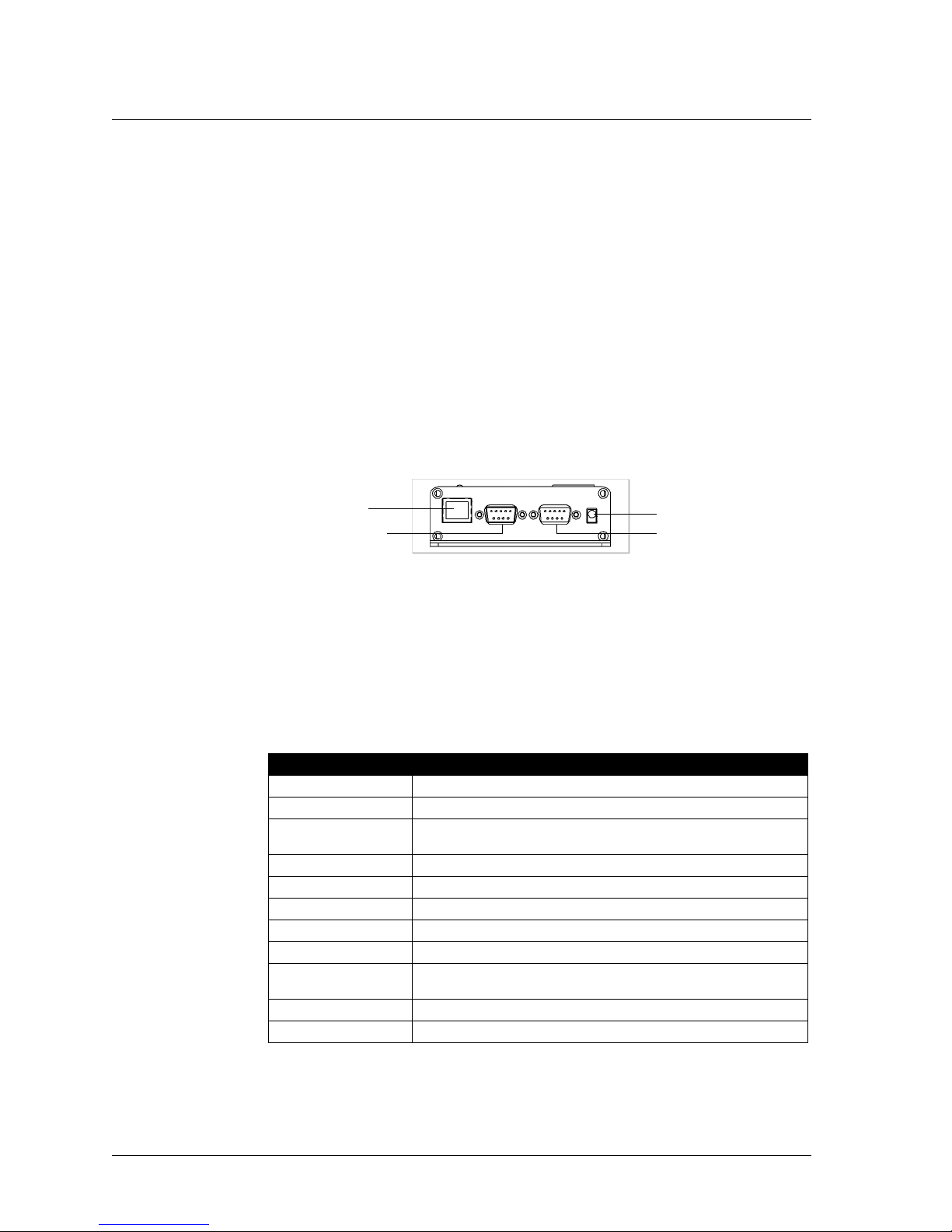
The D2120 SmartMesh Manager has the following ports available:
• 10/100 Ethernet port—Used for connection to a LAN or direct connection to a
computer using the cross-over cable provided in the D2120 Evaluation Kit. Refer to
the SmartMesh Manager Administration Guide for information on configuring the
IP address of the SmartMesh Manager.
• Serial 1 port (RS232)—Reserved for future connection. 115 kbps maximum. Not
flow controlled (TX, RX, ground only).
• Serial 2 port (RS232)—Command line interface (38400 bps, 8 data bits, no parity,
1 stop bit. Not flow controlled (TX, RX, ground only).
• Power—5 VDC, center positive, 2A.
10/100 Ethernet
Connection
Serial port 1 (DB9-M) Serial port 2 (DB9-M)
Power
Figure 2-2. SmartMesh Manager Connectors
Technical Specifications
Table 2-1. Technical Specifications for SmartMesh Manager
Category Description
Processor Intel PXA255, 400 MHz
Radio M2020 gateway mote
Radio operating
frequency
Transmit power –3 dBm
Receive sensitivity –93 dBm
Connectors 10/100 Ethernet, 2 RS232 (5 V) serial, 1 power
Power 5VDC, 2A max
Antenna Nearson 1/2 wave dipole
Range 10–30 m indoors (typical)
Environment –10 °C to +70 °C
API interface XML/RPC
2400–2483.5 MHz, DSSS and frequency hopping (FCC 15.247)
100 m outdoors
8 D2120 EVALUATION KIT QUICK START GUIDE
Page 15

Regulatory Information CHAPTER 2 - SMARTMESH MANAGER
Regulatory Information
The FCC ID: SJC-D2120. This device complies with Part 15 o the FCC rules. Operation
is subject to the following two conditions:
(1) This device may not cause harmful interference.
(2) This device must accept any interference received, including interference that may
cause undesired operation.
bCaution: Unauthorized modification or changes not expressly approved by Dust
Networks™ Inc. could void compliance with regulatory rules, and thereby your
authority to use this equipment.
D2120 EVALUATION KIT QUICK START GUIDE 9
Page 16

CHAPTER 2 - SMARTMESH MANAGER Regulatory Information
10 D2120 EVALUATION KIT QUICK START GUIDE
Page 17

Setting Up a Network
This chapter describes how to set up a D2120 Evaluation Kit in a simple sensor
network. For a more detailed explanation, see the Getting Started Guide that came with
your Evaluation Kit.
Setting Up the SmartMesh Manager
A Install the SmartMesh Console software.
B Connect Manager to the PC using the cross-over cable.
C Connect power to the Manager.
D If necessary, adjust the IP address of the PC to allow connection with the manager.
E Start Console.
F Connect to Manager.
G Go on to set up the network.
3
Setting Up the Network
A Power up one evaluation module by resetting it.
B Press the Test button on the module.
The green Power LED should turn on. If it does not, make sure that the batteries are
properly seated. The Link LED starts blinking when the module has found the
network. When the module joins the network, the Link LED remains on.
C Form the network by powering up additional modules (repeat steps 1 and 2).
D Use the Console to verify network connectivity. For more information about
configuring and managing the network, refer to the SmartMesh Network
Administration Guide.
D2120 EVALUATION KIT QUICK START GUIDE 11
Page 18

CHAPTER 3 - SETTING UP A NETWORK Setting Up the Network
12 D2120 EVALUATION KIT QUICK START GUIDE
 Loading...