

Dustless HEPA 16008 User Manual
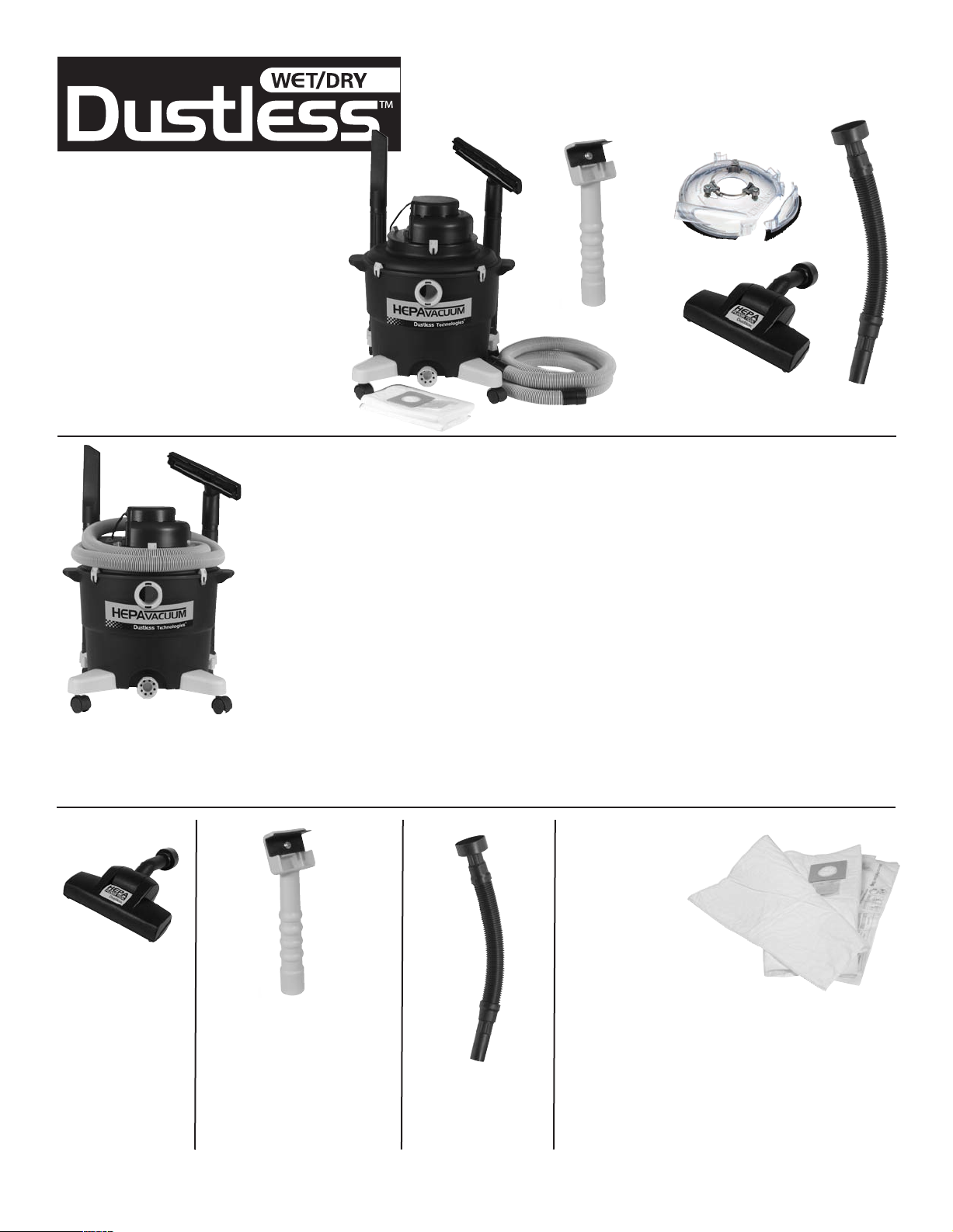
Kit # 16008 Includes:
1 - 16006 HEPA Wet/Dry Vacuum
1 - 13141 Micro Pre Filters (2 pkg)
1 - 13242 HEPA Floor Tool
1 - 60001 ChipBuddie
1 - D1835 5” Dustbuddie
1 - D5155 18” Adapter Hose
DUSTLESSTMEPA Lead-Safe
Compliance Kit
D1835 DustBuddie
16006 HEPA Vacuum
60001 ChipBuddie
13242 HEPA
Floor Tool
13141 Micro Pre Filters
Kit Model 16008
D5155 18”
Adapter Hose
Assembly - To install the legs and
accessory tray, undo the clips holding the intermediate cover in place
and set the cover and lid assembly
aside. Turn tank upside down. Front
legs are on either side of the drain
port opening. These front legs do
not have the small hooks on either
side. The back legs do have the
hooks. These hooks are for the
hose to rest on when in storage.
Align legs with openings provided
on bottom of the canister and slide
into place. The holes will only align
in proper position for front and back
legs. Insert black support screw
HEPA Vacuum - Complete
owners manual enclosed
with vacuum.
HEPA Floor Tool The HEPA Floor Tool
features a beater bar
as specified by EPA
to meet renovation
contractor certification
requirements. Fit
easily into HEPA
Vacuum attachments.
For a complete version of all owner’s manuals, please visits www.dustlesstools.com <http://www.dustlesstools.com> or call 800 568-3949.
ChipBuddie - Hook it to a hose
with the 18” hose adaptor and
scrape. Change blade by using a
Philips screwdriver. Works on
both sides of the blade for
collecting debris in both
directions. Use for scraping
paint or popcorn ceilings.
into hole and tighten screw with a
Phillips screwdriver.
Turn cleaner tank right side up.
Adapter Hose Attaches easily to
HEPA Vacuum hose.
Attach Accessory Tray
Align the three slots on the edge of
the accessory tray with the three
guides on the rear side of the tank
and press the accessory tray toward
the tank as you push the tray down.
The two locking tabs will slide
under the rim of the tank and catch.
By pushing the tray down and
toward the tank it will lock into
place.
Place intermediate cover and lid
assembly right side up and set
on top of the tank. Attach the
yellow clips from the tank onto
the intermediate cover.
The Lid Assembly with the vacuum
controls, motor, and filters are all
preassembled at the factory for your
Micro Pre-filter To install the Micro
Pre-filter, flip back
the lid tabs and
remove the lid.
Put the Micro Prefilter inside the
canister and slide
the opening of the
cardboard mounting collar over the input port on the inside
of the canister. Press firmly around all edges to ensure a
snug fit and air tight seal. Spread the Micro Pre-filter out,
making sure no part of it gets trapped under the edge of the
lid. Reinstall the lid and flip the locking tabs back
to the down position.
convenience. Maintenance and
replacement of filters is described
later in this manual.
Attach hose, wands and
cleaning accessories
Hose and accessories are stored
on the unit. The hose will loop
through the two outside holes of the
accessory tray and rest on the hooks
of the back legs as shown below.
For convenience, additional
accessories can be stored on
tray when not in use.
To Use Accessories
Push hose into tank port; twist hose to
tighten or loosen connection. The
wands and cleaning accessories
attach to hose in the same manner.
Installation Instruction
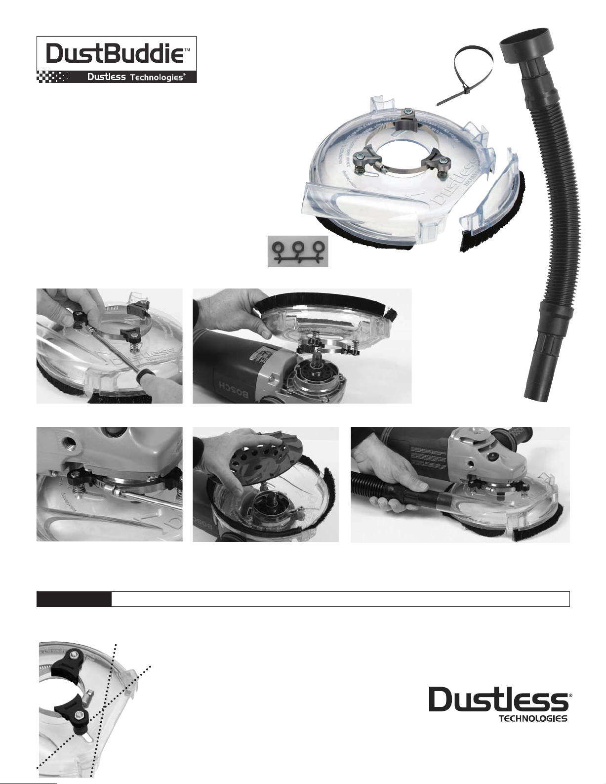
DUST COLLECTION SYSTEM FOR RIGHT ANGLE GRINDERS
D1835 5” Dust Buddie Complete set
D1850 7” Dust Buddie Complete set
A. 1 - D5115 S32 CLAMP 5 “ (D5125 S44 CLAMP for 7”)
B. 1 - D5150 RELEASABLE TIE
C. 1 - D1835.1 5" MAIN BODY W BRUSH (D1850.1 for 7”)
D. 1 - D1835.2 5" REMOVABLE CLIP W BRUSH (D1850.2 for 7”)
E. 1 - D1835.3 5" BRUSH SET (D1850.3 for 7”)
F. 3 - D1835.4 5" BOLT (D1850.4 for 7”)
G. 3 - D1835.5 5" NUT (D1850.5 for 7”)
H. 3 - D1835.6 5" ALUMINUM BRACKET (D1850.6 for 7”)
I. 3 - D1835.8 5" METAL WASHER (D1850.8 for 7”)
J. 3 - D1835.9 5" SPRING (SAME for 7”)
K. 1 - D1853 BUDDIE WASHER SET - (SAME for 7”)
L. 1 - D5155 18" DM BLK HOSE
Installation Steps:
K.
L.
B.
A.
G.
H.
D.
E.
C.
F.
J.
I.
Includes:
1 Clear polycarbonate
shroud w/brackets
and clamp
1 18” Flexible Hose
3 Washers
1 Removable clip
1 Releasable tie
1. Loosen band clamp. 2. Slip around grinder’s collar.
3. Center DustBuddie on the arbor
and tighten band clamp.
WARNING
Always make sure grinder is UNPLUGGED when removing or attaching front nose clip. Before use, refer to your tool manual for warnings and instructions.
4. Install grinding wheel.
(Use the washers provided to adjust
wheel slightly below the brushes. You
may also adjust the 3 screws if needed)
5. Insert Adaptor Hose in shroud port, then secure
the other end of the Adaptor Hose to the electrical
cord by wrapping a releasable tie around both.
Go to www.dustlesstechnologies.com for more information
Instructions for Crack Chasing/Tuckpointing Application
Cut
Line 1
Cut
Line 2
1. Tighten all 3 screws until bracket touches shroud.
2. Remove brushes. In the brush groove there is a plastic thin
rib that will have to be cut out in order to snap
coverplate in place.
3. Remove shroud clip, trim with band saw or cutting blade
as follows:
a. Trim on “Cut line 1” if cutting blade is directly in front of grinder
b. Trim on “Cut line 2”, if cutting blade is at a
45° angle
4. Install cutting wheel using washers provided to center the wheel
5. Snap cover plate in place (not included with grinding kit)
This product was inspected and packaged carefully before being shipped
from the factory. If you should happen
to need assistance during assembly or
operation, call 1-800-568-3949 for our
customer service department.
800.568.3949
dustlesstechnologies.com
Manual 082010
 Loading...