

Page 1
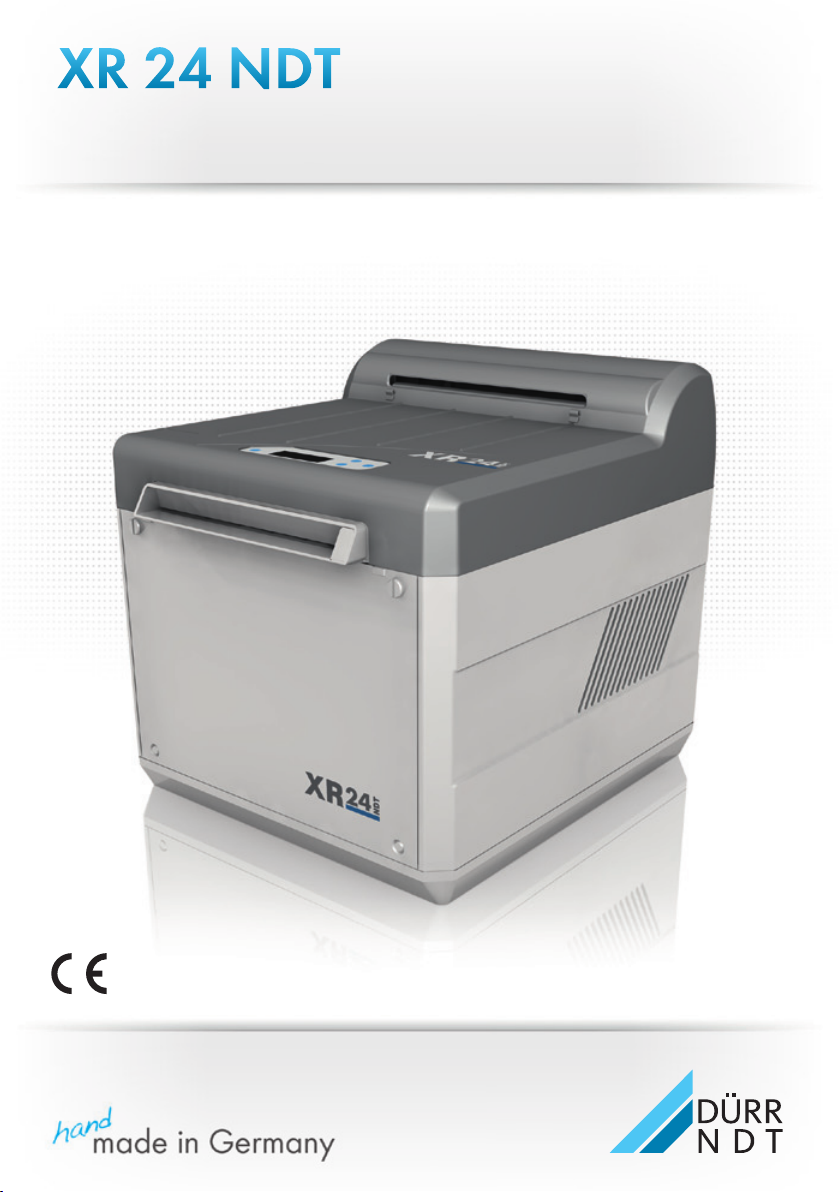
XR 24 NDT
Manual
EN
EN
9000-608-25/30
Page 2

EN
2
9000-608-25/30 2011/04/13
Page 3

Content
Important Informations
1. General . . . . . . . . . . . . . . . . . . . . . . . . . . 4
1.1 Official guidelines . . . . . . . . . . . . . . . . 4
1.2 Notes . . . . . . . . . . . . . . . . . . . . . . . . . 4
1.3 Disposal of appliance . . . . . . . . . . . . . 4
1.4 Correct Usage . . . . . . . . . . . . . . . . . . 4
1.5 Incorrect usage . . . . . . . . . . . . . . . . . 5
1.6 Product description . . . . . . . . . . . . . . 5
1.7 Connecting peripheral appliances . . . . 5
2. Safety . . . . . . . . . . . . . . . . . . . . . . . . . . . 5
2.1 General notes on safety . . . . . . . . . . . 5
2.2 Electrical safety instructions . . . . . . . . 5
3. Warnings and Symbols . . . . . . . . . . . . . 6
4. Delivery Contents . . . . . . . . . . . . . . . . . . 6
4.1 Special accessories . . . . . . . . . . . . . . 6
4.2 Disposable materials . . . . . . . . . . . . . 6
5. Technical Data . . . . . . . . . . . . . . . . . . . . 7
6. XR 24 NDT Functional layout . . . . . . . . . 8
7. Functional description XR 24 NDT . . . . 9
7.1 Arrangement of PCB (main board) . . . 9
Mounting
8. Set-up . . . . . . . . . . . . . . . . . . . . . . . . . . 10
8.1 Room for set-up . . . . . . . . . . . . . . . . 10
8.2 Set up options . . . . . . . . . . . . . . . . . 11
8.3 Set up . . . . . . . . . . . . . . . . . . . . . . . 11
9. Installation . . . . . . . . . . . . . . . . . . . . . . 12
9.1 Connecting water supply . . . . . . . . . 12
9.2 Waste water connection . . . . . . . . . . 12
9.3 Connection of developer and fixer
waste hoses . . . . . . . . . . . . . . . . . . . 13
10. Commissioning and first set up . . . . . . 14
10.1 Cleaning the unit . . . . . . . . . . . . . . . 14
11. Electrical connections . . . . . . . . . . . . . 15
12. Circuit diagram . . . . . . . . . . . . . . . . . . . 16
12.1 Operating section PCB . . . . . . . . . . 16
12.2 Controller section PCB . . . . . . . . . . 16
12.3 Performance functions PCB 230 V . .17
13. Commissioning and first set up . . . . . . 18
13.1 Settings / Service operation for
the Service Technician . . . . . . . . . . . 19
13.2 Check temperature of the developer 20
14. Transport . . . . . . . . . . . . . . . . . . . . . . . . 21
14.1 Remove the drainage hoses . . . . . . 21
14.2 Protection from damage . . . . . . . . . 21
Use
15. Operation . . . . . . . . . . . . . . . . . . . . . . . . 22
15.1 Mornings or before surgery begin . . 23
15.2 In the evening or after surgery
hours . . . . . . . . . . . . . . . . . . . . . . . 24
15.3 Operation interruption . . . . . . . . . . . 24
15.4 Film recommendations . . . . . . . . . . 24
16. Maintenance . . . . . . . . . . . . . . . . . . . . . 25
16.1 Change the chemicals . . . . . . . . . . . 25
Trouble-shooting
17. Tips for operators . . . . . . . . . . . . . . . . . 32
17.1 Fault message on display with
audible signal . . . . . . . . . . . . . . . . . 33
18. Tips for technicians . . . . . . . . . . . . . . . 34
19. Tips for Troubleshooting . . . . . . . . . . . 35
19.1 Before beginning work . . . . . . . . . . 35
19.2 Remove front panel . . . . . . . . . . . . . 35
19.3 Remove rear panel . . . . . . . . . . . . . 35
19.4 Remove side panels . . . . . . . . . . . . 35
19.5 After completing work . . . . . . . . . . . 35
19.6 Service operation plan . . . . . . . . . . 36
19.7 Replacing display unit . . . . . . . . . . . 38
19.8 Check the fusing of the unit . . . . . . . 38
19.9 Replacing process heater with
PTC-sensor . . . . . . . . . . . . . . . . . . 39
EN
2011/04/13 9000-608-25/30
3
Page 4

Important Informations
1. General
1.1 Official guidelines
This product has been subject to conformity
acceptance procedures and has been found to
conform to all requirements of the European
guidelines applicable.
EN
1.2 Notes
• The Installation and Operating Instructions
constitute a part of the appliance. They must
be made available to the operator. Correct
observance of the Installation and Operating
Instructions is is a basic requirement for using
the appliance properly and safely, and new
personnel must be instructed accordingly.
These Installation and Operating Instructions
must be handed over to any subsequent
owner or operator of this appliance.
• The safety of the operator and trouble-free
operation of the appliance can only be
ensured where original engineering
manufactured parts are used. Additionally,
only those accessories listed in the Installation
and Operating Instructions may be used or
parts or accessories expressly approved by
Dürr NDT. If accessories are used
manufactured by third parties, then Dürr NDT
can no longer provide any guarantee for safe
operation or correction functioning. No liability
on the part of the manufacture will be
accepted in the case that damage arises
through the use of non-approved accessories.
• Dürr NDT cannot be held responsible for the
appliance with regard to safety, reliability and
function where installation, reset, alterations,
extension or repairs were not carried out
either by or for Dürr NDT or by a third party
specifically approved by Dürr NDT, or if the
appliance is not used and operated according
to the instructions laid down in the Installation
and Operating Instructions.
• These Installation and Operating Instructions
accord with the features of the appliance and
the level of engineering at the time of first
introduction of the model. All circuits,
processes, names, software and appliances
quoted are protected under industrial property
rights.
• This translation of the Installation and
Operating Instructions has been carried out in
good faith. Liabilty for incorrect translation will
not be accepted. The accompanying German
version of these Installation and Operating
Instructions are to be used as reference; if you
have any doubt to the correct interpretation of
the instructions please consult your dealer.
• Any reproduction of these Installation and
Operating Instructions, or parts thereof, in any
medium whatsoever including electronic is
only permitted with the prior written approval
of Dürr NDT.
• Keep original packing for possible return of
the appliance to the supplier. Do not let the
packaging fall into the hands of children. Only
the original packing ensures optimum
protection for the appliance during transport.
If, during the period of guarantee, return of the
appliance is necessary, DürrNDT will not
accept claims for damage arising from using
incorrect packaging during transport!
1.3 Disposal of appliance
EU Directive(s) 2002/96/EG - WEEE (Waste
Electric and Electronic Equipment) of 27th
January 2003 and their current application in
national law states that products covered by the
above directive within the European Union must
be disposed of as special waste.
If you have any questions concerning the
correct disposal of this product please contact
Dürr NDT.
1.4 Correct Usage
The Dürr X-ray film developer XR 24 NDT is
designed exclusively for the automatic
development of X-ray films for industrial
applications.
Correct usage of the appliance involves exact
observance of the Installation and Operating
Instructions and adhering to the conditions
concerning set up, instructions for use as well
as maintenance.
Additionally, correct usage also involves
observing any local or national regulations
currently in force concerning health and safety
at work or the disposal of chemicals.
4
9000-608-25/30 2011/04/13
Page 5

1.5 Incorrect usage
Incorrect usage is understood to mean any
usage above or beyond the specific use laid
down. The manufacturer will accept no claims
for any damage or injury arising thereby. All risks
will be borne by the operator and/or owner.
1.6 Product description
The exposed film travels through several zones
or stages within the Dürr X-ray film developer
XR24 NDT: developer / fixer / rinsing and drying
zones.
After switching on the unit the developer and
fixer baths are heated up to the set temperature
of the baths, e.g. 28 °C (at 0.5 °C / min). After
this is complete the unit is ready for use and will
start automatically as soon as a film is inserted
and the film will be transported through the unit.
As soon as the blinking display "MACHINE IN
OPERATION" is extinguished a new film or 2
new films alongside each other can be inserted.
Once the film transport process is complete the
unit switches off automatically and goes into
Stand By mode.
1.7 Connecting peripheral appliances
Appliances may only be connected together or
connected to parts of other units where it has
been absolutely established that such
connections will not endanger the safety of the
operator and the environment will not be
affected in any negative way. If it is not clear
from the appliance documentation that such
connection is possible then the operator /
owner must establish this beyond reasonable
doubt, e.g. by contacting the manufacturer or
another expert, to ensure that the required
safety of the operator and the environment are
not put at risk.
2. Safety
2.1 General notes on safety
This appliance has been designed and
manufactured by Dürr NDT so that correct
usage will result in no danger to operator or
patient. However, we feel it is important to
describe the following safety measures in order
to remove any likelihood of danger.
• When operating this appliance all local and
national rules and regulations must be
observed! This appliance must not be
converted or altered in any way. Dürr NDT
accepts no liability claims where an appliance
has been converted or altered in any way. In
the interests of safe usage of the appliance
both operator and owner are responsible for
seeing that all relevant appliance are
observed.
• Installation must be carried out by a technical
expert.
• The operator must carefully check the
appliance for safety of function and the proper
working condition before every use.
• The operator must be trained in the correct
operation of the appliance.
• This product is not to be operated in an area
at risk through explosion, or an area with a
combustible atmosphere.
2.2 Electrical safety instructions
• The appliance may only be connected to a
correctly installed electrical socket.
• Before connecting to the electricity supply the
appliance must be inspected and checked
that the supply voltage and the supply
frequency correspond to that of the local
electrical supply.
• Before initial use and start-up the appliance
and all supply lines must be checked for any
signs of damage. Damaged supply lines and
connections must be replaced immediately.
• When using the appliance observe all the
relevant electrical safety procedures.
EN
2011/04/13 9000-608-25/30
5
Page 6
3. Warnings and Symbols
In the operating instructions the following
warnings and symbols have been used:
Information including preventative
measures to protect injury to
persons or damage.
Warning for high voltage.
Extra information concerning economic
usage of the appliance and other
EN
instructions.
CE-labeling without Notified Part
Number
Observe Installation and Operating
Instructions
Electrical supply switch ON / OFF
/ select parameters
confirm selection
Switch on supply
4. Delivery Contents
X-ray film developer XR 24 NDT
model 1734-08 (230 V ~, 50-60 Hz)
accessories, complete 1700-001-00
4.1 Special accessories
The following parts are not supplied as part of
the Delivery Contents clean.
Please order as required!
Water hose with Aqua-Stop ......... 1330-001-51
Regenerationunit (230 V) .............. 1734-820-00
Container, 20 liter for developer .... 1416-021-00
Container, 20 liter for fixer ............ 1416-011-00
Fuse 230 V, T 6.3A ....................... 9000-115-25
4.2 Disposable materials
NDT Starter-Set,
2x1.5 l developer, 2x1.5 l fixer .....CXB312A9940
NDT Fixer-Set, 4x1.5 liter ...........CXB313A5740
NDT Developer-Set, 2x6 liter ......CXB310A7540
NDT Fixer-Set, 2x6 liter ..............CXB310A7540
XR CLEANER NDT, 2 x Pack,
spray cleaner for
transport rollers ......................... CCB810C5540
Switch off supply
Mornings - open water tap
Evenings - close water tap
28 x 24 h every 4 weeks change
chemicals
drain chemicals
clean unit
6
9000-608-25/30 2011/04/13
Page 7

5. Technical Data
X-ray film developer XR 24 NDT
Model 1734-08
Voltage (V) 230
Frequency (Hz) 50-60
Current consumption (A) 4.0
Fusing (A) T 6.3
Output(W) 950
Heating
Bath heating (W) 400
Drying (W) 450
Warm-up time (min) ca. 20 (0.5 °C/min)
Film processing time (min) 5:30 - 10:00
Bath circulation process
Developer (l/min) ca. 1.8
Fixer (l/min) ca. 2.0
Water flow rate (l/min) 2
Water pressure (bar)
min. water pressure 2
max. water pressure 6
Tank volumes (l)
Developer, fixer je 5
Temperature ranges
Environmental conditions
for unit in operation +10 to +28 °C
Optimum image quality up to max. +28 °C
Storage and transport -10 to +60 °C
Relative humidity
for unit in operation max. 80 %
Storage and transport max. 95 %
Dimensions D=51 cm, W=42 cm, H=44 cm
Weight (kg) 25
Protection category IP20
Protection class I
Over voltage category II
Conformity certification CE-labeling
EN
2011/04/13 9000-608-25/30
7
Page 8
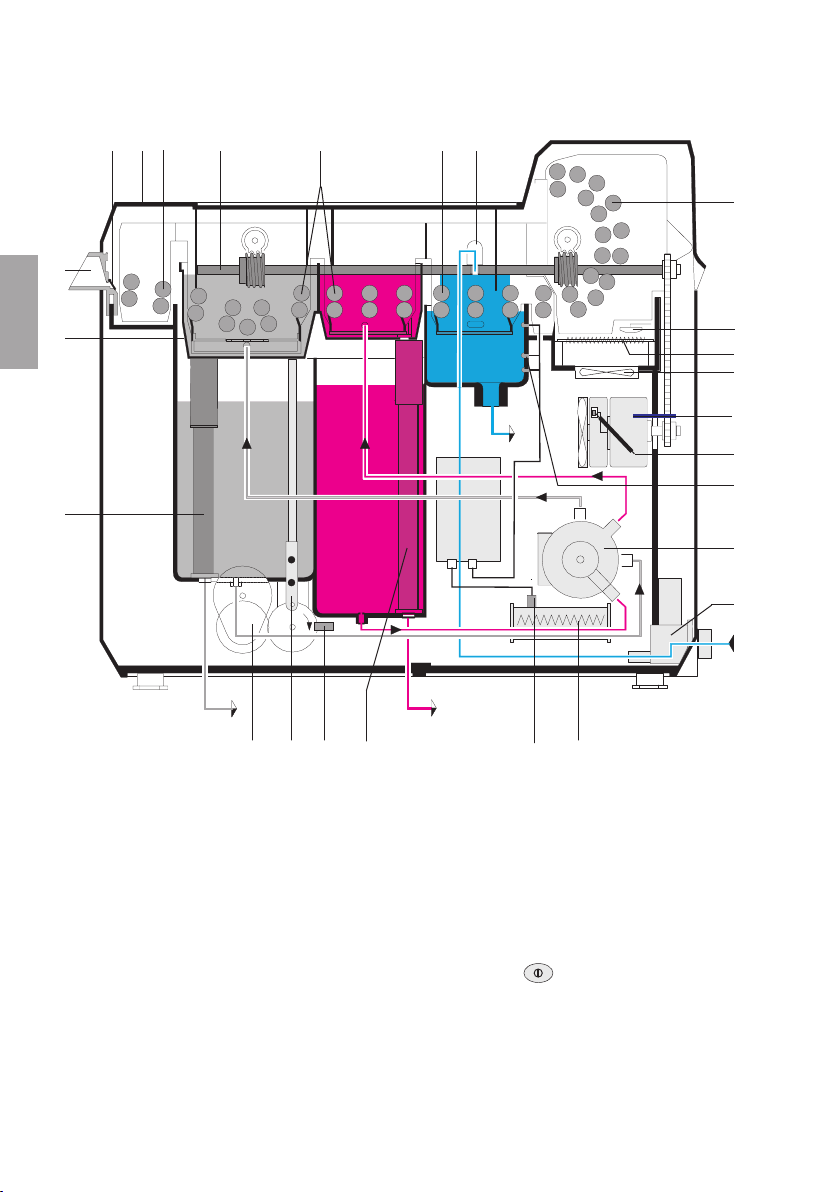
6. XR 24 NDT Functional layout
2 A 3 4 5 6 7
1
Stand By Position
8
EN
22
W
D
21
20 19 19a 18 17 16
1 Film insertion slot
2 Film feed flap
3 Film insertion slot roller set
4 Transport drive
5 Developer/fixer roller set
6 Rinse roller set
7 Water inflow
8 Dryer roller set
9 Safety switch for “dryer”
10 Dryer heater
11 Ventilation fan
12 Drive motor
12a RPM controller
13 Level indicator sensor “water”
14 Rotary pump (for developer and fixer)
15 Water intake valve
16 Process heater
17 PTC-sensing device
8
F
18 Overflow for fixer with drainage plug
19 Lifter
19a Light barrier for lifting bath
20 Lift motor
21 Overflow for developer with drainage plug
22 Lifting bath
D Developer bath
F Fixer bath
W Water bath
A Supply switch on display
9
10
11
12
12a
13
14
15
9000-608-25/30 2011/04/13
Page 9
7. Functional description XR 24 NDT
The display panel will light up once the main
power switch has been pressed
.The warming-up phase for the developer and
fixer baths will now begin. The waiting time until
the correct temperature is reached will be
displayed: "WAITING TIME . . MIN" (display
blinks). The unit will not unit during this warming
up period.
The bath circulation process runs in parallel to
the bath heating. The circulation precess
involves the rotatory pump (14) transporting the
chemicals from the developer and fixer baths
(tank volume of 5 liters each) to the lifting bath
(22).
Once the set temperature has been reached the
display lights "MACHINE FREE", i. e. the unit is
on "Standby"
As soon as the temperature falls by more than
0.5 °C below the set temperature, the process
heater and the rotary pump (14) switch on
again.
Insertion of a film causes the film feed flap (2) to
open and the display blinks: "MACHINE
OPERATING"
At the same time a signal is activated to lower
the lifting bath (22) and the water intake valve
(15) opens; the dryer heater (10), drive motor
(12) and rotatory pump (14) (for developer and
fixer bath circulation) start.
The processing time can be checked using the
RPM controller (12a).
Lifting and lowering of the lifting bath is
controlled by the rotation of the disc (driven via
the lift motor (20)) and is monitored by the
infrared light barrier (19a).
(mind.2 s)
If the waste water drainage becomes blocked, a
level indicator sensor (13) activates an audible
signal and the water intake valve (15) closes and
the flow of water is interrupted.
After complete insertion of a film the film feed
flap (2) closes. As soon as the blinking display
"MACHINE IN OPERATION" is extinguished a
new film or 6 intraoral films alongside each other
can be inserted.
If no further films are inserted after the film
process cycle (audible signal) then the lifting
bath (22) rises (Stand By Position) "MACHINE
FREE".
The drive motor (12), water intake valve (15) and
dryer heater (10) are switched off. In the Stand
By Position the developer and fixer roller sets (5)
are completely submerged in the chemicals.
This means that the build up of deposits on the
rollers can largely be avoided.
7.1 Arrangement of PCB (main board)
23 A Operating section
23 B Control functions
23 C Performance functions
23 A
23 B 23 C
EN
When the lifting bath (22) is lowered the film
passes between the rollers through the
developer and fixer baths, then through the
rinsing and the drying zones (8) at the set
processing time.
During film development water is fed along the
water inflow (7) into the rinse zone. The water
flows out to the waste water system. There is a
continuous flow of water at a rate of ca. 2 l/min,
at a pressure of 2 bar.
2011/04/13 9000-608-25/30
9
Page 10
EN
Mounting
8. Set-up
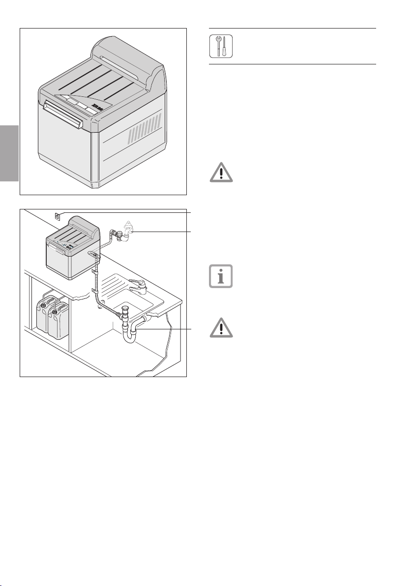
8.1 Room for set-up
• The developer unit XR24NDT may only be
set up in a dry, well-ventilated room.
• The room temperature in winter must not fall
below +10 °C or exceed +28 °C in the
summer
Do not set up the appliance in
direct sunlight! Danger of chemicals
1
26
27
28
2
overheating or premature exposure
of the film.
• The room for set up must be fitted with a
water tap (27) R3/4" with pipe ventilation,
waste water drainage (28) with ventilated
plastic siphon and an electrical safety socket
(26). It is also useful to have a wash basin or
sink near the developer unit.
Both the water tap (27) and the
electrical safety socket (26) should be
easily accessible for personnel.
• We strongly recommend set up of the
XR24NDT in a darkroom.
Interference
Portable radio transmitter/receiver
appliances (of rated power 2 W or
above) must not be operated within
a distance of 2 m of the XR 24 NDT
developer unit.
10
9000-608-25/30 2011/04/13
Page 11
D
8.2 Set up options
• Set up the developer unit on a horizontal,
stable and smooth, flat working surface at a
suitable working height.
• When feeding hoses downwards, the
working surface needs to have an opening
of ca. 7 x 10cm.
• Take into consideration the room required for
maintenace procedures and for adequate
ventilation of the unit:
at least 10 cm to the rear, ca. 50 cm free
space to left and right.
EN
4
8.3 Set up
• Set the box upright and cut loose the plastic
packing ties.
• Remove all small parts.
• Grasp the unit from the sides and set up as
appropriate.
• Set up the unit near the water supply, waste
29
water drainage and electrical safety socket
(max.1.5 m distant).
• Set up the unit with a very slight tilt, ca.
0.3°, towards the fixer bath (fig. 5).
Adjust the unit legs (29) using the spanner
(30) provided as necessary.
30
5
2011/04/13 9000-608-25/30
11
Page 12
EN
9. Installation
27
9.1 Connecting water supply
• Check firstly that clear, clean water is issueing
from the water tap (27)
When installing for the first time, let the water
flow thoroughly first!
• Because of the great differences in the
31
regional quality of water, a fine filter (32) must
first be installed between the water tap (27)
32
and water hose (34).
33
34
7
35
34
The fine filter (32) protects the flow
regulator of the water intake valve of the
appliance from impurities
• Close the water tap (27)
• Connect an elbow piece, 90° (33), to the
water tap (27), then fine filter (32) (arrow in
direction of flow) and insert double nipple
piece (31)
Check whether the coarse filter (34a)
and both seals (34b) are present in the
threaded connection piece of the water
hose (34).
• Connect the water hose (34) to the water
inflow connection (35) of the appliance
(threaded connection including coarse filter) and
fix to the double nipple piece (31).
12
34a
34b
8
9.2 Waste water connection
• Waste water connections must include a
siphon trap.
• Lay the waste water hose (36) with a
continuous incline to the siphon trap:
cut the hose to the correct length
36
9
9000-608-25/30 2011/04/13
Page 13
10
11
max. 3 cm
When laying the waste water
conections please be sure to
check the following:
- Avoid hoses from sagging!
- Avoid constriction or reduction
of hoses!
• Coat the ends of the hoses on the outside
with UHU-Plast
• Fix the screw socket (37) onto the hose and
onto the siphon trap (25) using hose clamp
(38)
• Secure the waste water hose with hose
clamp, screw and dowel.
37
38
9.3 Connection of developer and
25
fixer waste hoses
• Set the 10l-collecters (39) for developer
(black level indicator marker) and fixer (red
level indicator marker) under the appliance
so that they are clearly visible but free from
any possible spillage or knocking
• Lay the hoses (40) with continuous fall
40
• Cut the hoses to the correct length.
41
• Lead the hose for developer (black
markings) through the black lid (41).
• Securely screw the lid (41) onto the collecter
(39) for developer
• Secure the hose for fixer (red markings) in
the same way to the collecter for fixer
39
Empty the collecters when they
reach the level indicator marker
(43) - danger of overflow!
When disposing of developer and
fixer observe regional rules and
regulations!
In Germany, and in several other
countries, x-ray chemicals must
be disposed of as special waste.
EN
12
2011/04/13 9000-608-25/30
Fixer
43
41
39
13
Page 14
EN
11
13
10. Commissioning and
44
first set up
10.1 Cleaning the unit
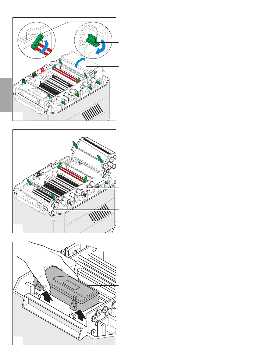
45
• Remove the lid.
• Remove the floating covers from the
developer and fixer baths
8
• Open the green catches (44) and stop clips
(45)
• Swivel the dryer packet (8) towards the rear.
• Remove the roller sets for water (6) and
developer/fixer (5).
8
• Swivel the display (90) upwards.
6
5
14
15
14
3
90
• The display can also be lifted upwards and
then to moved the left.
• Remove the roller set to the film insertion slot
(3).
90
9000-608-25/30 2011/04/13
Page 15

16
17
• On the side press the lever and remove the
lifting bath (22)
• Clean the roller sets, lifting bath and tanks
22
with a wet sponge.
"set up of chemicals"
and
"set up of roller sets"
see section USAGE
11. Electrical connections
This appliance is designed for
a supply voltage of 230 V (see
model identification plate). Before
connecting the mains power cable it
is absolutely vital to check that the
required supply voltage is available,
otherwise the connection could be
damaged. Use the Dürr mains cable
supplied.
The unit may only be operated when
it is closed - with sides and cover
in position - and connected to the
61
mains supply.
• Plug in the unit at the socket (61) in the unit
and the mains supply socket.
EN
2011/04/13 9000-608-25/30
15
Page 16

12. Circuit diagram
12.1 Operating section PCB
12.2 Controller section PCB
(see also section 23 C under section 7)
EN
23 B
16
23 A
12.1 12.2
R1 Temperature Sensor "Bath Temperature"
X5 "Water" level indicator sensor
U1 Cover light barrier
U2 Cover light barrier
U3 Lifting bath light barrier
1734-215-50
1700-221-00
M1 RPM regulater
U4 Film insertion slot-flap light barrier
9000-608-25/30 2011/04/13
Page 17

12.3 Performance functions PCB 230 V
(see also section 23 C under section 7)
23 C
EN
M1 Roller drive
M2 Ventilation fan
M3 Rotary pump
M4 Motor to lifting bath
R1 Bath heating
12.3
1734-216-50
2011/04/13 9000-608-25/30
R2 Dryer heater
Y1 Water intake valve
X1/X2 Appliance sockets
X3 Regeneration unit
17
Page 18

13. Commissioning and first set up
The developer unit XR 24 NDT has
3processing time alternatives, and is factory
set as follows:
10:00 min - Program REG. GRAIN
8:00 min - Program MTID. GRAIN
5:30 min - Program FINE GRAIN
Please note: X-ray films are not suitable for
archiving at this processing time.
When using film types which require a different
processing time, set the values according to
EN
the type of film being used.
- developer / fixer bath temperature 28°C
- dryer performance 30%
Films should emerge dry from the unit. The
dryer performance should be set according to
film type.
Program overview, see section Usage
The unit may only be operated when
it is closed - with sides and cover
in position - and connected to the
mains supply.
Every time the unit is switched on at the
main power switch the program "REG.
GRAIN" is automatically started, i.e.
after switching off there is an automatic
default selection of "REG. GRAIN"
Instructions concerning the operation
and display for the operator can be
found in section "USAGE", section 15.
A complete plan for service operation
can be found under Maintenance,
section 19.6.
Before developing the first film
the lifting tank of the developer
and fixer baths must be filled to
the overflow level, otherwise the
film development quality may be
impaired.
Always use cold water when making
up the chemicals.
The developer unit must never be
operated without its roller sets!
Without the roller sets it is possible that
the developer and fixer fluids will be
placed under pressure and will splash
vertically upwards out of the developer
unit.
Chemicals attack eyes and skin and
there is the possibility of severe
injury to the eyes.
Without the developer and fixer roller
sets there can be no circulation of
chemicals in the baths.
There is the danger of mixing of
chemicals.
Never operate the developer unit
without fluids (chemicals, water),
as this can lead to the heating
controller breaking down.
18
9000-608-25/30 2011/04/13
Page 19

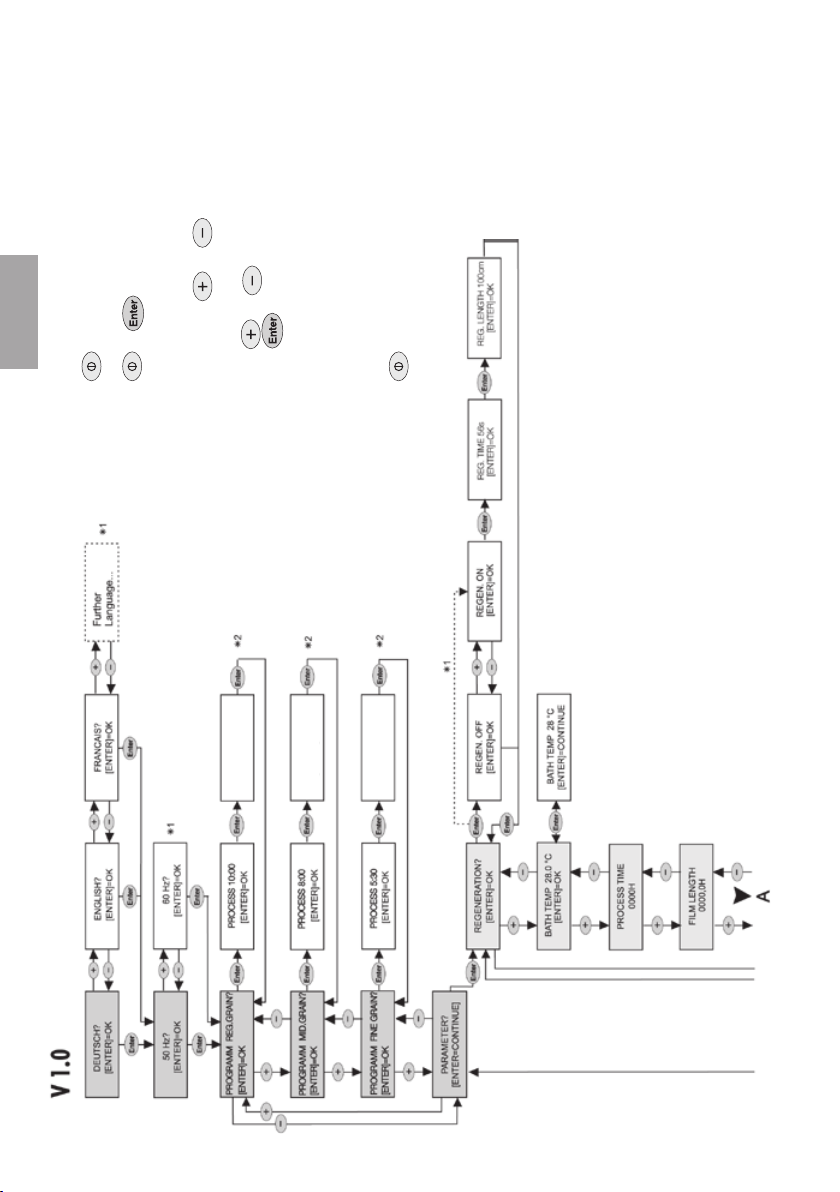
13.1 Settings / Service operation for the Service Technician
• Open the water tap.
• Check the unit and all connections for signs of
leakages
• Start the service operation
+ at the same time pressing (min. 4 s)
unit in service mode
• Select the service function
use button
to select service function
• Change settings
alter parameter values with
or
use 1 s to confirm new values
• *1 First to appear when switching on are set
language, frequency or value
*2 Factory settings
V 1.0
• End service function
Switch off unit using
power switch (press min. 2 s)
• Parameters such as language, electrical
frequency, etc. on the display can be set
according to the program plan :
EN
2011/04/13 9000-608-25/30
Change values using and in
5 and 5% steps, confirm with
DRYER 30%
[ENTER]=OK
DRYER 30%
[ENTER]=OK
DRYER 30%
[ENTER]=OK
19
Page 20

EN
21
13.2 Check temperature of the developer
The following procedure is applicable for
Germany. In other countries different
regulations may apply!
• Switch on the unit and wait for the
developer bath to raech operating
temperature, see also "Section 15.1 morning
or before surgery opening"
• In order to check the temperature of the
developer, switch off the unit.
• Unplug at the mains and remove all power.
• Close the water tap .
• Remove the lid.
• Measure the temperature of the developer
(front left at a depth of ca. 20 cm).
The temperature of the developer must be
+28 °C +/- 0,5 °C.
• Replace lid, plug in at the mains, open water
tap,
switch on unit so .
20
9000-608-25/30 2011/04/13
Page 21

22
14. Transport
Before transporting the developer unit please
note the following points:
27
31
39
63
The developer unit must only be
transported with completely empty
baths.
• Press the power switch to turn the unit off.
• Close the water tap (27)
• Unplug at the mains and remove all power.
• Unscrew the water hose (31) from the unit and
water tap (27).
• Empty the chemicals from the collecters (39)
into appropriate canisters (63).
• Drain the chemicals from the baths into
collecters (39), see section 16.1.1
• Clean the unit, see section 10.1
EN
23
24
2011/04/13 9000-608-25/30
14.1 Remove the drainage hoses
• Remove waste water hose (35).
• Loosen the hose from collecter (39) for
developer and fixer. Ensure that no drops of
chemicals spill or are splashed.
35
14.2 Protection from damage
• Protect the developer unit from any physical
load bearing and damage
• Ensure that the unit cannot move freely during
transport.
• Inform transport personnel.
39
21
Page 22

Power - switch
Confirm - key
, "Search menu
EN
Use
Program overview
The programs FINE GRAIN, MID. GRAIN and
REG. GRAIN are factory set (see below); your
Service Technician can set them, however, to
your individual requirements.
REG. GRAIN - Process time: t=10min
- bath-temperature: T=28 °C
- dryer performance: 30%
REG. GRAIN - Process time: t=8min
- bath-temperature: T=28 °C
- dryer performance: 30%
REG. GRAIN - Process time: t=5min
- bath-temperature: T=28 °C
- dryer performance: 30%
Films should emerge dry from the unit. The
dryer performance should be set according
to film type.
Every time the unit is switched on at the
main power switch the program "MID.
GRAIN", is automatically started, i.e. after
switching off there is an automatic
default selection of "MID. GRAIN"
Service / Fault message
see section 17.1 Fault message on display with
audible signal
SERVICE INTERVAL
REACHED!
Only when activated
by the Service
Technician!
22
BEFORE OPENING
DISCONNECT FROM
MAINS
FAULT WATER TOO
LOW!
FAULT WATER TOO
HIGH!
FAULT
ROLLER DRIVE
15. Operation
Before operation please note the following
points:
The developer unit must never be
operated without its roller sets!
Without the roller sets it is possible that
the developer and fixer fluids will be
placed under pressure and will splash
vertically upwards out of the developer
unit.
Chemicals attack eyes and skin and
there is the possibility of severe
injury to the eyes.
Without the developer and fixer roller
sets there can be no circulation of
chemicals in the baths.
There is the danger of mixing of
chemicals.
Never operate the developer unit
without fluids (chemicals, water),
as this can lead to the heating
controller breaking down. Regulate
the heating.
The unit should be switched on every
day in order to maintain constant image
quality.
Ensure that the ambient temperature of the
environment does not exceed that of the
developer bath!
Standby-Modus
Once the film exits the unit the Standby-Mode is
activated.
In Standby-Mode the unit is still operational and
simply awaits the next insertion of a film.
Before inserting a film check the program
selection!
9000-608-25/30 2011/04/13
Page 23

15.1 Mornings or before surgery begin
• Open the water tap.
• Switch on the unit:
•
Press the power on switch ca. 2 s
until an audible signal is heard
>> DURR NDT<<
T XR 24 NDT V.. T
WARM-UP PHASE
WAITING TIME .. MIN
<MID. GRAIN> 8:00
MACHINE FREE
t
<MID. GRAIN> 8:00
MACHINE BUSY
1 LED on display lights up. Lifting bath
automatically begins to move into the correct
position, ca. 30 s.
2 The unit initiates the warming-up phase until
the correct temperature of the developer bath is
reached. Warm-up time: 0.5 °C/min. During this
warm-up time a message blinks on the display
"WAITING TIME .. MIN"
3 As soon as the set temperature has been
reached the display panel lights up The unit
is ready for operation. A film can be
inserted.
The program MID. GRAIN is automatically
selected, where a different program is desired
then use key to change program to REG.
GRAIN or FINE GRAIN.
4 Before commencing developing every day run
two cleaning films through the unit.
5 Once a film has been insered the display
blinks: "MACHINE in OPERATION", as soon
as this message stops blinking then the next
film(s) can be inserted.
Two films can be inserted alongside
each other but within the markings, see
fig. 25.
EN
<MID. GRAIN> 8:00
REMAINING TIME ..MIN
<MID. GRAIN> 8:00
MACHINE BUSY
<MID. GRAIN> 8:00
t
MACHINE FREE
Changing the program:
see next page
2011/04/13 9000-608-25/30
t
6 The remaining developing time for the film(s) in
the unit is displayed (automatic countdown). An
audible signal is heard when the films exit.
7 If no further film is inserted the lifting bath
moves to the "Stand by"-Position
8 Unit in "Stand by"-Position message:
"MACHINE FREE" appears on display
Film material which has not been
exposed must not be placed on the
unit as the LCD-Display may lead to
incorrect exposure.
23
Page 24

Changing the program:
EN
DRYER 30%
[ENTER]=OK
DRYER 30%
[ENTER]=OK
DRYER 30%
[ENTER]=OK
If there is a fault message see
section 17.1 "Fault message on
display"
25
26
24
• 2 Films can be inserted together side by side.
Ensure that the marking goes into the
developer unit last.
• To obtain a fast control image change to
program "FINE GRAIN" (short process time:
5:30min).
15.2 In the evening or after surgery
hours
• Turn off the unit at the main power
switch.
•
Close the water tap.
15.3 Operation interruption
of more than 1 week:
• Drain off the chemicals.
• Clean baths and roller sets and leave to dry.
See 16.1.1
15.4 Film recommendations
Temperature of the bath(s): 28 °C
Dryer performance: 30 %
Manufacturer
Agfa Structurix D2, D3 Film 8
Agfa Structurix D3SC Film 8
Agfa Structurix D4-D8 Film 8
Kodak INDUSTREX AA400 Film 10
6
Kodak INDUSTREX DR50 Film 10
Kodak INDUSTREX High Speed
Kodak INDUSTREX M100 Film 10
Kodak INDUSTREX MX125 Film 10
3
Kodak INDUSTREX T200 Film 10
Fujifilm FUJI IX-25, FUJI IX-50 8
Fujifilm FUJI IX-80, FUJI IX-100 8
Fujifilm FUJI IX-150 8
Film type
HS800 Film
9000-608-25/30 2011/04/13
Processing
time
10
Page 25

27
28
16. Maintenance
60
Every 2 months
Change the chemicals,
Clean baths and roller sets,
make up chemicals
61
see section 16.1
• Check darkroom for stray lighting!
16.1 Change the chemicals
16.1.1 Drain the chemicals
91
• Press the power switch to turn the unit off.
• Remove the mains plug (61) from the electrical
safety socket.
• Remove cover (60).
• Check whether the collecter (39)
is empty, if necessary pour into the collection
canister (63)
It is extremely important that the
39
63
collecter is empty, otherwise there is the
dager of overflow, when the chemicals
are drained from the baths.
• Remove the floating covers from developer
and fixer baths, leave to dry and place to one
side.
• First remove the small plug from the lifting
bath, then the large plugs from the baths.
• Empty the collecter.
• Unscrew the lid of the collecter, hang the hose
ends in a neutral container.
This will prevent water from entering
either the collector or the canister
during cleaning.
EN
2011/04/13 9000-608-25/30
25
Page 26

EN
11
29
44
45
8
6
Cleaning and making up of chemicals
for the developer unit are based on the
use of DürrXR24NDT chemicals.
When using chemicals from third party
suppliers be sure to observe the
manufacturer's instructions!
16.1.2 Clean baths and roller sets,
• Open the green catches (44) and stop clips
(45)
• Swivel the dryer packet (8) towards the rear.
• Swivel the display upwards
• Remove the rinse and (6) film insert roller sets
(3)
26
3
30
• Lift the developer and fixer roller sets (5), tilt to
the side and let the chemicals run off
5
31
9000-608-25/30 2011/04/13
Page 27

32
33
Ù
Ù
• Place the roller sets in the sink, spray using
"spray cleaner and allow ca. 10 min to take
effect.
22
• On the side press the lever and remove the
lifting bath (22)
• Rinse the lifting bath (22) thoroughly under
warm, running water (min. 40 °C).
• Rinse the roller sets thoroughly under warm,
running water .
• Screw the large plugs (18, 21) into the baths.
• First fill the fixer bath with water, fig. 33.
• Then fill the developer bath with water.
• Place developer and fixer roller sets in
position.
Do not operate the developer unit
without developer/fixer roller sets.
Without developer/fixer roller sets
water will splash upwards out of the
unit as there will be no circulation
of the water in the baths. Danger of
eye injury!
• Close the green catches and clips.
• Swivel the display back into position.
• Replace cover (60).
• Plug in at mains (61), press power switch on.
• Start up unit, place cleaning film in film
insertion slot (1) until the film feed flap is
actuated, leave the film ca. 4 min in this
position.
• Let the unit run ca. 8 min (the hoses and
rotatory pump will be automatically cleaned).
• After ca. 8 min switch off the unit and
disconnect at the mains (61).
• Remove cover (60).
• Swivel the display upwards
• Open the green catches and clips.
60
• Lift the developer and fixer roller sets, drain
and remove.
• Unscrew the large plugs for developer (21)
and fixer (18) from their baths and drain the
water.
EN
34
2011/04/13 9000-608-25/30
1
27
Page 28

EN
35
36
28
37
16.1.3 Make up chemicals
• Screw the plugs for fixer (18) and developer
18
(21) into their baths.
• Replace the developer and fixer hoses back in
their collector.
21
• Put in place the separating barrier (52) between
developer and fixer baths.
Chemicals are dangerous to health
or aggressive. Irritate skin and eyes.
Danger of severe eye injury.
Damage irreversible.
52
When filling chemicals always wear
protective gloves and protective
glasses.
If there is any contact with the eyes,
immediately rinse thoroughly with
water and consult a doctor as soon
as possible.
Clean your hands thoroughly under
running water after finishing.
Please also refer to our special safety
brochure which you can find on the internet
at: http://www.duerr-ndt.de
or order it direct from Dürr NDT.
Usage of chemicals from third party
suppliers
When using chemicals from third party
suppliers please refer to the
manufacturer's instructions when making
up the chemicals.
All developer units which have already been
operated using chemicals from third party
suppliers can be converted to DürrXR24NDT
chemicals at any time.
Please note that the baths should be cleaned
thoroughly before changing chemical source
(refer to the manufacturer's instructions)
Usage of DürrXR24NDT chemicals
Dürr NDT developer and fixer chemicals
are based largely on natural ingredients.
Components such as Hydroquinol or
aldehyde are avoided as far as possible.
This reduces the accumulation of dirt in the unit
and thereby also reduces cleaning.
Concentrations
1.5l concentrated liquid mixed with water provide
5 l usable solution
6l concentrated liquid mixed with water provide
20 l usable solution
1.5 liters concentrated chemical in the baths
of the developer unit
1. Filling fixer bath (F) (fig. 36)
Pour the 1.5 liter bottle (fixer concentrated liquid)
carefully (avoid splashes which can lead to mixing
of chemicals) into bath and then fill to top
marking (54) with cold water.
9000-608-25/30 2011/04/13
Page 29

38
39
2. Filling developer bath (D) (fig. 37)
Pour the 1.5 liter bottle (developer concentrated
liquid) carefully (avoid splashes) into bath and
D
D
F
F
55
then fill to top marking (54) with cold water.
6 liters chemical concentrate in 20liter
container
Two clean and empty 20 liter canisters (55) are
required: for fixer and developer.
• Empty6 liter bottle of fixer (F) into canister and
fill with cold water to the 20 liter level.
• Empty 6 liter bottle of developer concentrated
liquid (D) into canister and fill with
to the 20 liter level.
• Place a cover securely on each container and
mix the contents.
1. Filling fixer bath (F) (fig. 40)
• Using a suitable container with a spout
opening (56) carefully pour some of the fixer
mixture into the fixer bath of the unit as far as
the upper marking (54) (avoid splashes which
might cause mixing of chemicals).
2. Filling developer bath (D) (fig. 41)
• Using the container (56) carefully pour some
of the developer mixture into the developer
bath of the unit as far as the upper marking
(54) (avoid splashes which might cause mixing
of chemicals).
• The remaining chemical mixtures should be
stored in the 20 liter containers in a dark place
56
until needed.
• Rinse the empty containers as well as the
filling vessel thoroughly with water and keep
for further use.
cold water
EN
40
2011/04/13 9000-608-25/30
41
29
Page 30

EN
42
• Remove separating wall or barrier.
• Place lifting bath (22) in position.
• screw in the small plug of the lifting bath.
60
16.1.4 Insert roller sets
The developer unit must never be
operated without its roller sets!
Without the roller sets it is possible that
the developer and fixer fluids will be
59
6
5
58
3
22
44
8
45
placed under pressure and will splash
vertically upwards out of the developer
unit.
Chemicals attack eyes and skin and
there is the possibility of severe
injury to the eyes.
Without the developer and fixer roller
sets there can be no circulation of
chemicals in the baths.
Danger of chemicals get into the
eyes and danger of mixing of
chemicals.
• Insert dryer packet (8) and swivel towards the
rear.
• Place roller sets for rinse (6), developer/fixer
(5) and film insertion slot (3) in place
respectively
Check that the guides slot into each other. If
necessary, rotate the toothed wheel of the
drive (58) until the worm screw correctly
engages with the transport drive
• Swivel the dryer packet (8) forwards.
• Close the green catches (44) and
stop clips (45)
• Place floating covers (59) for developer and
fixer baths in position
• Swing display back, i.e. in position.
• Replace cover (60). Be careful to ensure that
the lower lip of the lid aligns completely with
the guide of the housing cover
• Plug in at the mains.
30
9000-608-25/30 2011/04/13
Page 31

EN
2011/04/13 9000-608-25/30
31
Page 32

Trouble-shooting
17. Tips for operators
If it is not possible to solve the problems listed here with the aid of these Troubleshooting Tips,
then please call your Service Technician who will be glad to help.
Problem
EN
1. Completely not
operational
2. Film too bright
3. Film too dark • Set exposure times (where possible)
4. Yellowish-green
smear to film
Probable cause
• mains cable not correctly
plugged
• Cover not in position
• Power switched not pressed
long enough
• Developer used up
• Film exposure time on imaging
system too short
• Developer bath temperature
too low
• Film exposure time on imaging
system too long
• Developer bath temperature
too high
• Film not fixed correctly • Check whether fixer is still all right for
• Film developed using
program FINE GRAIN (with
process time 5:30)
Solution
• Plug mains cable in at electrical safety
socket and connector into rear side of
unit
• Place cover on correctly
• Press power switch min. 2 s
• Change chemicals (see section 16.1)
• Check regeneration levels.
• Set exposure times (where possible)
• Ask Service Technician to check and
reset if necessary.
• Ask Service Technician to check and
reset if necessary.
use: allow D4 films to lie ca. 56 s in fixer.
If the film becomes transparent then the
fixer is usable. If the smearing persists,
change the chemicals (see sec. 16.1ff)
• Choose a program with a longer
process time. Observe film processing
times
5. Dark smear or
streaks to film
6. Greenishbrown smear to
film
7. Film is streaky
32
• Light exposure into the
darkroom, e.g. through keyhole
• Darkroom lighting incorrectly
installed or pointing in wrong
direction
• Chemicals used up • Mix up new batch of chemicals
• Mixing of chemicals • Mix up new batch of developer
• Check the darkroom for stray ambient
light, if necessary black out light sources
• Lamps should only shine indirectly
chemicals
9000-608-25/30 2011/04/13
Page 33

Problem
Probable cause
Solution
8. General
background
fog to film
• Film stored too long
• Film incorrectly stored
• Developer bath-temperature
too high due to excessive room
temperature
• Check shelf life of film
• Observe correct storage conditions,
shelf life and manufacturer's instructions
on film packaging.
• Reduce the room temperature
17.1 Fault message on display with audible signal
Display
BEFORE OPENING
DISCONNECT FROM
MAINS
SERVICE INTERVAL
REACHED!
FAULT WATER TOO
LOW!
FAULT WATER TOO
HIGH!
FAULT
ROLLER DRIVE
further message to
come...
Either at beginning of or
during developer
process
After switching on the
unit
After insertion of a film
with delay of ca. 35 s
Either at beginning of
or during developer
process
Either at beginning of
or during developer
process
Cause
Safety relay on PCB
(main board) defect
Service interval
reached.
Water inflow to
water bath
interrupted
- Waste water
drainage blocked,
badly laid or not
ventilated
- Electrical bridging
caused by
accumulation of lime
scale on level sensor.
RPM-Signal from
motor interrupted,
possibly cable or
connector defect
Stray ambient light can lead to
pre-exposure of film material.
If necessary a separating wall or
barrier of lead protection can be
put up.
EN
Solution
Arrange maintenance by our
service technician.
Work can continue.
Before opening unplug at the
mains and remove all power!
Arrange maintenance by our
service technician.
Work can continue.
Check whether the water tap
is open and/or inflow hose is
connected
Remove blockage or check
whether the waste water
drainage-hose has been laid
correctly (water pocket).
Work can only be continued
after removal of problem
Arrange maintenance by our
service technician.
Problem during film development:
film is only carried at shortest
process time (5:30min) ! Too little
fixing process!
2011/04/13 9000-608-25/30
33
Page 34

18. Tips for technicians
see also section 19 Tips on Troubleshooting
Problem
1. Completely not
operational
2. Supply of
fresh water
interrupted
EN
3. Developer
temperature
not suitable
4. Film too bright
5. Film too dark
Probable cause
• Mains fuse defect
• Appliance fusing defect
• Water intake valve blocked or
defect
• Water inflow blocked
• Level indicator sensor has lime
scale (electrical bridging)
• Process heater defect
• Air in system, rotary pump not
vented. (Unit filled with water or
chemicals at ca. 20 °C starts
without warm-up.)
• Developer bath temperature too
low
• Temperature of developer too
high or process heater defect
Solution
• Check fuse and replace where necessary
• Check fuse and replace where
necessary (see section 19.8)
• Check valve and replace where
necessary (see section 19.10)
• Clean fine filter or coarse filter in water
hose
• Clean level indicator sensor (see section
19.12)
• Process heater and PTC-sensing device
need replacing (see section 19.9)
• Vent rotary pump by starting and
stopping the unit several times over a
short period. Electrical supply switch ON
/ OFF
• Check process heater and/or PTC-sensor,
replace if necessary (wsection 19.9)
• Measure the temperature and enter
"CALIBRATION?" in service menu
• Check process heater and/or PTC-sensor,
replace if necessary (section 19.9)
• Measure the temperature and enter
"CALIBRATION?" in service menu
6. Yellowishgreen smear to
film
7. Greenishbrown smear
to film
8. Film not
completely dry
• No chemicals in developer/fixer
roller sets (level in bath too low)
• No agitation or circulation of
chemicals
• Film not rinsed • Level indicator sensor in water bath has
• Dryer performance incorrectly
set
• Ventilation fan defect
• Heating defect
• Check the profile of seals and roller sets,
if necessary replace.
• Check rotary pump for possible signs of
air in hose
closed off the water intake valve - check
waste water drainage, if necessary clean
and realign hoses (see 9.2)
• Further possibilities, see above:
Solutions for 2. "No fresh water inflow"
• Reset the dryer performance
• Replace the ventilation fan
• Change the temperature control fuse
Fault message on display with audible signal see 17.1
34
9000-608-25/30 2011/04/13
Page 35

43
19. Tips for Troubleshooting
19.1 Before beginning work
60
• Turn off the unit at the main power
switch.
• Disconnect the plug (61).
61
• Remove cover (60).
• The housing panels required for working need
to be removed.
19.2 Remove front panel
• Swivel the display upwards
• Open the green catches (44) above roller
sets (3)
• Remove the roller set to the film insertion
slot (3).
• Unscrew the two grey rapid release catches
44
(68) from the front panel (56).
• Unscrew the 3 Philips screws (cross-headed)
(57) and remove the front panel (56).
45
19.3 Remove rear panel
• Open the green catches (44) and clips (45)
8
holding dryer packet (8).
• Swivel the dryer packet (8) towards the rear
and detach.
• Unscrew the 3 Philips screws (cross-headed)
(57) and remove the rear panel (67).
EN
1144
45
2011/04/13 9000-608-25/30
3
19.4 Remove side panels
• Remove front (56) and rear panels (67), lift the
side panels (55) upwards.
57
19.5 After completing work
• Replace all housing panels to their original
55
positions.
57
67
55
68
56
Never operate the unit if the panels
are not correctly positioned or
not screwed into place! The unit
is connected to power supply Danger of electric shock.
• Replace cover (60), plug in at the mains
35
Page 36
DRYER 30%
[ENTER]=OK
DRYER 30%
[ENTER]=OK
DRYER 30%
[ENTER]=OK
to select service function
EN
Switch off unit at main power switch
+ simultaneously press (min. 4 s)
(press min. 2 s)
unit in service mode
• Start service function
19.6 Service operation plan
•
use button
• Select the service function
• Change settings
or to alter parameters
Use 1s, to confirm new values
Use
Switch off unit using power switch
*1 The language selected, frequency or values
appear first on start up
*2 Factory settings
(press min. 2 s)
• End service function
36
9000-608-25/30 2011/04/13
Page 37

EN
2011/04/13 9000-608-25/30
37
Page 38

EN
46
19.7 Replacing display unit
91
• Disconnect the connector of the display cable
(92) from the PCB (main board) (86) and guide
through the opening (91).
92
86
93
• Lift off the display (90) upwards.
• Insert new display in reverse sequence.
90
47
48
38
19.8 Check the fusing of the unit
• Open the flap to the rear of the unit (64) by
pushing not too hard with the tip of a
64
screwdriver.
65
• Press the spring and remove the fuse
holder (65).
• Check fuse and replace where necessary. For
order number see section 4.1 Special
accessories
62
9000-608-25/30 2011/04/13
Page 39
49
19.9 Replacing process heater with PTC-sensor
• Remove all panels.
• Drain off chemicals (see section 16.1.1)
• Disconnect connector (93, fig. 43) at PCB
(main board) (86).
16
• Unscrew the screw on mounting of the
17
rotatory pump and lift this upwards.
79
• Remove both the two connectors from the
rotatory pump and also the connector on the
80
process heater (16).
15
• Remove the process heater from its mounting
81
and disconnect the hoses.
• Install the new process heater according to
instructions.
34
• Replace all connections to rotatory pump and
process heater.
• Reconnect connector (93, fig. 43) at PCB
(main board) (86).
• Replace all housing panels to their original
positions.
19.10 Check water intake valve
• When water intake valve is not switched on:
• Start service operation (see section 19.6),
menu "INDIVIDUAL TEST" and then select
option "Water intake valve".
• If the valve does not activate despite unit
being switched on (voltage) then replace the
complete valve set (15), see section 19.11 "
Replace water intake valve".
EN
2011/04/13 9000-608-25/30
19.11 Replace water intake valve
First check water intake valve,see section
19.10, if defect then replace it.
• Close the water tap.
• Remove the water hose carefully from water
inflow (34) of the appliance.
• Disconnect the connection cable (80) from the
valve unit
• Carefully disconnect the internal water hose
(79) to the rear of the valve
• Undo the screw (81) to the side of the water
inflow and replace the complete valve
39
Page 40

EN
50
19.12 Level indicator sensor
“water”
• Close the water tap.
• Remove the lid.
• Open the green catches and clips.
• Swivel the dryer packet towards the rear.
• Remove the roller set "Water".
• Clean the level indicator sensors (82)+(83), in
order to avoid any formation of a bridge
caused by lime scale.
• To test the function the unit must be operated
without the roller set "water".
82
• Simulate a film insertion and the display
83
should cause message "Water too low" to
appear.
• Build a bridge between the two level indicator
sensor (82)+(83), and the message
"Water too high" should appear - the sensors
are now freed. Cleaning is complete. If there is
any deviation, refer to section
Troubleshooting, 17.1
19.13 Changing light barrier
sensors
The light barrier spare parts set is required
order number 1734-993-00.
Instructions are included with the spare parts
set, please refer to these.
40
9000-608-25/30 2011/04/13
Page 41

EN
2011/04/13 9000-608-25/30
41
Page 42

EN
42
9000-608-25/30 2011/04/13
Page 43

EN
2011/04/13 9000-608-25/30
43
Page 44

Dürr NDT GmbH & Co. KG
Höpfigheimer Straße 22 · 74321 Bietigheim-Bissingen, Germany
Tel: +49 7142 993811-0 · Fax: +49 7142 993811-299
info@duerr-ndt.de · www.duerr-ndt.de
 Loading...