

Page 1
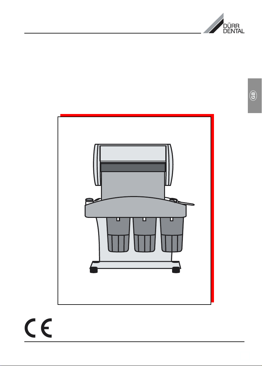
INSTALLATION AND OPERATING INSTRUCTIONS
X-RAY FILM PROCESSOR DÜRR XR 04
Page 2

2
Page 3
CONTENTS
Important information
1. Notes......................................................... 4
1.1 Test of conformity .............................. 4
1.2 General Notes.................................... 4
1.3 General Safety Notes ........................ 4
1.4 Notes concerning Medical Appliances
5
1.5 Electrical Safety Notes ...................... 5
1.6 Warnings and Symbols .....................5
2. Product information ................................ 6
2.1 Use in accordance
with regulations.................................. 6
2.2 Use not in accordance
with regulations.................................. 6
3. Model survey ........................................... 6
4. Delivery schedule .................................... 6
4.2 Special extras .................................... 6
5. Technical data.......................................... 6
7. Function description ...............................7
6. Function principle ................................... 7
Installation
8. Installation
Requirements .......................................... 8
8.1 Installation site ................................... 8
8.2 Installation possibilities of the
Processor........................................... 8
Gebrauch
9. Changing chemicals
and water .................................................. 9
9.1 Taking off daylight attachment........... 9
9.2 Cleaning film transport .................... 10
9.3 Removing heater .............................11
9.4 Disposing of used chemicals .......... 11
9.5 Mixing new chemicals ..................... 11
9.6 Assembling of the XR 04 ................. 12
10. Operation ...............................................12
11. Replacing film transport cogs ............. 13
12. Wiring diagram ...................................... 14
Disposal
13. Disposing of Appliance ......................... 14
3
Page 4

IMPORTANT INFORMATION
1. NOTES
1.1 Test of conformity
This product was tested for conformity to the
Guidelines 93/42/EWG of the European Union
and has been found to satisfy all criteria of
these guidelines.
1.2 General Notes
• These Installation and Operating Instructions
form an integral part of the unit. They must
be kept close to the unit at all times. Precise
observance of these instructions is a precondition for use of the unit for the intended
purpose and for its correct operation. New
personnel must be made aware of the
contents, and they should be passed on to
future operating staff.
• Safety for the operator as well as troublefree operation of the unit are only ensured if
use is made of original equipment parts.
Moreover, use may only be made of those
accessories that are specified in the
technical documentation or that have been
expressly approved and released by Dürr
Dental for the intended purpose.
• Dürr Dental cannot guarantee for the safety
or proper functioning of this unit in the case
where parts or accessories are used which
are not supplied by Dürr Dental.
• Dürr Dental are only responsible for the
equipment with regard to safety, reliability
and proper functioning where assembly,
resettings, changes or modifications,
extensions and repairs have been carried
out by Dürr Dental or an agency authorized
by Dürr Dental and if the equipment is used
in conformity with the Installation and
Operating Instructions.
• These Installation and Operating Instructions
conform to the relevant version of the
equipment and the underlying safety
standards valid at the time of going to press.
All switches, processes, trade marks,
software programs and appliances named in
this document are registered names.
• Any reprinting of the technical
documentation, in whole or in part, is subject
to prior approval of Dürr Dental being given
in writing.
1.3 General Safety Notes
This appliance has been designed and
constructed by Dürr Dental so that correct
usage of the appliance is virtually free of any
possible injury or danger. In spite of this, we
feel it is our duty to mention the following
safety measures in order to prevent any
possible danger.
• When using this appliance all local and
relevant regulations must be observed!
Converting or modifying the appliance in
any way is strictly prohibited. In such cases,
any and all guarantees immediately become
invalid. The operation of modified
appliances can be punishable by law. In the
interests of trouble-free operation the
operator is responsible for observing these
regulations.
• Retain the packaging for possible return of
the product to the manufacturers. Ensure
that the packaging is kept out of the reach of
children. Only the original packaging
provides adequate protection during
transport of the unit.
Should return of the product to the
manufacturers be necessary during the
guarantee period, Dürr Dental accepts no
responsibility for damage occurring during
transport where the original packaging was
not used!
• Before every use the operator must check
the functional safety and the condition of the
appliance.
• The operator must be knowledgeable in the
operation of the appliance.
• The product is not designed to be used in
medical treatment areas where there exists
the danger of explosion. Areas where
explosions could occur are those where
flammable anesthetic material, skin
cleansers, oxygen and skin disinfectants are
present. This appliance is not to be used in
areas where the atmosphere could cause
fire.
4
Page 5
1.4 Notes concerning Medical Appliances
• This product is a technical medical
appliance and, as such, may only be
operated by trained personnel, or persons
who, as a result of specialist knowledge, are
familiar with this type of appliance.
• Do not lie multi-socket units on the floor.
• Other systems should not be plugged into
the same multi-socket unit.
1.5 Electrical Safety Notes
• The appliance may only be connected to an
earthed safety socket.
• Before connecting the appliance to the
power supply check that the electrical
current and the frequency of the device as
described on the appliance are compatible
with that of the power supply.
• Check the appliance and the power supply
cables for possible damage before
switching on. Damaged cables, plugs and
sockets must be replaced before use.
• Never touch open supply outlets and
patients simultaneously.
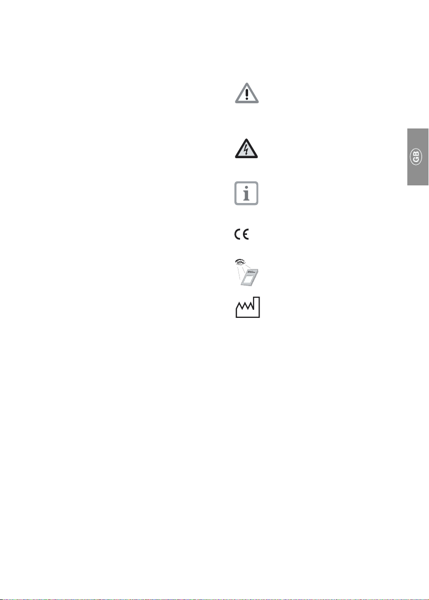
1.6 Warnings and Symbols
In the Installation and Operating Instructions
use is made of the following terms or symbols
to denote information of special importance:
Information and/or mandatory
regulations or prohibitions for the
prevention of personal injury or
substantial property damage
Warning of dangerous electrical
voltage.
Special information regarding the
economical use of the equipment and
other information
CE-Labeling without Notified Body
Number
Observe Installation and Operating
Instructions!
Date of manufacture
5
Page 6

2. PRODUCT INFORMATION
4. DELIVERY SCHEDULE
2.1 Use in accordance with regulations
The Dürr XR 04 X-ray developing machine is
to be used exclusively for the automatic
development of intra-oral X-ray films.
Use in accordance with the regulations
includes compliance with the instructions for
mounting and usage as well as compliance
with the provisions on setting up, installing and
operating the machine, and on warranty.
Use in accordance with the regulations also
includes compliance with all legal provisions
in force in the place where the machine is
being used, with regard to work safety and the
disposal of chemicals.
2.2 Use not in accordance with regulations
If the machine is used for a purpose other than
the one stated in the regulations, the
manufacturer shall not be legally liable for any
damage arising as a result of same. In such
cases, the user shall incur the risk.
3. MODEL SURVEY
X-ray film Processor XR 04
Model:Model:
Model: 1740-01 (230 V)
Model:Model:
1740-02 (110 V )
1740-03 (230 V) with heater
1740-04 (110 V) with heater
4.1 Optional extras
1 X-ray film
Processor XR 04 ............................. 1740-01
1740-02
1740-03
1740-04
1 Securing set ........................... 1740-004-00
1 Chemical set...................... 1307-080-00/40
1 Guarantee card ...................... 9000-464-86
1 Instruction manual ............. 9000-600-05/01
1 Wall mounting ......................... 1740-011-00
4.2 Special extras
1 Heater, PC-board 110V ......... 1740-994+00
1 Heater, PC-board 230V ......... 1740-993+00
1 Table trestle ............................ 1740-012-00
5. TECHNICAL DATA
Model 1740 - 01 02 03 04
Voltage (V) 230 110 230 110
Current
Consumption
(mA) 35 - 400 -
Heater w/o w/o with with
Frequency (Hz) ................................... 50 - 60
Film run through time (adjustable min) 2 - 6
Total output (W) .......................................... 85
Heat output (W)........................................... 40
Protection rating Il, Protection type IP 21
Heating up time
(approx. min) (8 min / °C) ................... 20 - 30
Weight (kg) without chemicals ................ 7,5
6
Page 7

6. FUNCTION PRINCIPLE
3
45
2
1
7. FUNCTION DESCRIPTION
Switch on main switch (2).
Heater for Developer/Fixer baths is started
(8 min/°C to 25°C bath temperature).
Switch on regulator (1) for the film
transport and set the processing time
(2-6 min.).
The films are carried via the film transporter
through the Developer-/Fixer baths. The
processed film remains in the perforated
collector and should be taken out after
approx. 5 mins.
6
E Developer bath
F Fixer bath
W Water bath
1 Processing time regulator
2 Unit switch ON/OFF
3 Film transporter
4 Heater
5 Transporter drive
6 Perforated collector
7
Page 8

INSTALLATION
8. INSTALLATION REQUIREMENTS
10
8.1 Installation site
• The Processor XR 04 must be assembled in a
dry, well ventilated room.
Never expose the Processor to direct
sunlight!
With too strong sunlight pre-exposure of
films and overheating of chemicals can
1
11
2
12
occur.
8.2 Installation possibilities of the
Processor
To obtain perfect development results, the
installation area must be stable, flat and level.
• Assemble at or bring up to working height.
• Near a sink.
• Near a mains socket.
At a distance of approx.1.5 m from the
installation site of the XR 04, there should be a
mains socket for the power cable of the XR 04.
The mains socket should be sited so that the
power plug of the machine is easily visible
and accessible without danger.
(DIN 15990, para. 3.3.2 and 3.4)
For safety technical reasons the
power connection should only be
made shortly before putting the
machine into operation.
Wall mounting see. pict. 1.
• Mark the position for drilling the holes for the
XR 04 (10) on the wall.
• Drill the holes, insert wall plugs and fit screws.
• Hang XR 04 on the screws, adjust as
necessary, then tighten screws.
Table mounting see pict. 2.
Fit the upper part of the XR 04 onto the edge
of the table and fasten it (11).
Table installation see pict. 3.
For this assembly it is necessary to have a
separate table trestle (12), (not included in the
delivery schedule)
Order no.1740-012-00.
3
8
Page 9

13
14
GEBRAUCH
9. CHANGING CHEMICALS AND WATER
Before working on opened
equipment, pull out the mains plug.
• Change chemicals after approx. 200 films or
after 3 weeks at the latest.
• Change water twice a week.
The information for changing the
4
3
chemicals refer only when using
"DÜRR Chemicals"."DÜRR Chemicals".
"DÜRR Chemicals".
"DÜRR Chemicals"."DÜRR Chemicals".
In Germany, as well as some other
countries, used x-ray chemicals are
classified as special waste and must
be collected separately and disposed
of.
9.1 Taking off daylight attachment
Before taking off the daylight
attachment: Pull out mains plug.
Push frame support (14) inwards with both
thumbs. Swing daylight attachment (13)
upwards and remove, see pict. 4.
5
9
Page 10

6
7
7a
9.2 Cleaning film transport
16
• Lift the film transport (3, Fig. 5) upwards to
remove and rinse with warm water at
approx. 40°C.
• If the film transport is very dirty it can be
separated into two pieces and cleaned.
Hereby :
• Pull the 4 snap fasteners of the film transport
(16) out until they click into place.
• Using even pressure pull the top half from
the bottom half (Fig. 6).
• Rinse both halves and, if necessary, clean
with a brush.
17
18
19
20
21
Please note that when cleaning the
open film transport the toothed belt
can get out of position. Therefore,
before reassembling the film transport
check the position of the cogs (19)
and the toothed belt (20) as follows:
• The transport arm (17) should be
clockwise (21) clockwise (21)
clockwise (21) until it aligns with marking
clockwise (21) clockwise (21)
(A).
• The film carrier (18) should now be aligned
with marking (B). If not, then correct the
position of the toothed belt (20):
• Fig. 7a: Hold the film transport, so that the
large, white cogs cannot turn.
Fig. 7b: Lift the toothed belt (20) from the
cogs (19), align the film carrier (18) with
marking (B).
Replace the toothed belt in the correct
position and press onto the teeth of the cog
wheel.
Here by take care that the toothed belt
sits correctly on the cog with no
overlap, otherwise there is the danger
that the belt comes loose from the
cogs during operation.
• Place the two halves of the film transport
against each other and replace the snap
fasteners.
turnedturned
turned
turnedturned
10
18
19
20
7b
Page 11

9.3 Removing heater
Only necessary with table-top model,
otherwise the Developer-/Fixer
containers cannot be removed.
Lift up Heater (4) and hang on frame.
9.4 Disposing of used chemicals
W
F
E
8
• Remove by rotating the 3 containers
Developer (E)/Fixer (F)/Water (W) and very
carefully take off downwards.
• Empty out chemical and water containers.
• Dispose of chemicals.
• Rince containers with warm water and clean
thoroughly.
9.5 Mixing new chemicals
Fill containers only up to the
markings.
Danger of "spillage" during
insertion of containers.
• Pour developer up to black marking in
container (E) and then fill up with fresh water
to the upper marking. Insert container and
rotate to fasten.
• Pour fixer up to the red marking in container
(F) and then fill up with fresh water to the
upper marking.
Insert container and rotate to fasten.
• Fill container (W) with white markings up to
the upper mark with fresh water.
9
Insert container and rotate to fasten.
11
Page 12

10
9.6 Assembling of the XR 04
• Replace heater (4) and film transporter (3),
4
see pict. 5.
13
• Replace daylight attachment (13).
• Put the perforated collector (6) in the water
container (6), see pict. 11 and right fold-in
6
page.
FWE
12
11
12
Pos. 1
Pos. 2
10. OPERATION
• Machine switch (2) ON.
Developer-/Fixer bath are being warmed up.
• Processor regulating timer (1) ON.
Set processing time, see pict. 12.
without heater:
Regulator on pos. 1
3 1/2 mins
with heater:
Regulator on pos. 2
2 1/2 mins.
• Place the wrapped exposed film in the
daylight attachment.
• Insert hands into rubber cuffs and unwrap
film.
• Enter film into the transporter system.
• Remove processed film from the water bath.
Washing: A min. of 5 mins in the perforated
collector (6) (max. 1 hour)
• Processor regulating timer (1) OFF.
Page 13

11. REPLACING FILM TRANSPORT COGS
• Remove the locking ring of the defective cog
and pull the cog from the roller.
• Align the transport arm (A) with marking (B),
press new cog into position and secure with
the locking ring.
• Place the toothed belt cog (X) onto the film
carrier roller (C) so that this appears as a D .
The transport arms (A) must be aligned with
the markings (B) and the film carrier (C)
shows a D shape.
• Place the toothed belt in position and
synchronise, see Point 9.2.
X
C
B
A
B
A
13
Page 14

12. WIRING DIAGRAM
30 31 32
X3
NTC
X2
43
2
1
X2
N
X1
L
X1
36 35 34 33
X3
X4
30 Mains
31 Heater
32 Processing time regulator
33 Drive motor
34 PC board
35 Unit switch
36 Fuse 100 mA T
14
DISPOSAL
13. DISPOSING OF APPLIANCE
The built-in electronic plate and components
must be disposed of in the same way as
electronic scrap metal.
The remaining structural components can be
disposed in accordance with the relevant local
regulations.
 Loading...