

Page 1
Installation and operating instructions
2008/04
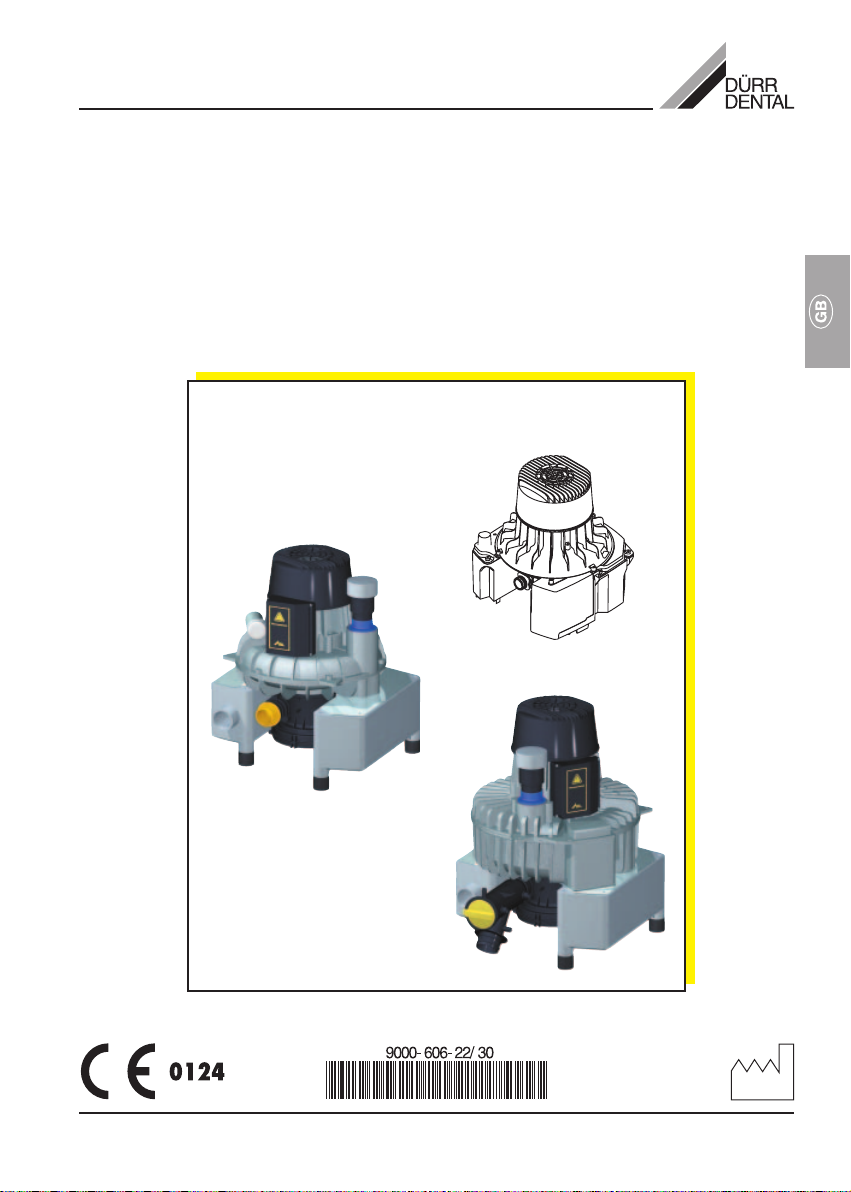
VS 300 S / VS 600 / VS 900
combi-suction unit
Page 2

2
Page 3
Contents
Important Information
1. Notes......................................................... 4
1.1 Test of conformity .............................. 4
1.2 General Notes.................................... 4
1.3 General Safety Notes ........................ 4
1.4 Notes concerning
Medical Appliances ...........................5
1.5 Using Peripheral Devices ..................5
1.6 Safety notes concerning electric
current................................................ 5
1.7 Warnings and Symbols .....................5
2. Product information ................................ 6
2.1 Correct Usage ................................... 6
2.2 Incorrect Usage ................................. 6
2.3 Product Description........................... 6
3. Delivery Contents .................................... 6
3.1 Suction unit VS 300 S ........................6
3.2 Suction Unit VS 600 ........................... 7
3.3 Suction Unit VS 900 ........................... 7
4. Technical Data........................................... 8
4.1 Suction Unit VS 300 ........................... 8
4.2 Suction Unit VS 600 ........................... 9
4.3 Suction Unit VS 900 ......................... 10
4.4 Environmental conditions ................ 11
5. Functional description ..........................11
6. Functional description ..........................12
Installation
8. Connections........................................... 15
8.1 VS 300 connections......................... 15
8.2 VS 600 connections......................... 16
8.3 VS 900 connections......................... 17
9. Electrical Connections .........................18
9.1 Connection requirements ................18
9.2 Control unit (VS 600 + VS 900) ......18
9.3 Motor terminal box connections
(VS 600 + VS 900 ............................18
9.4 Connection of VS 300 S to
Control Unit ......................................19
10. Commissioning ..................................... 19
Care
11. Cleaning and Disinfection of the
Suction Unit ........................................... 20
12. Maintenance...........................................20
Disposal
13. Appliance disposal................................ 20
7. Set-up ..................................................... 13
7.1 Set-up location .................................13
7.2 Alternative set-ups........................... 13
7.3 Securing the suction unit ................. 13
7.4 Fitting a pressure
compensation hose ......................... 13
7.5 Rinsing Unit .....................................13
7.6 Plumbing materials .......................... 14
7.7 Hose materials .................................14
7.8 Laying hoses and pipes .................. 14
Trouble-shooting
14. Tips for Technicians .............................. 21
3
Page 4

Important Information
1. Notes
1.1 Test of conformity
This product was tested for conformity to the
Guidelines 93/42/EWG of the European Union
and has been found to satisfy all criteria of
these guidelines.
1.2 General Notes
• These Installation and Operating Instructions
form an integral part of the unit. They must
be kept close to the unit at all times. Precise
observance of these instructions is a precondition for use of the unit for the intended
purpose and for its correct operation. New
personnel must be made aware of the
contents, and they should be passed on to
future operating staff.
• Safety for the operator as well as troublefree operation of the unit are only ensured if
use is made of original equipment parts.
Moreover, use may only be made of those
accessories that are specified in the
technical documentation or that have been
expressly approved and released by Dürr
Dental for the intended purpose.
• Dürr Dental cannot guarantee for the safety
or proper functioning of this unit in the case
where parts or accessories are used which
are not supplied by Dürr Dental.
• Dürr Dental are only responsible for the
equipment with regard to safety, reliability
and proper functioning where assembly,
resettings, changes or modifications,
extensions and repairs have been carried
out by Dürr Dental or an agency authorized
by Dürr Dental and if the equipment is used
in conformity with the Installation and
Operating Instructions.
• These Installation and Operating
Instructions conform to the relevant version
of the equipment and the underlying safety
standards valid at the time of going to press.
All switches, processes, trade marks,
software programs and appliances named in
this document are registered names.
• Any reprinting of the technical
documentation, in whole or in part, is subject
to prior approval of Dürr Dental being given
in writing.
1.3 General Safety Notes
This appliance has been designed and
constructed by Dürr Dental so that correct
usage of the appliance is virtually free of any
possible injury or danger. In spite of this, we
feel it is our duty to mention the following
safety measures in order to prevent any
possible danger.
• When using this appliance all local and
relevant regulations must be observed!
Converting or modifying the appliance in
any way is strictly prohibited. In such cases,
any and all guarantees immediately become
invalid. The operation of modified
appliances can be punishable by law. In the
interests of trouble-free operation the
operator is responsible for observing these
regulations.
• Retain the packaging for possible return of
the product to the manufacturers. Ensure
that the packaging is kept out of the reach of
children. Only the original packaging
provides adequate protection during
transport of the unit.
Should return of the product to the
manufacturers be necessary during the
guarantee period, Dürr Dental accepts no
responsibility for damage occurring during
transport where the original packaging was
not used!
• Before every use the operator must check
the functional safety and the condition of the
appliance.
• The operator must be knowledgeable in the
operation of the appliance.
• The product is not designed to be used in
medical treatment areas where there exists
the danger of explosion. Areas where
explosions could occur are those where
flammable anesthetic material, skin
cleansers, oxygen and skin disinfectants are
present. This appliance is not to be used in
areas where the atmosphere could cause
fire.
4
Page 5
1.4 Notes concerning Medical Appliances
• This product is a medical technical
appliance and may only be used by those
persons whose training and/or experience
guarantees correct usage.
1.5 Using Peripheral Devices
• Units may only be connected to the system
or to other units when it has been
established that there is no reduction of
safety for the patient, the operator or the
environment through such connection.
Where it is not absolutely clear from the
documentation whether safety is reduced by
such connection, then the operator must
establish, e.g. by contacting either the
manufacturer or an expert, that there is no
reduction of safety for the patient, the
operator or the environment through such
connection.
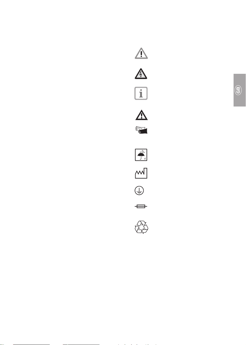
1.7 Warnings and Symbols
The operating and installation instructions
contain the following labeling and symbols for
especially important information.
Restrictions and regulations
concerning the prevention of injury
or damage.
Warning concerning dangerous
electrical voltage.
Special instructions concerning
economic use of the appliance or
other notes.
Obseve notes in supplementary
documentation
For added safety of operators
protective gloves should be worn
while working on the Suction Units.
1.6 Safety notes concerning electric current
• This unit may only be connected to a
standard approved earthed electrical socket
(VS 600 + VS 900).
• Before connecting the appliance to the
mains, check that the frequency and
voltages given for the appliance match
those of the available power supply.
• Before commissioning the appliance all
connections must be checked for possible
damage. Damaged connections, plugs and
sockets should be replaced immediately.
• Never touch patients and open sockets of
the appliance simultaneously.
• All relevant electrical rules and regulations
must be observed during installation and
when carrying out any repairs or
maintenance on the appliance.
Take environmental influences into
consideration.
Date of manufacture.
Ground connection.
Fuse.
Recycling
~ Single phase AC current.
3~ Three-phase AC current.
3N~ Three-phase AC current with central
conductor.
5
Page 6

2. Product information
3. Delivery Contents
2.1 Correct Usage
The suction unit has been designed to
produce a vacuum in order to suck up saliva,
rinsing water and other fluids which occur
during dental treatment and which are
transported to the waste water system.
Installation in medical facilities:
As far as was possible, all requirements
concerning Medical Products have been taken
into consideration in the design and
production of these appliances. Thus, the
appliance may be installed in any facility
providing medical treatment.
Where the appliance is set up in a medical
clinic or other facility, then the requirements
demanded under directive 93/42 EWG as well
as all relevant standards must be observed on
installation.
2.2 Incorrect Usage
Any usage above and beyond that explicitly
laid down in the operating instructions is
deemed to be incorrect usage. The
manufacturer accepts no liability for damage
or injury resulting from incorrect use. All risk is
carried by the operator.
2.3 Product Description
The combi-suction unit is a suction unit with an
integrated separation unit. Separation within
the treatment station (e.g. chair) is no longer
necessary.
The suction unit separates the fluids and solid
particles sucked up during treatment from the
air using a two-step separation system of
cyclone separator and separation turbine.
The separation turbine is especially effective
at preventing fluids and blood foam from
being sucked into the turbine section of the
suction unit.
The fluids sucked up are continually being
rotated at high speed and transported to the
waste system; thus, there is no interruption of
suction due to the system being too full.
The suction system is mounted on rubber
mountings, which reduce vibration and
operating noise.
The items listed under Special
Accessories are not included in the
standard delivery contents, but can be
ordered specially.
3.1 Suction unit VS 300 S
3.1.1 Contents
Model 7122-01/002
Typ 230 V, 1~, 50 Hz
with control unit
Model 7122-02/002
Typ 230 V, 1~, 60 Hz
with control unit
Model 7122-05/003
Typ 100 V, 1~, 50 - 60 Hz
with control unit
3.1.2 Accessories
Connector set ............................... 7122-001-00
Suction hose LW 30, grey ............ 9000-317-27
Hose LW 20 .................................. 9000-317-22
Hose LW 30, Aluminium ............... 9000-317-37
OroCup (not Japan) ..................... 0780-350-00
3.1.3 Special Accessories
Wall mounting ............................... 7130-190-00
Housing ........................................ 7122-200-00
Exhaust bacterial filter with
accessories .................................. 7120-143-00
Rinsing unit ................................... 7100-250-50
6
Page 7

3.2 Suction Unit VS 600
3.2.1 Contents
Model 7128-01/002
Type 230 V, 1~, 50 Hz
with control unit
3.3 Suction Unit VS 900
3.3.1 Contents
Model 7133-01/001
Type 230 V, 1~, 50 Hz
without control unit
Model 7128-02/002
Type 400 V, 3~, 50–60 Hz
with control unit
Model 7128-02/003
Type 230 V, 3~, 50-60 Hz
with control unit
Model 7128-05/003
Type 200 V, 3~, 50-60 Hz
with control unit
3.2.2 Accessories
Control unit
for type 7128-01/002 .................... 0700-500-50
for type 7128-02/002 .................... 0732-100-56
for type 7128-02/003 .................... 0732-100-57
for type 7128-05/003 .................... 0732-100-57
Pipe connector set ....................... 7128-001-00
Hose LW 40 .................................. 9000-318-70
Hose LW 50.. ........................ 9000-317-002
Hose LW 20 .................................. 9000-317-22
OroCup ......................................... 0780-350-00
3.2.3 Special accessories
Noise reducing cover................... 7128-991-00
Pressure compensation hose ...... 7112-101-00
Wall mounting ............................... 7130-190-00
Floor installation console ............. 7130-191-00
Bacterial exhaust filter ................. 0732-001-00
Fixing plate for exhaust filter ....... 0732-000-06
Noise reducer for exhaust ........... 0730-991-00
Rinsing Unit .................................. 7100-250-50
Model 7133-02/001
Type 400 V, 3~, 50 Hz
without control unit
Model 7133-01/002
Type 230 V, 1~, 50 Hz
with control unit
Model 7133-02/002
Type 400 V, 3~, 50 Hz
with control unit
Model 7133-03/002
Type 230 V, 3~, 50 Hz
with control unit
Model 7133-05/002
Type
200 V, 3~, 50-60 Hz
230 V, 3~, 60 Hz
with control unit
3.3.2 Accessories
Control unit
for type 7133-01/002 .................... 0732-100-55
for type 7133-02/002 .................... 0732-100-56
for type 7133-03/002 .................... 0732-100-57
for type 7133-05/002 .................... 0732-100-59
Pipe connector set ....................... 7133-001-00
Hose LW 20 .................................. 9000-317-22
Hose LW 50 (0.6m) .................... 9000-317-001
Hose LW 50 (1.5m) .................... 9000-317-002
OroCup ......................................... 0780-350-00
3.3.3 Special accessories
Noise reducing cover................... 7128-991-00
Pressure compensation hose ...... 7130-991-00
Wall mounting ............................... 7130-190-00
Floor installation console ............. 7130-191-00
Bacterial exhaust filter ................. 0732-001-00
Fixing plate for exhaust filter........ 0732-000-06
Noise reducer for exhaust ........... 0730-991-00
Rinsing unit ................................... 7100-250-50
7
Page 8

4. Technical Data
4.1 Suction Unit VS 300 S
Model 7122 -01 -02 -05
Voltage V 230 230 100
Supply frequency Hz 50 60 50 - 60
Phases 111
Rated current A 2.9 3.7 8,0 - 10
Residual current A 8.2 9.1 21 - 20,5
Motor protection switch A Motor winding overheat protector 160°C (±5°C)
Power consumption W 580 800 650 - 850
R.P.M. min
Max. flow volume l/min 4
Air flow l/min see Fig. 3
Max. No. treatment stations 1
Weight kg 12,5
Dimensions see Fig. 2
Noise level* dB(A), ±1.5 63 - 64
Duty cycle % 100
Protection type IP 24
Protection class I
Vacuum connection DürrConnect Spezial (hose ø 30 mm (inner))
Exhaust air connection DürrConnect Spezial (Aluminium hose ø 30 mm (inner))
Waste water connection DürrConnect System (hose 20 mm (inner))
Auxiliary air vent setting mbar –
Protective low voltageProtective low voltage
Protective low voltage V 24 ~
Protective low voltageProtective low voltage
Power outputPower output
Power output VA 4
Power outputPower output
-1
2750 3100 2810 - 3220
* According to EN ISO 1680 air noise emissions; measured in soundproof room.
Higher values will be achieved in reverberant rooms.
23
8
Page 9

4.2 Suction Unit VS 600
Model 7128 -01 -02 -05
Voltage V 230 400 230 200
Supply frequency Hz 50 50 - 60 50 - 60 50 - 60
Phases 133 3
Rated current A 5,0 1.8 - 2.3 3.1 - 4.1 3.2 - 4.0
Residual current A22 89 31
Motor protection switch A – 2.5 - 4.0 3.5 - 4.5 4
Power consumption W 1100 1000 1420 1420
R.P.M. min
Max. flow volume l/min 10
Air flow l/min see Fig. 5
Max. No. treatment stations 3
Weight kg 25
Dimensions see Fig. 4
Noise level* dB(A), ±1.5 63
Duty cycle %ED 100
Protection type IP 44
Protection class I
Vacuum connection ø 40 mm (outer) (DN 40)
Exhaust air connection ø 50 mm (outer)
Waste water connection DürrConnect System
Auxiliary air vent setting mbar 170 (170 hPa)
-1
2850 2850/3300
* According to EN ISO 1680 air noise emissions; measured in soundproof room.
Higher values will be achieved in reverberant rooms.
4 5
9
Page 10

4.3 Suction Unit VS 900
Model 7133 -01 -02 -03 -05
Voltage V 230 400/230 230 200 230
Supply frequency Hz 50 50 50 50-60 60
Phases 13333
Rated current A 6.5 2.5/4.0 4.0 5.7-6.7 6.7
Residual current A 29 14/24 24 33 34
Motor protection switch A 7.5 2.7/4.6 4.5 6,0-7,0 7,0
Power consumption W 1480 1520 1420 1500-2080 2130
R.P.M. min
Max. fluid flow l/min 16
Air flow l/min see Fig. 7
Max. No. treatment stations 5
Weight kg 35
Dimensions see Fig. 6
Noise level* dB(A), ±1.5 64
Duty cycle % 100
Protection type IP 44
Protection class I
Vacuum connection ø 47 mm (outer)
Exhaust air connection ø 50 mm (outer)
Waste water connection DürrConnect System
Auxiliary air vent setting mbar 170 (17 hPa)
-1
2770 2820 2820 2810-3200 3310
* According to EN ISO 1680 air noise emissions; measured in soundproof room.
Higher values will be achieved in reverberant rooms..
76
10
Page 11

4.4 Environmental conditions
Take environmental influences into
account. The appliance must not be
used in damp or wet locations.
Storage and transport
Temperature: ......................... –10 °C to +60 °C
Rel. humidity: .................................... max. 95%
Operation
Temperature: ........................ +10 °C to +40 °C
Rel. humidity: .................................... max. 70%
5. Functional description
VS 900 as example of principle function
In the suction unit the fluids and solid particles
which are sucked up are separated from air
using a two-step separation system This
separation system consists of a cyclone
separator and a separation turbine.
The suction process runs continuously. The
intake mixture of fluid, solid particles and air
enters the suction unit via the intake
connection (D). The coarse filter (B) retains the
larger solid particles. The remaining mixture
proceeds to the cyclone separator (I) and is
then rotated in a spiral action. In this 1st stage
the fluids and any remaining solid particles are
thrown against the outer walls of the cyclone
separator by the centrifugal action. Initially
there is only a "coarse separation“ of the
fluids.
In the following 2nd stage the separation
turbine (J) sets a "fine separation“ into play, in
which the remaining fluids are now separated
from the air which has transported them thus
far.
The waste water pump (H) now transports the
fluids from the centrifuge together with the fine
solid particles to the waste water connection
(E) and the central waste water system.
The air, now free of any fluids, is transported
to the exhaust air system (C) using the
vacuum provided by the action of the turbine
wheel (K).
The turbinen wheel and the waste water pump
are driven by the motor (L).
In order to separate dental amalgam it
is necessary to install an amalgam
separator, e.g. model 7801-07, after
the waste connection (E).
Should an amalgam separator from
another manufacturer be fitted, then
the max. fluid flow rate of the
suction unit must be taken into
account.
11
Page 12

6. Functional description
A
B
L
K
J
I
H
C
D
A Auxiliary air vent
B Coarse filter
C Exhaust air connection
D Intake sleeve
E Waste water connection
F Diaphragm valve
12
G
F
E
G Exhaust air noise reducer
H Waste water pump
I Cyclone separator
J Separation turbine
K Turbine wheel
L Motor
Page 13

Installation
7. Set-up
7.1 Set-up location
• The ambient room temperature must not fall
below 10 °C and should not be allowed to
rise above 40 °C. The relative humidity must
not exceed 70%.
• Installation in a purpose-built room, e.g. in
boiler room, must be approved before-hand
(i.e. observe local regulations).
• Installation in wet rooms is not permissible.
• When installing this unit inside a cabinet or
in a machinen room, sufficient air inlet and
outlet openings must be provided; these
must have a minimum of 120 cm² crosssection.
If insufficient ventilation is available then a
fan must be fitted, this must be able to
provide at least 2 m3/min ventilation flow;
additionally, an inlet opening must be
provided for cool air.
7.2 Alternative set-ups
• On the same floor as the surgery.
• In a ventilated cabinet (e. g. Dürr PTS 105/
195).
• In Dürr-housing (VS 300 S only)
as extension to the treatment unit and
connected to electrical floor connection.
• On a lower floor than the surgery.
VS 300 S
When installing the VS 300 S in a cellar or
similar room, then the unit should be mounted
on a platform or on the wall at a height of 30
cm above the floor.
7.3 Securing the suction unit
• When setting up the suction unit together
with an amalgam separator a floor console
should be included.
The suction unit must be at least
20 cm above any amalgam separator
which is also installed.
• For mounting on the wall we recommend
using the Dürr wall-mounting unit.
Information concerning fitting can be
found in the installation instructions
which are supplied with the floor
console or the wall-mounting unit.
7.4 Fitting a pressure compensation
hose
• For suction units VS 600 and VS 900 the
installation of a pressure compensation hose
is necessary where an amalgam separator is
present.
Due to the high rate of fluid flow
through these units, a pressure
compensation hose is required
between the suction unit and amalgam
separator and serves as intermediate
storage in cases of spontaneous rush
of water.
Information on installation can be
found in the instructions supplied with
the pressure compensation hose.
7.5 Rinsing Unit
It is strongly recommended that a rinsing unit
be added to the suction unit for surgical
treatment. This enables a small amount of
water to be fed into the system during suction
which serves to dilute the secretions and allow
them to be transported through the system
more easily.
This rinsing unit should either be integrated
into the treatment station itself or can be set
up in the vicinity of the suction unit.
13
Page 14

7.6 Plumbing materials
Only the following pipe materials may be
used:
Vacuum-sealed HT-drain pipe made from
polypropylene (PP), chlorinated polyvinylchloride (PVC-C), unplasticized polyvinylchloride (PVC-U) or polyethylene (PEh).
Do not use:
Acrylonitrile-Butadiene-Styrene
(ABS) or Styrene-Copolymer blends
(e.g. SAN+PVC).
7.7 Hose materials
For waste water and suction connections use
only PVC flexible spiral hoses with integrated
spiral or hoses of equivalent type.
Do not use:
Hoses which are not resistant to
dental disinfectants and other
chemicals, or rubber or PVC hoses
with insufficient flexibility.
7.8 Laying hoses and pipes
Waste water connections should be
completed in accordance with the local
regulations.
The connection between supply and
the suction unit itself should be kept as
short as possible, be straight without
bends and carried out with the flexible
hose supplied. This will avoid any
vibration being effected in the
plumbing system.
14
Page 15

8. Connections
The connections illustrated here are
only meant as examples which can be
varied according to the conditions
present in the individual surgery.
8.1 VS 300 connections
1 Connector 30/36
1a O-Ring
2 Hose clip ø30mm
3 Exhaust hose (Aluminium) inner ø30mm
4 Angle piece DN 30
5 O-Ring 30x2
6 Securing ring
7 Plug, external ø36mm
8 O-Ring 20x2.0
9 Securing ring
10 Hose socket ø25mm
11 Hose clamp ø28mm
12 Suction hose, internal ø30mm
13 Double plug
14 Waste water hose, internal ø20mm
15
Page 16

8.2 VS 600 connections
5 O-Ring 30x2
7 Plug, external ø36mm
8 O-Ring 20x2,0
9 Securing ring
10 Hose socket ø20mm
11 Hose clamp ø28mm
13 Double plug
14 Waste water hose, internal ø20mm
20 Elbow DN50
21 Hose clamp ø55mm
22 Exhaust air hose, internal ø50mm
23 Hose plug DN40/50
24 Hose clamp ø46mm
25 Suction hose ø40mm
16
Page 17

8.3 VS 900 connections
5 O-Ring 30x2
7 Plug, external ø36mm
8 O-Ring 20x2.0
9 Securing ring
10 Hose socket ø20mm
11 Hose clamp ø28mm
13 Double plug
14 Waste water hose, internal ø20mm
20 Elbow DN50
21 Hose clamp ø55mm
22 Exhaust air hose, internal ø50mm
30 Snap-lock connector, straight
31 Snap-lock connector, bent
32 Collar seal
33 Union nut
34 Suction hose, internal ø55
17
Page 18

9. Electrical Connections
The electrical supply unit must conform to all
national rules and regulations concerning
power supply to surgeries and clinics.
Where electrical connection to the mains is via
floor or ceiling an all-polar isolating device (allpolar switch or all-polar power safety switch
(fused)) with > 3mm contact opening width
must be built into the system.
Fusing: LS-Switch 16 A, Characteristics B, C
and D according to EN 60898
Electrical connection to the main
power supply using a shockproof
plug or CCE-type plug is not
permitted
9.1 Connection requirements
100–110 V / 230 V / 400 V cables
(permanently fitted mains supply):
• NYM-J 3 x 1.5 mm² / 5 x 1.5 mm²
100–110 V / 230 V / 400 V cables (mains
supply, flexible):
The connection between control unit and
suction unit or between mains supply socket
and suction unit should be of PVC-sleeved
cable:
H05 VV-F 5G1.5 mm² / 5G1.5 mm²
or rubber-sleeved:
H05 RN-F 3G1.5 mm² / 5G1.5 mm²,
H05 RR-F 3G1.5 mm² / 5G1.5 mm²
A cable of cross-section 1 mm² may be usde
when installing the VS 300 S.
24 V Control line for VS 300 S
Flexible cable connection: PVC-Data cable
LiYY 3 x 0.5 mm²
Order-No. 9000-118-83
9.2 Control unit (VS 600 + VS 900)
The suction unit can be connected to a control
unit which is either included in the contents or,
if not, may be ordered as a special accessory.
The connection plans and circuit diagrams are
included in the control unit installation and
operating instructions.
24 V control connection, VS 600 + VS 900
Protective low voltage for:
• Hose holder (manifold)
• Station selector switch
• Spittoon valve
Permanent connection: (N)YM (St)-J 4x1.5
mm² sheathed shielded cable.
Flexible connection: PVC-Data cable
LiYCY 4x1.0 mm², sheathed shielded cable as
used in telecommunications and EDP or lightPVC-control sheathed shielded cable.
18
Page 19

12
9.3 Motor terminal box connections
(VS 600 + VS 900
The power supply from the control unit are
connected to the appropriate contact points in
the motor terminal box. Connection plans and
the relevant circuit diagrams can be found in
the Installation and Operating Instructions of
the Control Unit.
Suction Units VS 600 and VS 900
• 1/N/PE AC 230 V
• 3/N/PE AC 230 V, 3/N/PE AC 400 V
For details concerning the contact bar in the
motor terminal box of the suction units VS 600
and VS 900, see fig. 13.
9.4 Connection of VS 300 S to Control Unit
1/N/PE AC 230 V, with Control Unit integrated
into sound-reducing housing, see fig. 14.
X1 Power supply connection
X2 Motor connection
X3 Connection to manifold
24VAC / max. 80mA
X4 Control signal output 24VAC / max. 20mA
13
14
10. Commissioning
• Switch on unit or main surgery power switch.
• Check the setting of the motor protection
switch (see section 4. Technical Data) and
adjust if necessary.
• Check direction of motor rotation (at 3/N/PE
AC).
• Check function of unit and seals of all
connections.
• Carry out an electrical safety check
according to local rules and regulations and
record the results, e.g. in the technician's
report.
• Check that the coarse filters are in position
(e.g. in spittoon).
The suction unit must not be
operated without installation of
coares filters, as large particles
such as tooth chippings or fillings
can lead to damage.
19
Page 20

Care
11. CLEANING AND DISINFECTION OF THE SUCTION UNIT
12. Maintenance
Every 4 weeks (or every 3 months for VS
600 + 900) the filter located in the air intake of
the suction unit should be checked and, if
necessary, cleaned. Remove the suction hose
from the suction unit. If required, extract the
filter from the suction connections and clean
thoroughly.
After every patient treatment
For reasons of hygiene after every single
treatment a glass of cold water should be
drawn up through the larger and the smaller
suction hose - even if only the saliva extractor
has been used.
Using the larger suction hose to draw
up water causes a larger amount of air
(~300 l/min) to be sucked up and this
serves to considerably improve the
cleaning efficiency.
Before the mid-day break and at the
end of the working day
the Suction Unit should be cleaned and
disinfected by drawing up a suitable cleaning
and disinfectant agent, e.g. OROTOL
OROTOL Plus,
manufacturer.
as recommended by the
Do not use any foaming agent, e.g.
household cleaning agent,
instrument disinfection agent or
abrasive agent.
Do not use any agent containing
chlorine or any thinner, e.g.
Acetone. These agents can cause
damage to the materials. Guarantee
claims will become null and void.
Ultra
or
Wear non-porous safety gloves!
Every 2 years (VS 600 + 900) the auxiliary air
vent should be checked and, if necessary,
cleaned.
Every 2 years the exhaust bacterial filter (if
fitted) should be checked and, if necessary,
cleaned or replaced.
The separation unit in the suction
system does not keep back germs.
Fitting a bacterial filter into the exhaust
air vent is, therefore, strongly
recommended.
The bacterial filter is supplied with a
memo sticker, which can be stuck into
the surgery planner to remind
personnel when to carry out the filter
replacement.
Every 3–4 years the waste water valve must
be checked by a technician and, if necessary,
replaced.
Wear non-porous safety gloves!
Further information is contained in the
Instructions for Use “Disinfection and
Cleaning of Suction Units”, order number
9000-605-10/.. as well as in “Cleaning
Instructions for contaminated Suction Units”,
order number P007-235-01.
1x week
Where the local water is very hard we
recommend cleaning the unit once a week
before a mid-day break with DÜRR MD 555
special cleaner for Suction Units.
20
Page 21

Disposal
13. Appliance disposal
The machine may be contaminated.
Please inform the waste disposal
contractors in order that they can take
the appropriate safety measures.
Non-contaminated plastic parts of the
suction unit can be disposed of for
recycling.
The control units, electronic PCB and other
components should be disposed of as electric
waste. The remaining metal parts (e. g. turbine
housing) should be disposed of as metallic
waste.
If returning the appliance, e.g. to your local
Depot or to Dürr Dental, make sure that all
connections are closed.
21
Page 22

Trouble-shooting
14. Tips for Technicians
The following steps concerning troubleshooting and correction of faults are only
designed for our technicians. Repairs are
only to be carried out by qualified
technicians.
Problem
1. Suction unit
does not start.
2. Suction unit
produces unusual
noises.
3. Water drops from
air vent
connection.
4. Suction unit power
too low.
Possible cause
• No mains supply voltage.
• Under or over voltage.
• Motor protection switch set too
low (see section 4. Technical
Data for values).
• Motor protection switch defect.
• Turbine is blocked due to solid
particles or sticky dirt: Motor
protection switch activated.
• Solid particles in the turbine
chamber.
• Diaphragm valve blocked.
• Mechanical movements of
turbine hindered by dirt.
Solution
• Check mains supply, fuses in the
control unit and/or on the PCB,
and replace if necessary.
Check supply voltage.
• Check the supply voltage, if
necessary inform electrician.
• Check current. Set motor
protection switch to the correct
value.
• Check motor protection switch;
replace, if necessary.
• Dismantle the suction unit and
clean the turbine thoroughly.
• Dismantle the suction unit and
clean the turbine thoroughly.
• Check the diaphragm valve on
the waste water section and
clean or replace as necessary.
• Dismantle the suction unit and
clean the turbine thoroughly.
22
• Coarse filter blocked.
• Leaks in the suction unit
plumbing.
• Coarse filter at entrance should
be cleaned.
• Check all pipes, hoses and
connections for leaks and
replace if necessary.
 Loading...