

Page 1
INSTALLATION AND OPERATION INSTRUCTIONS
2004/12
DÜRR COMPRESSORS
Tornado • Primo • Duo • Trio • Quattro • Duo-Tandem • Quattro Tandem
Duo
Tornado
Page 2

CONTENT
Important Information
1. Note........................................................... 3
1.1 CE-Marking ........................................ 3
1.2 Guidelines and Directives ................. 3
1.3 General Information ........................... 3
1.4 General Information Concerning Safety
3
1.5 Safety Instructions on Protection from
Electric Current ..................................4
1.6 Warning Information and Symbols .... 4
2. Product Information ................................ 5
2.1 Use for the Intended Purpose ........... 5
2.2 Use other than that for the Intended
Purpose ............................................. 5
2.3 Product Description........................... 5
3. Scope of delivery..................................... 5
3.1 Special Accessories .......................... 5
3.2 Consumables .................................... 5
4. Technical Data ......................................... 6
5. Overview of functions of compressors.8
5.1 Compressor with Dry-air System ....... 8
5.2 Compressor without Dry-air System .. 8
6. Functional description............................9
6.1 Compressor with
Dry-air System ................................... 9
6.2 Compressor without
Dry-air System ................................... 9
Assembly
Use
10. Operation ............................................... 16
10.1 Switching on the Compressor ......... 16
11. Maintenance Intervals – User /
Technician..............................................17
12. Maintenance........................................... 17
12.1 Pressure Reducer ............................ 17
12.2 Setting the Pressure Reducer .......... 18
12.3 Draining off Condensation Water .... 18
12.4 Checking the Safety Valve ............... 18
12.5 Filter Replacement........................... 19
13. Shutting down the unit ......................... 20
Disposal
14. Disposal of the machine ....................... 20
Trouble Shooting
15. Tips for Users ........................................ 21
16. Tips for Technicians .............................. 22
7. Storage and transport conditions ....... 10
8. Installation and placing in initial service
10
8.1 Environmental Conditions................ 10
8.2 Compressed-air Connection ........... 11
8.3 Electrical Connection .......................11
8.4 Placing in Initial Service ................... 12
8.5 Setting the Motor Protection Switch. 12
8.6 Checking the Safety Valve............... 12
8.7 Checking and Adjusting the Pressure
Switch .............................................. 13
8.8 Draining off Condensation Water .... 13
9. Circuit Diagrams.................................... 14
9.1 Version 1/N/PE AC230 V.................. 14
9.2 Version 3/N/PE AC 400 V................. 14
9.3 Version 3/N/PE AC 400 V, 2 Aggrega-
tes, Duo Tandem ..............................15
9.4 Version 3/N/PE AC 400V, 2 Aggrega-
tes, Quattro Tandem ........................ 15
2
* For spare parts list please see the end of
this manual.
Page 3

IMPORTANT INFORMATION
1. NOTE
1.1 CE-Marking
All products bear the CE Conformity Marking.
This marking denotes that the products
conform to the safety guidelines and directives
laid down by the European Union.
1.2 Guidelines and Directives
The products comply with the following
guidelines and directives:
• Machinery Directive 98/37EC
including amendments.
• Electromagnetic Compatibility 89/336/EEC
including amendments.
• Low-Voltage Directive 73/23/EEC,
including amendments.
• Pressure Vessel Regulation 87/404/EEC.
1.3 General Information
• The Instructions for Assembly and Use form
an integral part of the machine. They must
be kept close to the machine and in
readiness whenever required. Precise
observance of these instructions is a prior
condition for use of the machine for the
intended purpose and for its correct
operation.
These Instructions for assembly and use
should be passed on to future users if
necessary.
• Safety for the operator as well as troublefree operation of the machine are only
ensured if use is made of original equipment
parts. Moreover, use may only be made of
those accessories that are specified in the
technical documentation or that have been
expressly approved and released by Dürr
Dental for the intended purpose.
If and where use is made of accessories or
consumer supplies from outside sources,
Dürr Dental are unable to assume any
guarantee for safe operation or safe
functioning.
• No warranty claims are accepted in respect
of damage arising from the use of
accessories or consumer supplies from
outside sources.
• Dürr Dental only regard themselves as being
responsible for the unit from the angle of
safety, reliability and proper functioning if
assembly, resettings, changes or
modifications, extensions and repairs have
been carried out by Dürr Dental or an
agency authorised by Dürr Dental and if the
machine is used in conformity with the
Instructions for Assembly and Use.
• The Instructions for Assembly and Use
conform to the relevant version of the
machine and the underlying safety standards
valid at the time of going to press. All
proprietary rights are reserved in respect of
the specified circuitry, methods, names,
software programs and equipment.
• Any reprinting of the technical documentation,
in whole or in part, is subject to prior written
approval of Dürr Dental.
1.4 General Information Concerning
Safety
The compressor has been designed and
constructed by Dürr Dental in such a way that
hazards occurring when using the machine for
the intended purpose are ruled out to the
fullest extent possible. Even so, we feel
obliged to draw attention to the safety
precautions described below as a means of
ruling out any remaining hazards.
• When operating the compressor the laws
and regulations in force in the place of use
must be observed! In the interest of safe
operation, the operator and user are
responsible for observing such regulations.
• The original packaging has to be kept in a
safe place in case of having to return the
unit.
Ensure that the packaging is kept out of the
reach of children. Only the original packaging
warrants optimum protection of the unit
during transport.
In the event of the unit having to be returned
during the period of guarantee Dürr Dental
does not assume any liability for damage in
transit due to faulty or improper packing!
• Each time prior to using the machine the
user must check to ensure that it is
functionally safe and in proper condition.
• The user must be familiar with how to
operate the machine.
• The product is not intended for use in areas
3
Page 4
of rooms that are exposed to risk of
explosion. Explosion hazards may result
from the use of inflammable anaesthetics,
skin cleansing agents, oxygen and skin
disinfectants.
• The machine is not suitable for operation in a
combustion-stimulating atmosphere.
1.5 Safety Instructions on Protection
from Electric Current
• The compressor may only be connected to a
properly installed earthing contact-type
socket or CEE-power socket.
• Prior to connecting up the machine a check
must be carried out to see whether the
mains voltage and mains frequency
specified on the machine conform to the
data applicable to the supply mains.
• Prior to being put into operation, the
machine and the lines
for damage. Damaged lines, socket outlets
and plugs must be replaced immediately.
• In hazardous situations or in the event of
technical faults occurring, disconnect the
machine from the mains immediately
(disconnect plug from mains).
• When carrying out repair or maintenance
work of any kind, the mains plug must
always be disconnected from the socket. In
addition, air must be removed from all
pressure lines and the pressure tank
depressurised.
• All installation work must be carried out by a
suitably qualified engineer.
need to be inspected
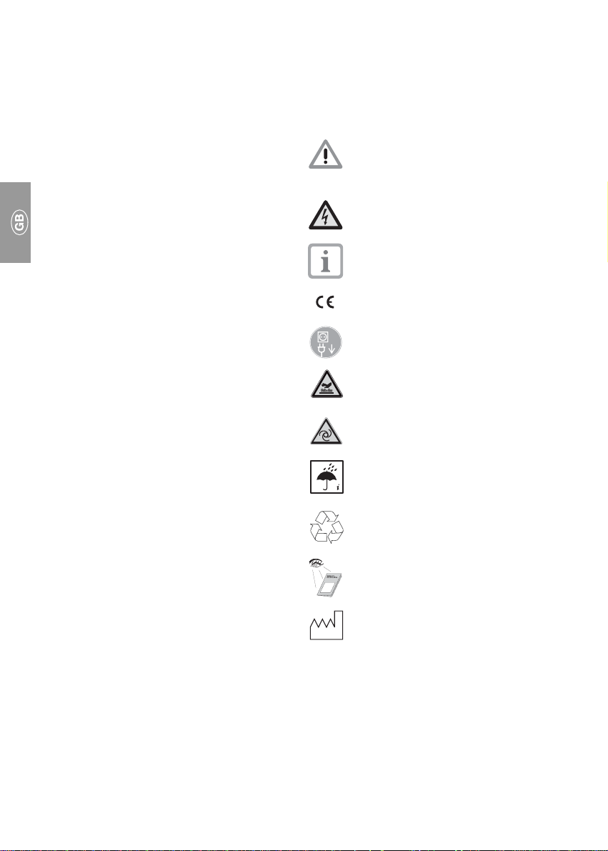
1.6 Warning Information and Symbols
In the Instructions for Assembly and Use, as
well as on the packaging and the product
itself, use is made of the following terms or
symbols to denote data or information of
special importance:
Information and/or mandatory
regulations or prohibitions for the
prevention of personal injury or
substantial property damage.
Warning of dangerous electrical
voltage.
Special information regarding the
economical use of the machine and
other information.
CE-Marking
Disconnect mains plug.
Caution! Hot surface.
Caution! Compressor can start up
automatically!
Make due allowance for environmental
effects. Do not operate the machine in
a damp or wet environment!
Recycling
Observe Instructions for Assembly and
Use!
Date of manufacture
4
Page 5
2. PRODUCT INFORMATION
2.1 Use for the Intended Purpose
The compressor is intended to be used for
generating compressed air required for
operating dental units of equipment or for
similar applications.
Installation in medical care facilities:
In designing and constructing the
compressor, allowance has been made for the
requirements of medical products where
applicable. Accordingly, the unit can be used
for installation in medical care facilities.
If the unit is installed in medical care facilities,
the requirements stipulated in Directive 93/42
EEC IEC 601-1 as well as the relevant norms
must be observed as applied to installation
and assembly.
2.2 Use other than that for the Intended Purpose
The compressed air produced by
the compressor is unsuitable for
operating breathing equipment or
similar facilities without additional
filters required for the operating
area.
• The compressors are designed to be
operated in dry, ventilated rooms, ambient
temperature +10 to +40 °C.
• Do not expose the compressor to rain. The
machine must not be operated in a damp or
wet environment. Use is also prohibited in
proximity to gases or combustible liquids.
• Prior to installing the compressor in medical
facilities, it must be ensured that the available medium complies with the requirements
stipulated for the relevant purpose in each
individual case. Observe the particulars
given in Chapter 4. "Technical Data".
When installing, classification and
conformity rating must be carried out by the
manufacturer of the ultimate product.
• Any other use or use beyond what is
specified is deemed to be not for the
intended purpose. The manufacturer
accepts no liability for damage resulting
therefrom. All risk is borne solely by the
operator/user.
2.3 Product Description
The compressor generates an oil-free, dry and
filtered compressed air required for operating
units of dental equipment.
3. SCOPE OF DELIVERY
Compressor with / without
dry-air system
Instructions for assembly
and use .................................... 9000-610-38/30
Accessories incl. pressure hose
ø 8x3x14, length 1 m.................... 5410-002-00
Only for compressors with dry-air system:
Collecting trough .......................... 3413-001-00
3.1 Special Accessories
The parts listed below are not included in the
scope of delivery.
Please order as required!
5150, 5151, 5170, 5171,
5250, 5251, 5270, 5271 ............... 5110-500-00
4151, 4251, 5351, 5451 ............... 4251-500-00
Pressure reducer ......................... 6040-992-00
3.2 Consumables
Filter cartridge suitable for compressor model:
Primo, Duo, Duo-Tandem,
Trio, Quattro, Quattro Tandem ..... 0832-982-00
Tornado ........................................ 5430-982-00
Fine-mesh filter for
dry-air system............................... 1610-121-00
Sterilisation filter for
dry-air System .............................. 1640-981-00
5
Page 6

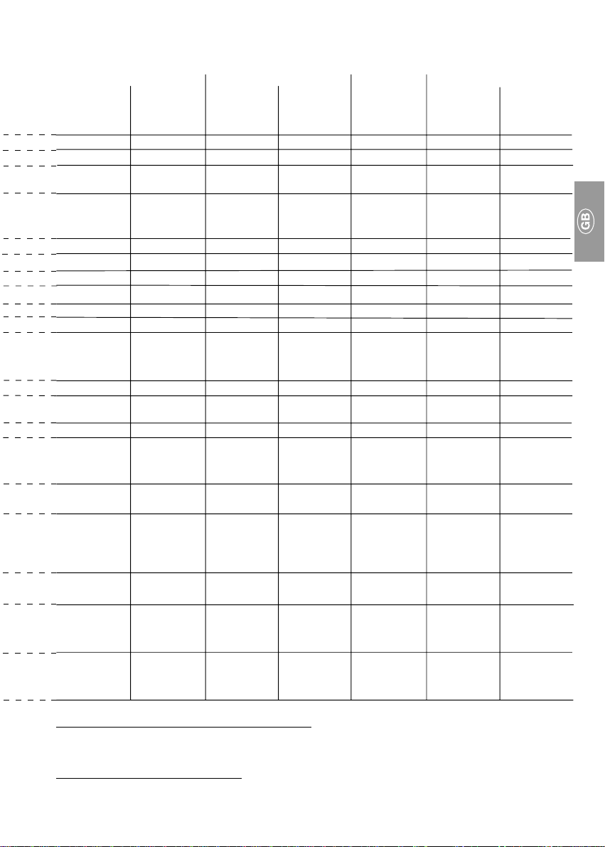
4. TECHNICAL DATA
Model Primo Duo Trio Quattro
5150-01a 5250-01a 5250-51a 5450-51a
5151-01b 5251-01b 5251-51b 5351-01b 5451-51b
Vol tage V 230 230 400 230 400
Frequency Hz 50 – 60 50 – 60 50 – 60 50 50 – 60
Current Consumption
at 8 bar A 4,3c – 4,4
Motor Protection Switch A
max. permissible setting 6,3 8,5 3,5 10,0 6,3
recommended setting 5,6c – 4,4
Rated Output kW 0,80c – 0,98
Speed min–11440c – 1710
Mains Fuse LS-10A
Protection System
Noise Level dB(A) 67c – 72
Number of Cylinders Zyl. 1 2 2 3 4
Delivery at 5 bar l/min
b
w. DAS
a
w/o. DAS
Switch-on/off Pressure bar 5,5 / 7,5 5,5 / 7,5 5,5 / 7,5 5,5 / 7,5 5,5 / 7,5
Safety V alve - Admissible
Operating Pressure bar 10 10 10 10 10
Volume of Pressure Tank l2020205050
Duty cycle %
b
w. DAS
a
w/o. DAS
Grade of Filtration, Cartridge
for compressor µm 10 10 10 10 10
Grade of Filtr., Fine-mesh Filter
for DAS µm 1 1 1 1 1
Grade of Filtr., Sterilised Filter
for DAS µm 0,01 0,01 0,01 0,01 0,01
Weight w. DAS
w/o. DAS
Dimensions
w. DAS
w/o. DAS
Charging Time 0 – 7.5 bar s
w. DAS
w/o. DAS
b
a
(H x W x D) cm
b
a
b
a
kg 56 57 57 90
c
c
c
c
d
IP 54 IP 54 IP 54 IP 54
c
c
60c – 70
c
60c – 70
6,3c – 7,0
6,5c – 7,6
1,30c – 1,60
1360c – 1600
LS-10A
71c – 75
110c – 120
115c – 130
c
c
c
c
d
c
3,1c – 2,5
3,2c – 2,5
c
8,6 4,4c – 4,8
8,6 4,4c – 5,0
1,40 1,90 2,20c – 2,95
LS-10A
c
d
1350 1440c – 1700
d
LS-10A
1410c – 1690
LS-10A
d
IP 54
c
c
c
72c– 76
110c – 120
115c– 130
c
c
c
77 75c – 77
165 23 0 – 2 60
– 235 – 270
c
50 50 50 50 50
100 100 100 _ _
47 49 49 87 –
64 x 49 x 46 64 x 49 x 47 64 x 49 x 47 86 x 74 x 51 86 x 74 x 51
64 x 49 x 44 64 x 49 x 45 64 x 49 x 45 – 70 x 74 x 50
c
135
– 120
125c – 105
c
c
75c – 65
65c – 55
c
c
75c – 65
65c – 55
c
c
130 95c – 80
––
c
c
c
c
c
a
w/o. DAS (without dry-air system)
b
w. DAS (with dry-air system)
c
depending on mains frequency
d
mains fuse: 10 A LS-switch, characteristics B, C, and D according to DIN EN 60898
6
Page 7
Duo Tandem Quattro Tandem Tornado 70 Tornado 130
4251-01b / 4680-51a 5170-01a 5270-01a 5270-02a
4151-51b 4251-51b 4641-51b 4681-51b 5171-01b 5271-01b 5271-02b
2 Aggregate 2 Aggregates 1 Aggregate 2 Aggregates
1 Aggregate
230 / 400 400 400 400 230 230 220
50 – 60 50 – 60 50 – 60 50 – 60 50 – 60 50 60
c
12,2c– 14,3
3,1c– 2,5
c
6,2c– 5,0
c
4,4c– 4,8
c
8,8c– 9,6
c
4,9c – 4,3
c
6,7 7,9
- / 3,5 3,5 6,3 6,3 6,3 8,5 10,0
6,5c–7,6c/3,2c–2,5c3,2c – 2,5
2,7c – 3,3c /
1,40 2,80c – 2,84
1410c – 1690c1410c – 1690c1440c – 1700c1440c – 1700c1420c – 1700
d
LS-10A
LS-10A
c
c
d
4,4c – 5,0
2,2c – 2,95
LS-10A
c
c
d
4,4c – 5,0
4,4c – 5,9
LS-10A
c
c
d
5,1c – 4,3
0,92c – 0,97
LS-10A
c
c
c
d
7 8,0
1,42 1,70
1380 1710
d
LS-10A
LS-10A
IP 54 IP 54 IP 54 IP 54 IP 54 IP 54 IP 54
72c – 76
c
75c – 77
c
74c – 76
c
76c – 79
c
67c – 70
c
70b – 72
a
72b – 75
2 x 2 / 2 2 x 2 4 2 x 4 1 2 2
215c – 240c / 220c – 240
c
110c – 120
– – 470c – 540
c
230c – 260
c
460c – 520
c
c
67c – 69
70c – 80
c
c
115 125
130 150
5,5 / 7,5 5,5 / 7,5 6,5 / 8,5 6,5 / 8,5 5,5 / 7,5 5,5 / 7,5 5,5 / 7,5
10 10 10 10 10 10 10
50 50 90 90 20 20 20
50 50 50 50 50 50 50
––––100100100
10 10 10 10 10 10 10
1111111
0,01 0,01 0,01 0,01 0,01 0,01 0,01
87 97 114 175 52 67 67
71 – – – 44 59 59
d
a
86 x 76 x 51 86 x 76 x 51 86 x 103 x63 86 x 103 x 63 64 x 49 x 46 64 x 49 x 46 64 x 49 x 46
– – – 75 x 103 x 63 64 x 49 x 44 64 x 49 x 44 64 x 49 x 44
171c – 147
c
––––100
86c – 76
c
165c – 135
c
76c – 66
c
130c –115
c
– 85
c
c
65 55
45 40
Climatic Conditions for Storage and Transport
Temperature –25 °C to +55 °C, 24h to +70 °C
Relative Atmospheric Humidity 10 % to 90 % (without condensation)
Climatic Conditions for Operation
Temperature +10 °C to 40 °C
Relative Atmospheric Humidity up to +70 %
7
Page 8
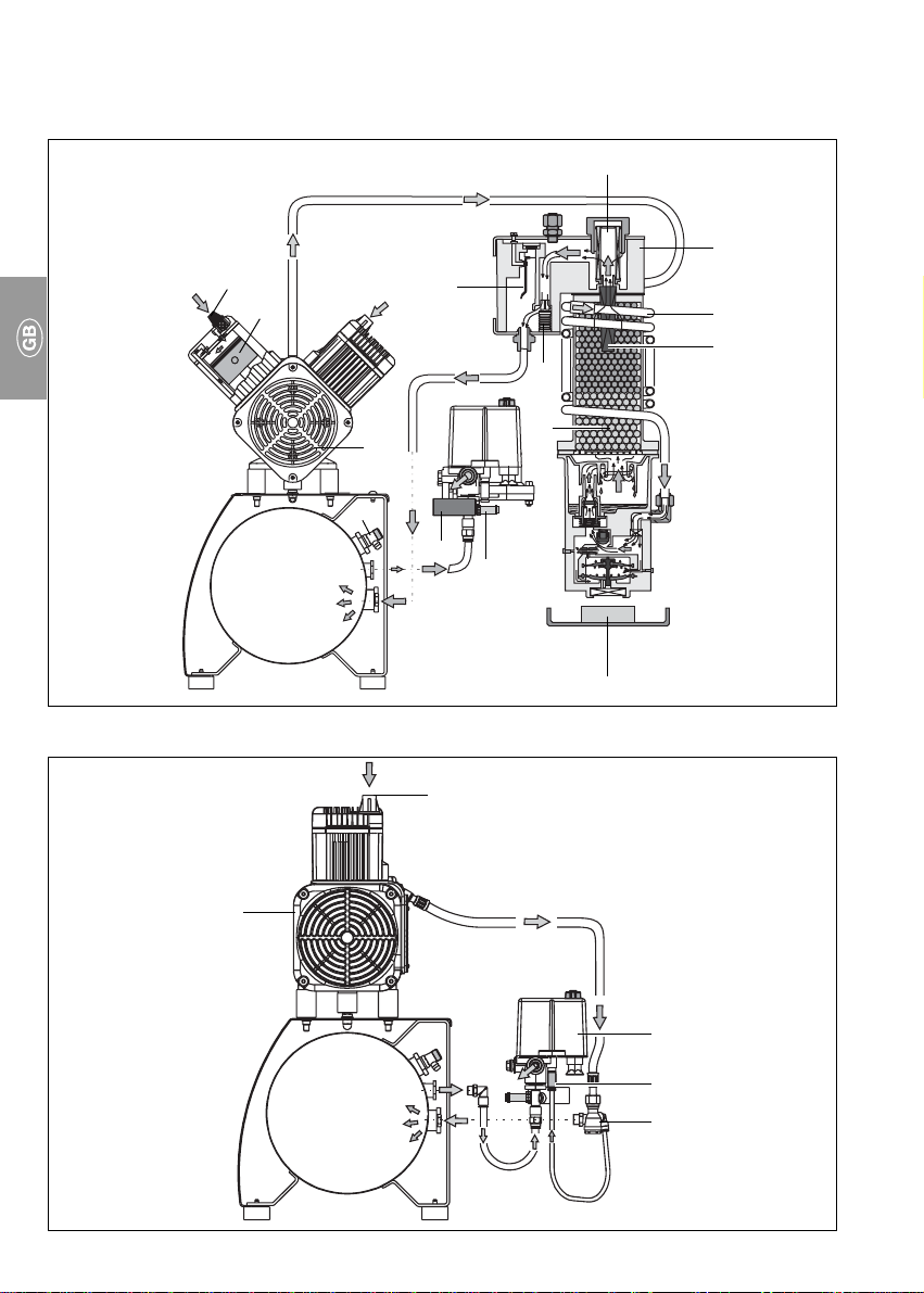
5. OVERVIEW OF FUNCTIONS OF COMPRESSORS
5.1 Compressor with Dry-air System
13
12
16
15a
1
2
3
4
10a
9
8
1
5.2 Compressor without Dry-air System
10b
13
11
7
14
6
5
11
17
15b
8
2
8
Page 9

6. FUNCTIONAL DESCRIPTION
6.1 Compressor with Dry-air System
Concise Functional Description:
The compressor aggregat (10a) draws in
atmospheric air which is then compressed
without any contamination by oil.
The compressor feeds the compressed oilfree air to the dry-air system (2).
The dry-air system removes moisture from the
compressed air.
Now in an dry state, the clean, oil-free air is
made available in the pressure tank (8) to the
consumers (e.g., turbine).
Detailed Functional Description:
• •
• Compressor Set
• •
Atmospheric air is drawn in via the intake
filter (13). The cylinder piston (12) of the
compressor set (10a) then compresses the
air. The inlet valve/outlet valve blocks the
direction of flow so that the compressed air
is forced to the dry-air system (2).
• Dry-air System
The compressed air is conducted round the
dry-air system via the spiral-shaped cooling
tube (3).
Inside the cooling tube, the compressed,
heated air cools down and a large percentage
of the moisture present in the air is extracted
in the form of condensation water.
This pre-dried air then passes into the
pressure tank (8) via the drier (14), sintered
metal filter (4), fine-mesh or sterilisation filter
(1) and non-return valve (15a).
The non-return valve (15)a serves to prevent
any backflow of the compressed air emerging
from the pressure tank.
Each time the compressor is switched off,
the condensation water is blown into the
water collecting (5) through by means of the
dry-air system and the pressure hoses are
vented on the compressor.
• •
• Regeneration of the Dry-air System
• •
The polyamide band (16) fitted inside the
hygrostat expands due to the presence of
humidity. If the permissible relative humidity
inside the pressure tank (8) is exceeded, the
valve on the hygrostat responds by opening, causing air to flow out of the pressure
tank in the opposite direction. This can be
heard blowing out underneath the dry-air
system (2). In this phase, the system undergoes a process of regeneration, for which
purpose the compressor must be at a
standstill. This process of regeneration will
continue to repeat itself until the relative
humidity originally set on the hygrostat (16)
is attained.
• •
• Valve Unit with Pressure Switch
• •
Whenever compressed air is withdrawn for a
certain consumer (e. g., turbine), the pressure
inside the tank is reduced. When the minimum
tank pressure set on the pressure switch (11)
is attained, the compressor will be switched
on again via the pressure switch. As soon as
the maximum tank pressure (7.5 bar) set on
the pressure switch is attained (5,5), the
compressor will switch itself off. The maximum permissible tank pressure of 10 bar is
marked in red on the pressure gauge (7).
The safety relief valve (6) serves to prevent the
maximum permissible tank pressure of
10 bar from being exceeded.
The drain cock (9) is used for draining off
condensation water from the pressure tank,
this being done by opening the valve.
Also refer to Section 12.3 "Draining Off
Condensation Water".
6.2 Compressor without Dry-air System
• •
• Compressor set
• •
The compressor set (10b) draws in atmospheric air via the suction filter (13) which is
then compressed without any contamination
by oil by means of the cylinder piston. The
inlet valve/outlet valve blocks the direction of
flow so that the compressed air is forced
through the non-return valve (15b) into the
pressure tank (8).
• Pressure Switch
The compressor set (10b) continues to feed
compressed air until the maximum pressure
preset on the pressure switch (11) is attained
inside the pressure tank (8) and the
compressor set switches itself off.
After the compressor set has switched itself
off, the pressure hoses are vented via vent
valve (17).
• •
• Valve Unit with Pressure Switch
• •
Refer to previous section, "Detailed Functional
9
Page 10

Description".
ASSEMBLY
7. STORAGE AND TRANSPORT CONDITIONS
The compressor leaves the factory
packed in a transport carton which
serves to prevent damage to the unit in
transit.
For transportation, always use the
original packing materials of the
compressor where possible. Always
transport the compressor upright.
When transporting the compressor
protect against damp, dirt and extreme
temperatures.
Compressors packed in original cartons
can be stored in warm and dry rooms
not exposed to dust.
As far as possible store the packing
materials in a safe place.
If storage of the packing materials is not
possible, ensure that they are disposed
of in a manner serving to protect the
environment. The transport carton can
be disposed of in the paper recycling
bin.
The compressor must always be
transported in the depressurised
state.
Prior to transport evacuate all air
from the pressure tank and pressure
hoses and definitely drain off
condensation water that is present
(refer to Section 8.8 "Draining Off
Condensation Water").
8. INSTALLATION AND PLACING IN INITIAL SERVICE
On compressors assigned to Test
Group 3 according to German Pressure-tank Regulations, e.g., models
Trio 5351-01 or Quattro 5451-51,
installation and initial placing in
service must only be carried out by a
suitably qualified engineer who is
required to provide an appropriate
record documenting such installation
in the form of an Installation
Certificate and to enclose this
document along with the other
compressor records.
Prior to placing in service for the
first time, all transport security
devices must be removed.
8.1 Environmental Conditions
• The unit may only be installed and operated
in dry rooms that are well ventilated and free
of dust.
• The compressor must be installed in such a
way that ease of access is warranted for
operation and maintenance as well as for the
rating plate.
• The unit must be mounted on a level floor
base revealing adequate stability. Observe
weight of compressor (refer to Chapter 4.
"Technical Data").
The suction side of the air filter as
well as the ventilation slats must be
kept unobstructed and reveal adequate spacing distance away from
walls (approx. 20 cm).
The mains connection line and the
air hoses must not reveal any bends
or kinks.
The room temperature must not be allowed to
fall below +10 °C as otherwise proper
functioning of the compressor will not be
warranted on account of the possibility of
undesirable condensation.
The room temperature must not be allowed to
exceed +40 °C. If room temperatures exceed
+40 °C provision must be made for additional
means of ventilation by a fan (see Fig. 3).
The ideal room temperature is from +10°C to
+25 °C.
Due to technical reasons, approx.
70 % of the electricity consumed by
the compressor set is converted to
heat and released into the environment.
The motor fan caters for effective ducted
cooling of the unit. To ensure this, the air must
be allowed to flow in and away without
obstruction of any kind. In unfavorable cases
or circumstances a forced ventilation system
will need to be installed (see Fig. 3).
No objects of any kind must be
allowed to come into contact with
the compressor since, at a room
temperature of, e.g., +40 °C, the
cylinders and cylinder heads are
liable to heat up to temperatures
exceeding +110 °C.
10
Page 11

Fire Hazards!
8.2 Compressed-air Connection
A standard feature of the compressor is a
control unit comprising the following:
pressure switch (11), safety valve (6),
compressed-air connection coupling (20) and
pressure gauge (7).
• Slip flexible pressure hose (ø 8x3x14) onto
connecting socket of pressure reducer and
secure with hose clip (21) to prevent
slipping off.
A flexible pressure hose fitted between
the firmly installed compressed-air
tube and the compressor serves to
3
prevent transmission of vibration and
thus reduces noise.
8.3 Electrical Connection
Connection up to the voltage supply
system may only be carried out by a
11
6
7
4
20
21
5
suitably qualified electrician
(with exception of those stations
supplied ready for plugging into an
earthing-contact type socket or CEE
socket, depending on the version of
the compressor).
The 400 V version of the compressor is
supplied fitted with a CEE connector, and the
230 V version with an earthing-contact type
plug. The regulations of local power supply
companies must definitely be observed.
The mains voltage and frequency must conform
to the data specified on the rating plate.
No connecting cable must be
allowed to run across the unit. The
hot surfaces of the compressor
might otherwise cause damage to
the cable insulation.
• If the unit is permanently connected up to
the voltage supply system, provision must
be made for a power disconnecting device
with a contact opening width of at least
3 mm (e.g., a power circuit breaker).
• If the unit is connected up to the voltage
supply system by means of a plug-type
connector, ease of access must be provided
to the socket for safety reasons, enabling
the unit to be disconnected safely from the
mains in cases where danger situations
arise.
• The corresponding circuit must be protected
by a fuse consisting of an LS-switch10 A
(characteristics B, C, and D) supplied and
11
Page 12

fitted by the client.
8.4 Placing in Initial Service
• Check to ensure that all transport security
devices have been removed from the
compressor.
• Check to ensure proper connection of the
compressed-air lines.
• The compressor must be properly
connected up to the voltage supply system.
• Check air filter for proper assembly.
• Switch on the compressor at the pressure
switch (11) by turning the rotary switch to
position "I AUTO" (refer to Fig. 6).
During the initial running hours, the
compressor may continue to switch
itself on again after shorter periods of
disuse – even if no air has been
withdrawn from the pressure tank.
During this phase, drying of the
pressure tank takes place while it
reveals excessive moisture content.
A blow-off noise can be perceived on
the silencer (dry-air system), from
which the absorbed moisture emerges
in the form of water vapor.
8.5 Setting the Motor Protection
Switch
In all compressor models except Duo-,
Quattro Tandem, motor protection switch and
pressure switch are combined into one
component (see Fig. 7). The motor protection
switch can be set by adjusting the setscrew
(31). Model Duo-, Quattro Tandem features
two separate motor protection switches which
are built into the control box of the
compressor set. These switches each have
a setscrew (35) as well as a start and stop
button (36 and 37).
All motor protection switches have been set at
the factory to certain values. These values are
equal to the recommended values given in
Chapter 4. "Technical Data" for a frequency of
50 Hz. The factory settings need to be
checked during installation. They should only
be changed if necessary.
When changing the settings, the
maximum values given in Chapter 4.
"Technical Data" must not be
exceeded.
For checking or resetting the motor protection
switch please proceed as follows:
• Remove protective housing of the pressure
switch (11) or, respectively, of the control
box of model Duo-, Quattro Tandem.
• Measure the maximum current (value shortly
before switch-off pressure is attained).
Measurements and adjustments can
only be carried out with the
compressor in the live state.
• Set the motor protection switch by adjusting
the setscrew (31 or 35, depending on
model) to the measured value.
8.6 Checking the Safety Valve
The safety valve has been set at the
factory to 10 bar, tested and confirmed by an endorsement stamp.
The valve must not be altered.
When placing the compressor in
service for the first time, the safety
valve must be checked for proper
functioning.
Give screw (6) a couple of turns in the
counter-clockwise direction until blow-off
occurs on the safety valve (refer to Fig. 9).
11
The safety valve should only be allowed to
blow freely
Turn screw (8-2) in clockwise direction to full
extent; the valve should now be in the fully
closed state once more (refer to Fig. 8).
for a short time.
During this check, the pressure tank
should be under pressure (maximum
7.5 bar).
The safety valve should never be
used for venting the pressure tank.
12
6
Page 13

8.7 Checking and Adjusting the Pressure Switch
The pressure switch has been set at the factory.
31
At 5.5 bar tank pressure the unit switches itself
on.
At 7.5 bar the unit switches itself off.
If required, the working pressure of the
compressor can be modified at the
32
33
7
35
36
37
8
pressure switch.
To do this, it is necessary to first set the switch-off
pressure and afterwards the switch-on pressure
via pressure-difference (∆p).
When carrying out this work, the
protective housing of the pressure
switch (11) needs to be removed.
Settings can only be carried out with
the compressor in the live state.
Proceed to set the
the adjusting screw (32, refer to Fig. 7): plus (+)
direction of arrow = higher and minus (–)
direction of arrow = lower. When making this
adjustment, the pressure difference also
undergoes modification (readjust if necessary).
Observe maximum pressure
(10 bar) on safety valve. The switch-off pressure
must be at least 0.5 bar below the value of the
safety valve as otherwise the safety valve would
open and the compressor set would then fail to
attain the switch-off pressure, thus continuing to
run all the time.
The pressure difference ∆p
switch-on and switch-off pressure can be
modified. This is done by turning the adjusting
screw (33) in the plus (+) or minus (–) direction.
When carrying out this adjustment, the pressure
tank must be under pressure.
switch-off pressure p
between
on
8.8 Draining off Condensation Water
During transportation, condensation water may
form inside the pressure tank due to differences
in temperature. Each time a compressor is
installed, always drain off the condensation water
first; this also applies to compressors
incorporating a dry-air system.
When doing this, proceed as follows:
9
• With the compressor in the switched-on
6
state and at tank pressure, proceed to screw
open the condensation-water drain cock (9).
• Wait until the condensation water has
completely drained off from the pressure tank.
• Close drain cock (9) again.
9
13
Page 14

This may otherwise impair proper
functioning of the safety valve.
X1 Mains connection 1/N/PE AC 230 V
M1 Compressor motor
9. CIRCUIT DIAGRAMS
9.1 Version 1/N/PE AC230 V
List of Equipment
Q1 Pressure switch/motor
protection switch
10
M2 Proposed fan connection
(can be allocated if required)
9.2 Version 3/N/PE AC 400 V
List of Equipment
Q1 Pressure switch/motor
protection switch
X1 Mains connection 3/N/PE AC 400 V
14
11
Page 15

9.3 Version 3/N/PE AC 400 V, 2 Aggregates, Duo Tandem
I>
I>
List of equipment
Q1 Pressure switch
Q2,Q3 Motor protection switch
X1 Mains connection 3/N/PE AC 400 V
Q1
12
X1
246
135
L1
L2L3NPE
P>
A1
X2 Connection to A1
X3, X4 Connection A1 to M
M1,M2 Compressor motors 1 and 2
A1 Control
333222111777PE PE PE
X2
333222111777PE PE PE
22
14
246
Q2
X3
M1
135
3
2
3
M
3
13
21
4466PEPE112
9.4 Version 3/N/PE AC 400V, 2 Aggregates, Quattro Tandem
List of equipment
A1 Control
K1 Time lag relais
Q1
35
1
P>
2
64
A1
M1, M2 Compressor motors 1 and 2
Q1 Pressure switch
Q2, Q3 Motor protection switch
X1 Mains connection 3/N/PE AC 400 V
X2 Connection to A1
X3, X4 Connection A1 to M
PE
5
4
4
5
5
4
X2
5
5
5
4
4
4
PE
Q3
X4
M2
246
135
3
M
3
22
211413
4466PEPE11223
13
X1
L1L2L3NPE
Q2
13 21
22
14
I>I>I>I>I>
4-6,3A
5
3
1
21
3
64
PE
X3
U
PE
V
W
M
M1
3~
K1
531
A1246
6
24
A2
4-6,3A
X4
M2
246
I>I>I>I>I>
1
3
U
M
3~
13 21
1422
5
3
4
2
6
1
PE
PE
V
W
15
Q3
Page 16

14
M1 Compressor motor
M2 Proposed fan connection
(can be allocated if required)
USE
10. OPERATION
In dangerous situations always
unplug the unit from the mains
(disconnect plug from mains).
The surfaces of the compressor are
hot. There is a risk of burns being
sustained if these surfaces are
touched.
Automatic start-up. Whenever the
pressure inside the pressure tank
drops, this will result in the
compressor being switched on
automatically and remaining on until
25
11
7
the maximum operating pressure of
7.5 bar is attained once more.
10.1 Switching on the Compressor
• Switch on the compressor at the pressure
switch (11) by turning the switch (25) to
position "I AUTO".
This starts up the compressor set and the
pressure tank is filled. As soon as the switchoff pressure is attained, the compressor set
will switch itself off automatically.
The maximum permissible operating pressure
must not be exceeded. The permissible
operating pressure is marked by a red stroke
on the mounted pressure gauge (7).
In the event of the maximum operating pressure (10 bar) being exceeded, the compressor set must
be switched off and disconnected
from the mains (disconnect mains
16
Page 17

plug). Inform the technician responsible.
11. MAINTENANCE INTERVALS – USER / TECHNICIAN
Maintenance due to be carried out Chapter Interval
• Setting the pressure reducer 12.2 Once a year
• Draining off condensation water 12.3
Compressors without dry-air system Once a month
At a high degree of humidity Once a day
Compressors with dry-air system Check every six months,
• Safety-valve check 12.4 Every six months
• Filter replacement 12.5 Once a year
draining if necessary
12. MAINTENANCE
Repair work exceeding normal
maintenance operations may only be
carried out by a suitably qualified
engineer or our customer service
staff.
Only use spare parts licensed by the
manufacturer as well as accessories
destined for the purpose.
Prior to performing any maintenance
or repair work, be absolutely sure to
switch off the compressor first and
disconnect from mains (pull out
mains plug).
To ensure proper functioning of the compressor, be sure to regularly carry out maintenance as described in Sections 12.1 to 12.5.
15
12.1 Pressure Reducer
This part is sold as a special accessory
item and is therefore not included in the
scope of delivery.
The pressure reducer (40) serves to control the
flow pressure in alignment with the desired
working pressure. The pressure reducer is
connected to the pressure switch via an
express coupling (20).
20
40
17
Page 18

16
17
18
12.2 Setting the Pressure Reducer
To set the flow pressure, place the syringe,
turbine, etc. in operation. Lift the rotary
adjusting knob (41) and continue to turn in the
41
direction of the + arrow (to increase flow
pressure) or in the direction of the – arrow (to
reduce pressure) until the required flow
pressure is indicated on the pressure gauge
(42). Afterwards push the adjusting knob
back in position making sure that it firmly
40
engages in place so as to prevent
displacement of the pressure reducer. The
set pressure is now fixed.
For flow pressure refer to data specified by the
manufacturer of the consumers (e.g., turbine).
42
12.3 Draining off Condensation Water
On compressor versions fitted with
system, the condensation water is discharged
automatically through the dry-air system.
On compressor versions without a dry-air
system it is necessary to drain off the
condensation water at least once a month!
In countries having a high degree of
atmospheric humidity, the condensation water
needs to be drained off every day!
Procedure:
• With the compressor in the switched-on state
9
and maximum tank pressure, proceed to
screw open the condensation-water drain
cock (9) as far as possible.
• Wait until the condensation water has
completely drained off from the tank.
• Close drain cock (9).
a dry-air
12.4 Checking the Safety Valve
The safety valve (6) has been set at
the factory to 10 bar, tested and
confirmed by an endorsement stamp.
The valve must not be altered.
Give screw (26) a couple of turns in the
counter-clockwise direction until blow-off
occurs on the safety valve.
6
The safety valve should only
blow off for a short time.
26
Turn screw (26) in clockwise direction to full
extent; the valve should now be in the fully
closed state once more.
During this check, the pressure tank
should be under max. pressure (7.5 bar).
The safety valve should never be
used for venting the pressure tank.
This may otherwise impair proper
functioning of the safety valve.
be allowed to
18
Page 19

19
20
12.5 Filter Replacement
Used filters must not be cleaned
but must be replaced by new ones.
Attempting to clean destroys filters.
The intervals in which the filter
13a
13b
1
cartridges need replacing will depend
essentially on the amount of dust
contained in the air.
Regular filter replacement serves to
preserve the high quality of the
compressed air over a longer period
of time apart from enhancing the
service life of the compressor.
Subject to proper installation (refer to
Section 8.1 "Environmental
Conditions"), we recommend that all
filters on the compressor and the dryair system be replaced once a year.
Order numbers for filter cartridges:
Compressor types 5170, 5171, 5270, 5271
Suction filter (13a) ........................ 5430-982-00
Compressor types
4151, 4251, 4641, 4681, 5150,
5151, 5250, 5251, 5351, 5451
Suction filter (13b) ........................ 0832-982-00
Compressors with dry-air system types
4151, 4251, 4641, 4681, 5151,
5171, 5251, 5271, 5351, 5451
Fine-mesh filter (1) ....................... 1610-121-00
or
Sterilisation filter* (1) .................... 1640-981-00
When replacing filters, the supplied
sticker and documentation recording
the last filter replacement should be
filled out with the appropriate
information and stuck in a visible place.
Also refer to the information enclosed
in the pack containing the new filters.
21
* A sterilisation filter serves to eliminate any
additional contamination caused by microorganisms such as bacteria, fungus spores
and viruses which may be present in the
ambient atmoshere.
19
Page 20

22
13. SHUTTING DOWN THE UNIT
If the compressor is not used for a longer
25
period of time, it is recommended that the
condensation water be drained off from the
pressure tank. Afterwards put the compressor
into operation for approximately 10 minutes
with the condensation-water drain cock (9) in
9
the open state. Then switch off the unit on the
pressure switch (25), close the condensationwater drain cock and disconnect the mains
plug.
DISPOSAL
14. DISPOSAL OF THE MACHINE
• Disconnect mains plug.
• Let off air pressure in compressed-air tank
by opening the condensation-water drain
cock (9).
• Dispose of the compressor in accordance
with local valid regulations.
20
Page 21

TROUBLE SHOOTING
15. TIPS FOR USERS
1. Compressor fails
to start up.
2. Compressor fails
to switch off.
3. Compressor
switches on from
time to time without air being withdrawn for any
consumer.
ing or loud noises
coming from
compressor.
Possible CauseFault
• Absence of mains power.
• Pressure switch not
switched on.
• Compressor under-dimensioned,
excessive air withdrawal
(per treatment site approximately
50 ltr/min)
• Leakage in compressed-air line
system.
• Air escaping downwards via the
dry-air system (regeneration
phase).
• Leakage in compressed-air line
system.
• Bearing damage.
Removal of Fault
• Check mains fuse, if necessary,
switch unit back on again
(if fuse is defective, replace).
• Switch on pressure switch.
• Notify technician.
• Ascertain air requirements,
using a larger compressor if
necessary.
• Detect leak and seal.
• Notify technician.
• Dry-air system is in regeneration
phase, humidity being reduced in
tank.
• Detect leak and seal.
• Notify technician.
• Notify technician.4. Sound of knock-
5. Decline in feed
performance,
compressor runs
longer to charge
tank. For
charging times
refer to Chapter 4
"Technical Data".
6. Water is dripping
out of the air consumers (e.g.,
turbine).
• Suction filter contaminated. • Replace suction filter once a
• Condensation water in pressure
tank.
year at least. Never clean the
suction filter.
• Drain off condensation water from
tank at least once a month. This
should be done once a day in
areas where a high degree of
humidity prevails or in tropical
countries. Carefully observe
ambient temperature of
compressor (refer to Section 8.1
"Environmental Conditions").
21
Page 22

16. TIPS FOR TECHNICIANS
The following trouble shooting guide is intended solely for technical staff. Repairs
may only be carried out by technicians.
Fault
1. Compressor fails
to start up.
Possible Cause
• Absence of mains power.
• Pressure switch not
switched on.
• Under voltage/Over voltage.
• Motor protection switch set
too low.
• Motor protection switch
defective.
• Air-relief valve defective,
compressor set starting up
against pressure (only
compressors without
dry-air system).
• Set reveals mechanical
sluggishness, piston stuck
(motor protection switch
trips)
Removal of Fault
• Check mains fuse, switch unit
back on again if necessary (if fuse
is defective, replace). Check mains
voltage.
• Switch on pressure switch.
If the pressure switch remains
switched on for a brief duration
and does not switch the motor off
until afterwards, the current
consumption on the 3-phase
current needs to be checked in all
three phases or in one phase on
AC current.
• Measure voltage, notifying the
electrician if necessary.
For a detailed description
refer to Section 8.5 "Setting
the Motor Protection Switch".
• Measure current. Set motor
protection switch accordingly (refer
to Chapter 4. "Technical Data").
• Check motor protection switch,
replacing if necessary.
• Check to see whether the air-relief
valve produces blowoff after the
set is switched off. Render
operable or replace.
• Disconnect mains plug, remove
crankcase cover on compressor
that has heated and turn fan
wheel; if this is not possible,
replace piston and cylinder or
complete set.
Users of model Duo-,
Quattro Tandem may
temporarily utilize only one
aggregate.
22
Page 23

Fault
23
24
Possible Cause
50
51
52
53
54
50
Removal of Fault
To do this, please proceed as follows:
– Remove mains connection.
When one of the aggregates of model
Duo-, Quattro Tandem is malfunctioning, the button "I" of its motor
protection switch is released. In
addition, the rotary switch of the
pressure switch jumps into position "0
OFF". To disconnect the defective
aggregate, please pull one the mains
plug on top of the control box which
is directly above the released switch
(see Fig. 23). In order to temporarily
operate the remaining aggregate set,
set the rotary switch of the pressure
switch back to position "I AUTO".
– Disconnect defective aggregate
pneumatically.
Remove pressure hose (54), Tconnector (53) and connector (52).
Connect functioning aggregate and
dry-air system by directly joining
pressure hose (51) and the elbow
(50) fitted to this aggregate.
• Substitute for defective aggregate.
Unplug the unit from the
mains.
– Turn rotary switch of the pressure
switch to position "0 OFF".
– Depressurize tank via condensa-
tion-water drain cock. Afterwards
close cock again.
– Replace defective aggregate by a
new one.
– Replug unplugged plug on top of the
control box.
– Remove cover of the control box. To
do this, turn the two screws(55)
counterclockwise to the stop.
– Press button "I" of the released
motor protection switch.
– Put cover back on and screw tight.
– Plug in mains plug.
– Turn rotary switch of the pressure
switch to position "I AUTO".
– Test run the system.
23
Page 24

Fault
2. Compressor fails
to switch off.
Possible Cause
• Lamellar valve (inlet / outlet
valve) between cylinder and
cylinder head defective.
Removal of Fault
• Dismantle cylinder head and
install new lamellar valve.
3. Compressor
switches on from
time to time
without air being
withdrawn for any
consumer.
4. Sound of knocking
or loud noises
coming from
compressor.
• Air escaping on air-relief valve
(only on compressors without
dry-air system).
• Air blowing through dry-air
system into collecting trough.
• Leakage in compressed-air line
system.
• Compressor under-dimensioned;
excessive air withdrawal,
• Compression collar worn on
piston.
• Air escaping downwards via the
dry-air system.
• Non-return valve defective.
Air escaping via the dry-air
system.
Air escaping at relief valve on
compressors not incorporating a
dry-air system.
• Leakage in compressed-air line
system.
• Bearing damage.
• Replace air-relief valve.
• Check control head on dry-air
system.
• Bring pressure to act upon lines.
Seal leak, if necessary.
• Ascertain air requirements (per
treatment site approx. 50 ltr/min).
Use a larger compressor, if
necessary.
• Replace piston and cylinder or
complete set.
• Dry-air system is in regeneration
phase; atmospheric humidity
being reduced in tank.
• Check non-return valve to see
whether air is escaping. Clean or
replace non-return valve.
• Detect leak and seal.
• Check motor shaft bearings and
crankshaft bearings, replacing if
necessary.
5. Decline in feed
performance,
compressor runs
longer to charge
tank. (For charging
times refer to
Chapter
4. "Technical
Data").
24
• Suction filter contaminated.
• Lamellar valve (inlet/outlet valve)
defective.
• Compression collar worn on
piston.
• Replace suction filter once a year
at least. Never clean suction
filter.
• Replace cylinder head and valve
plate.
• Replace piston and cylinder or
complete set.
Page 25

Fault
6. Water is dripping
out of the air
consumers
(e.g., turbine).
Possible Cause
• Condensation water in tank.
Removal of Fault
• Drain off condensation water
from tank at least once a month.
This should be done once a day
in areas where a high degree of
humidity prevails or in tropical
countries.
Refer to Section 12.3
"Draining off Condensation
Water".
Carefully observe ambient
temperature of compressor.
Refer to Section 8.1
"Environmental Conditions".
7. Compressor is
running and
compressed air is
being blown off
via the dry-air
system.
25
• Congestion of control nozzle on
dry-air system.
• Control unit defective.
60
61
62
63
64
60
63
65
• Remove screws (63) from control
unit and clean control nozzles
using cleaning pin (60).
• Replace control unit.
For maintenance work or in the
event of defects occurring, the
control unit (64) can be
dismantled on the dry-air system.
– Dismantle dry-air system on
compressor.
– Remove three hexagon socket
screws (65) from base of dry-air
system.
– Remove control unit (64).
– Remove O-rings (62) from base
of water collecting chamber and
replace by new ones.
– Remove valve together with
sealing washer and compression
spring (61) and substitute by
supplied parts.
25
Page 26

Fault
8. Failure on dry-air
system.
26
Possible Cause
• Control unit defective.
Removal of Fault
• Replacement of control unit;
alternatively and temporarily:
• Bridge over the dry-air system.
In the event of failure occurring on
the dry-air system, this can be
bridged over so to enable work to
continue with the compressor.
If the dry-air system is bridged over,
action should be taken to ensure its
speedy repair. Meanwhile
condensation water should be
drained off at least once a day.
Draining off condensation water:
– Switch on compressor and wait for a short
time until switch-off pressure is attained.
– Open drain cock (9) by turning in the
70
71
72
73
74
counter-clockwise direction until escaping
air is able to entrain water from the
pressure tank.
Refer to Section 12.3 "Draining off
Condensation Water".
– Wait until no further water is blown out of
the drain cock.
– Close drain cock again.
Bridging over the dry-air system:
– Disconnect compressor from mains so as
to prevent it from starting up while
rebuilding operations are in progress.
For this:
Unplug the unit from the mains.
26
27
– Drain compressed air from pressure tank
72
75
73
76
(open drain cock (9), refer to Fig. 16).
– Remove screw (74). Remove washer and
save for later use (needed again after
repair). Fit screw (74) again, screwing
back in to full extent.
By removing the washer, the screw
presses against a metal plate and
thus closes the duct governing
regeneration.
– Screw off cap nut (70) and remove conical
nipple (71) from threaded joint (73).
To prevent loss of cap nut and
conical nipple, these parts should
be attached to the threaded joint of
the cooling tube during bridge-over.
Page 27

Fault Possible Cause
Removal of Fault
– Screw off pressure hose (72) from
compressor set on dry-air system and
screw onto threaded joint (73).
– Remove screw plug (75) along with filter
(76), turn 180° and insert. Tighten screw
plug (75).
This action serves to seal off the
duct to the dry-air system, and the
control head on the dry-air is
vented during stoppage through a
small borehole drilled into the plug
screw (75).
27
 Loading...