

Page 1
INSTALLATION AND OPERATING INSTRUCTIONS
1999/12
DÜRR AMALGAM SEPARATOR AZ 50
25
Page 2

26
Page 3

CONTENTCONTENT
CONTENT
CONTENTCONTENT
Important information
1. Note......................................................... 26
1.1 CE-marking ...................................... 26
1.2 General Information .........................26
1.3 Electromagnetic Compatibility ........ 26
1.4 General Safety Information .............. 26
1.5 Electric Safety Instructions ..............26
1.6 Warning Information and Symbols .. 27
2. Product information .............................. 27
2.1 Use for the Intended Purpose ......... 27
2.2 Use other than that for the Intended
Purpose ........................................... 27
2.3 Product Description.........................27
3. Overview of models .............................. 28
4. Scope of delivery................................... 28
4.1 Special Accessories ........................28
5. Technical Data ....................................... 29
6. Overview of functions ........................... 30
7. Functional description .......................... 31
7.1 Method of Functioning..................... 31
7.2 Amalgam separation Separation..... 31
7.3 Filling Level Measurement .............. 31
7.4 Equipment Failure ........................... 32
7.5 Service Button ................................. 32
Assembly
8. Installation hints ....................................33
8.1 Installation Room ............................. 33
8.2 Installation Site ................................ 33
8.3 Combination Facilities ..................... 34
8.4 Planning a Pressure Equalising Pipe or
Air Demixer ......................................34
8.5 Hose Material .................................. 34
8.6 Hose Laying .................................... 34
8.7 Odour Trap ......................................35
9. Installation of AZ 50 .............................. 35
9.1 Fixing the AZ 50 in Place ................ 35
9.2 Fixing the Pressure Equalising Pipe in
10. Electrical connection............................. 36
11. Putting into operation ........................... 37
12. Tips for tracing faults............................ 38
Place ................................................35
10.1 Mains Connection via Earthing-
Contact Type Socket ....................... 36
10.2 Fixed Mains Connection ..................36
10.3 Electrical Connection in AZ 50 ........36
10.4 Display Module................................37
11.1 Functional Check ............................. 37
11.2 Visual Check ................................... 37
11.3 Service Button .................................37
11.4 Emergency Program ....................... 37
13. Service-Programm ................................ 40
Functional sequence ........................... 41
13.1 Start .................................................41
13.2 Indicator Test .................................. 41
13.3 Safety Switch ..................................41
13.4 Motor Running and Braking Action 41
13.5 Sediment Scanning ........................41
13.6 Output Signals ................................41
13.7 Stop .................................................41
14. Transport of the AZ 50 ........................ 42
Use
15. Operation................................................43
15.1 Ready for Operation State ...............43
15.2 Amalgam Collecting Vessel
95% full ............................................43
15.3 Amalgam Collecting Vessel
100% full ..........................................43
15.4 Fault ................................................. 44
16. Cleaning and disinfection..................... 44
17. Replacing the amalgam
collecting vessel.................................... 44
17.1 BEFORE replacing the amalgam
collecting vessel, please observe the
following:.......................................... 44
17.2 Replacement of Amalgam Collecting
Vessel .............................................. 44
17.3 Disposal of Amalgam Collecting
Vessel .............................................. 44
18. Maintenance........................................... 45
18.1 Annual Testing of Indicators on
Display Module ................................ 45
18.2 Testing for Proper Working Order -
Every 5 Years...................................46
18.3 Inspection of the Centrifugal Pump -
Every 2 Years...................................46
19. Disposal of the machine .......................46
Spare parts
AZ 50 ....................................................... 48-49
27
Page 4

IMPORTANT INFORMATION
1. NOTE
1.1 CE-marking
•CE-marking in accordance with the
Machinery Directives.
•The product bears the CE-marking
in accordance with the directive governing
Machinery Directives 89/392/EWG and
conforms to the basic requirements of that
Directive.
1.2 General Information
• The Installation and Operating Instructions
form an integral part of the machine. They
must be kept close to the machine and in
readiness whenever required. Precise
observance of these instructions is a prior
condition for use of the machine for the
intended purpose and for its correct
operation.
• Safety for the operator as well as troublefree operation of the machine are only
ensured if use is made of original equipment
parts. Moreover, use may only be made of
those accessories that are specified in the
technical documentation or that have been
expressly approved and released by Dürr
Dental for the intended purpose.
If and where use is made of accessories or
consumer supplies from outside sources,
Dürr Dental are unable to assume any
guarantee for safe operation or safe
functioning.
• No warranty claims are accepted in respect
of damage arising from the use of
accessories or consumer supplies from
outside sources.
• Dürr Dental only regard themselves as
being responsible for the machines
regarding safety, reliability and proper
functioning if assembly, resettings, changes
or modifications, extensions and repairs
have been carried out by Dürr Dental or an
agency authorised by Dürr Dental and if the
machine is used in conformity with the
Installation and Operating Instructions.
• The Installation and Operating Instructions
conform to the relevant version of the
machine and the underlying safety
standards valid at the time of going to press.
All proprietary rights are reserved in respect
of the specified circuitry, methods, names,
software programs and equipment.
• Any reprinting of the technical
documentation, in whole or in part, is
subject to written prior approval of Dürr
Dental.
1.3 Electromagnetic Compatibility
EN 60601-1-2 and IEC 1000-4-3 EN Standards governing Electromagnetic
Compatibility - Medico-electrical Equipment
are fully complied with.
1.4 General Safety Information
• Dispose of the packaging material in the
proper manner, and make sure that it is kept
out of the reach of children.
• The product is classified as medicotechnical equipment and may only be used
by such persons as can guarantee that they
will handle it properly on account of their
training and/or technical knowledge.
• Each time prior to using the machine the
user must check to ensure that it is
functionally safe and in proper condition.
• The user must be familiar with how to
operate the machine.
• The product is not intended for use in areas
of rooms employed for medical purposes
that are exposed to risk of explosion.
Explosion hazards may result from the use
of inflammable anaesthetics, skin cleansing
agents, oxygen and skin disinfectants.
Moreover the machine is only suitable to a
limited extent for operation in a combustionstimulating atmosphere.
1.5 Electric Safety Instructions
• The AZ 50 must be connected up to a
properly installed earthing-contact type
socket. For fixed connections please
observe points 9 and 10 of these
instructions.
• Prior to connecting up the machine a check
must be carried out to see whether the
mains voltage and mains frequency
specified on the machine conform to the
data applicable to the supply mains.
• No extension cables or leads must be used
for power supply purposes.
28
Page 5
• Prior to being put into operation, the
machine and the lines
for damage. Damaged lines, socket outlets
and plugs must be replaced immediately.
• Never touch the patient and non-protected
socket outlets or plugs of the machine at the
same time!
need to be inspected
for damage resulting therefrom. All risk is
borne solely by the user.
Use for the intended purpose includes
observance of the Installation and Operating
Instructions as well as the installation,
operating and maintenance conditions.
The machine must not be used in
operating rooms.
1.6 Warning Information and Symbols
In the Installation and Operating Instructions
use is made of the following terms or symbols
to denote data or information of special
importance:
Angaben bzw. Ge- und Verbote zur
Information and/or mandatory
regulations or prohibitions for the
prevention of personal injury or
substantial property damage.
Warning of dangerous electrical
voltage.
Special information regarding the
economical use of the machine and
other information
Floating Application Part Type BF
CE Marking without Notified Body
Number
Observe Instructions for Use
To protect operating personnel
working on the AZ 50, protective
gloves must be worn.
2. PRODUCT INFORMATION
2.1 Use for the Intended Purpose
The function of the Dürr Amalgam Separator is
to separate and intercept heavy metals and
amalgam dust drawn off by dental suction
equipment in the form of fillings that have
been drilled open.
The amalgam separator is intended for
installation of a maximum number of two
treatment units in dental surgeries or dental
clinics.
Any other use or use beyond what is
specified is deemed to be not for the intended
purpose. The manufacturer accepts no liability
2.2 Use other than that for the
Intended Purpose
Any other use or use beyond what is
specified is deemed to be not for the intended
purpose. The manufacturer accepts no liability
for damage resulting therefrom. All risk is
borne solely by the user.
2.3 Product Description
Among other substances, heavy metals and
amalgam dust accumulate, drawn off by
dental suction equipment in the form of fillings
that have been drilled out. Biodegradation of
amalgam that has found its way into the
waste-water system is a difficult undertaking.
To reduce contamination in waste water
caused by heavy metal stemming from dental
treatment equipment, it is essential - in
compliance with the General Sewage Administration Regulations (Annex 50, Dental
Treatment) in force in Germany - to install
amalgam separators ahead of the dental
waste-water drain furnished with a seal of
approval issued by the German Institute of
Structural Engineering in Berlin.
The AZ 50 Amalgam Separator has been
designed by Dürr Dental to produce the
required separation efficiency factor of over 95%
proceeding based on a rate of flow of 8 ltr./min.
Amalgam slurry is intercepted in an amalgam
collecting vessel underneath the centrifuge
drum. Depending on the volume accumulating,
the amalgam collecting vessel needs replacing
once or twice a year.
The AZ 50
used in conjunction with a Dürr Suction Unit
VS 300.
The AZ 50
employed in connection with water ring pumps.
withoutwithout
without Pump (Model 7112-01) is
withoutwithout
withwith
with Pump (Model 7112-02) is
withwith
29
Page 6

3. OVERVIEW OF MODELS
4. SCOPE OF DELIVERY
Amalgam Separator
AZ 50 without Pump.......................... 7112-01
Amalgam Separator
AZ 50 with Pump ............................... 7112-02
Amalgam Separator AZ 50
without Pump..................................... 7112-01
Amalgam Separator .................... 7112-100-50
Pressure Equalising Pipe ............ 7112-101-00
Accessories, complete ............... 7112-001-00
Installation and Operating
Instructions AZ 50 .................. 9000-605-95/01
Instructions for Use - Disinfection
and Cleaning of Suction Systems 9000-605-10
Amalgam Separator AZ 50
with Pump ..........................................7112-02
Amalgam Separator .................... 7112-100-51
Accessories, complete ............... 7112-001-00
Installation and Operating
Instructions AZ 50 .................. 9000-605-95/01
Instructions for Use - Disinfection
and Cleaning of Suction Systems 9000-605-10
4.1 Special Accessories
The parts listed below are
scope of delivery.
Please order as required.
Base for PAL 14 .......................... 7112-992-00
Base for PAL 50 .......................... 7112-993-00
Hood ............................................ 7112-200-00
Remote Indicator ......................... 7110-994-00
Test Set, complete ...................... 7110-064-00
notnot
not included in the
notnot
30
Page 7
7112-01
7112-02
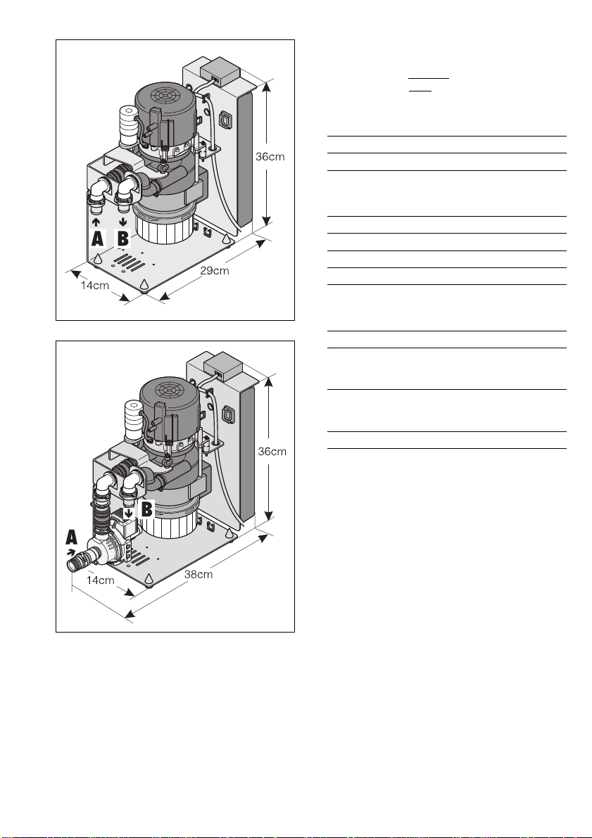
5. TECHNICAL DATA
Model 7112-01 without Pump
Model 7112-02 with Pump
Electrical Rating
Voltage (V) 230
Frequency (Hz) 50
Max. Current Consumption (A) 1,7
Centrifuge Motor
Voltage (V) 230
Frequency (Hz) 50
Max. Current Consumption (A) 0,95
Rated Speed (1/min) 2780
Rated output (W) 90
Elektronic System
Protective Low Voltage (V) AC/DC24
Current Delivery (A) max.0,7
Rate of Flow
Volume of Secretion (l/min) max. 8
Amalgam Collecting Vessel
Usable Volume (ccm) ca.150
Replacement Interval (Monate) ca. 6-9
A Vakuum-Anschluß, Schlauch D=25mm
B Abwasser-Anschluß,Schlauch D=25mm
Dimensions
7112-01: D = 14cm, L = 32,8cm, H = 36cm
7112-02: D = 14cm, L = 38cm, H = 36cm
Temperature Range
Machine in operation ....... +10 to +40 °C
Storage and transport .......... -25 bis +70 °C
Atmospheric Humidity
Machine in operation ...................... max. 80%
Storage and transport ..................... max. 95%
Weight
7112-01 ................................ approx. 7.5 kg
Inspection label
• CE-label
• Institut für Bautechnik, Berlin:
General Structural Supervisory Approval
with Inspection label: Z-64.1-13
• Electromagnetic Compatibility Test in
accordance with IEC 1000-4-3 EN V 50 140
regarding high-frequency irradiation 3 V/M
corresponds to EN 60 601-1-2.
31
Page 8

6. OVERVIEW OF FUNCTIONS
32
16 15
14
13
17
Page 9

7. FUNCTIONAL DESCRIPTION
1 Centrifuge Drum
2 Light Barrier
3 Solenoid Coil
4 Probe
5 Level Pump
6 Amalgam Particles
7 Collecting Vessel
8 Motor
9 Speed Monitoring Unit
10 Motor Fan
11 Safety Switch
12 Centrifugal Pump
13 Yellow LED Indicator
14 Pushbutton
15 Orange LED Indicator
16 Green LED Indicator
17 Display Module
7.1 Method of Functioning
The function of the AZ 50 Amalgam Separator
is to provide continuous amalgam separation
in all waste water stemming from the treatment
units.
During the process of suction removal, the
secretion that is drawn off is separated from
the suction air in the upstream suction unit.
The secretion that accumulates continuously
enters the centrifuge drum (1) in which the
particles of amalgam are retained by
centrifugal forces.
Mounted below the centrifuge drum (1) is a
replaceable collecting vessel (7) into which
the separated particles of amalgam (6) are
flushed after the motor (8) has been switched
off. A probe (4) serves to check the filling level
inside the collecting vessel (7) and indicates
on the display module (17) when the vessel
needs changing. A secure turn-lock fastener
serves to facilitate replacement and closure of
the collecting vessel (7).
The compact dimensions of the AZ 50 makes
it possible to install the separator close to the
treatment units, thus resulting in short
secretion-flow channels. Sturdy features of
design on the amalgam separator serve to
warrant reliable functioning. After the
centrifuge drum has been switched off, a
braking cycle provides a self-cleaning effect.
This caters for extremely quiet running
combined with a reliable separation efficiency
factor exceeding 95% even when subjected to
maximum loading.
7.2 Amalgam separation Separation
Microswitches located in the hose manifold or
in the spittoon serve to activate the motor (8)
(see wiring diagram). The amalgamcontaminated secretion arriving from the
suction unit is retained by centrifugal forces in
the centrifuge drum (1) of the AZ 50.
Hooking the suction hoses into the hose
manifold serves to switch off the motor (8).
The motor (8) receives a switch-off signal and
immediate braking takes place of the
centrifuge drum (1) which is brought to an
immediate standstill so that inertia produced
by the rotating water ring flushes the separated
particles out of the centrifuge drum (1)
downwards into the collecting vessel (7).
A level pump (5) connected to the centrifuge
drum (1) maintains the liquid inside the
collecting vessel (7) at a constant level. This
prevents any escape of liquid when changing
the collecting vessel (7).
7.3 Filling Level Measurement
The filling level in the collecting vessel (7) is
checked by a probe (4) each time the main
switch is switched on. The filling level is also
scanned every 12 hours when the AZ 50 is
switched on.
The solenoid coil (3) triggers the scanning
process, whereupon the probe (4) attracted
by gravity sinks under its own weight. The
filling level is measured via a light barrier (2)
and indicated on the display module (17)
when reaching 95%.
As soon as the collecting vessel (7) has filled
up with amalgam slurry to a level of 95 %, the
green LED (16) will be accompanied by a
permanent yellow LED (13) appearing on the
display module (17). In addition a hooter will
sound which can be silenced by briefly
pressing pushbutton (14). Afterwards the
amalgam separator will be “READY FOR
OPERATION” once more.
The yellow LED (13) lights up as a reminder to
change the vessel.
Each time the main switch is switched on
these warnings will continue to be displayed
until the vessel has been replaced.
As soon as the filling level has attained 100 %
the green LED (16) will go out and the yellow
LED (13) will light up permanently, the orange
LED (15) will start flashing and the hooter will
sound. In this case, the hooter
silenced by pushbutton control. The amalgam
separator will then be placed out of service
cannotcannot
cannot be
cannotcannot
33
Page 10

new collecting vesselnew collecting vessel
until a
new collecting vessel (7) has been
new collecting vesselnew collecting vessel
fitted. After the vessel has been replaced the
AZ 50 can be put into normal operation once
again.
16
7.4 Equipment Failure
15
If failure occurs on the amalgam separator
due to a technical defect, a fault alarm will be
14
indicated on the orange LED (15). In addition,
13
a hooter will sound which can be silenced by
pressing pushbutton (14).
The “FAULT” indicator is triggered for
example by a motor (8) defect via a speed
monitoring unit (9), defect on the motor fan
(10) or by absence of collecting vessel (7)
unleashed by a safety switch (11).
7.5 Service Button
If pushbutton (14) is pressed for longer than 2
seconds, the motor (8) will start up. If the
suction unit is activated during this process by
lifting up the suction hoses, the hoses can be
cleaned and disinfected in this way along with
the amalgam separator. To do this, switch on
the rinsing basin or place the hoses onto the
Orocup filled with disinfectant.
If the orange LED (15) lights up, the amalgam
separator can be started up manually by
pressing pushbutton (14) for at least 2 sec.
If, in response to pressing pushbutton (14)
several times, a fault alarm is registered each
time or if the amalgam separator fails to start
up after pressing pushbutton (14), this is a
sign of a technical defect having occurred.
34
Page 11

ASSEMBLY
8. INSTALLATION HINTS
8.1 Installation Room
• The room temperature must not be allowed
to fall below + 10 °C in winter or rise above
+ 40 °C in summer.
• Installation in purpose-built rooms, e.g.
heating plant room must be clarified
beforehand as regards building legislation.
• Installation in wet rooms is not permissible.
8.2 Installation Site
• The Amalgam Separator AZ 50 must be
placed directly next to or at a distance not
exceeding 30 cm away from the suction
unit.
If the spacing distance between the
AZ 50 and the suction unit is too
great combined with failure to
ensure correct hose laying, there is
a risk of the secretion not being
conveyed as it should.
• If installing the amalgam separator in
conjunction with a Dürr Suction Unit VS 300
space needs to be provided for the pressure
equalising pipe.
• The amalgam separator can be mounted as
follows:
Directly on the wall.
Use Mounting Set, Part no. 7801-003-00
(included in accessories).
35
Page 12
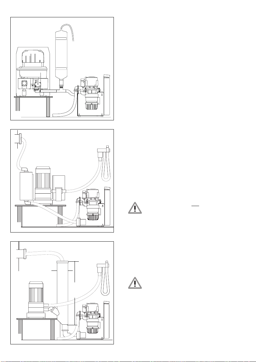
8.3 Combination Facilities
The Amalgam Separator AZ 50 can be
combined with the following suction machines:
VS 300
• AZ 50 combined with the Dürr Suction Unit.
VS 300
• AZ 50 combined with water ring pumps.
8.4 Planning a Pressure Equalising
Pipe or Air Demixer
To cater for proper pressure equalisation in
the suction system between the amalgam
separator and the suction unit, a pressure
6
PAL
equalising pipe or air demixer needs to be
mounted in conjunction with the following
combinations:
7112-017112-01
•
7112-01 - Pressure equalising pipe from
7112-017112-01
Dürr Dental - to be mounted in conjunction
with the Dürr Suction Unit VS 300!
7112-02 7112-02
•
7112-02 - Air demixers,
7112-02 7112-02
Dental must be mounted with a water ring
pump, e.g. Dental EZ!
notnot
not supplied by Dürr
notnot
8.5 Hose Material
In conjunction with the amalgam separator
use may only be made of flexible PVC spiral
hoses with integral spiral or equivalent hoses.
The following must not be used:
Hoses not resistant to dental
disinfectants and chemicals as well
as rubber hoses or solid PVC hoses
7
that are insufficiently flexible.
36
8
Dental EZ
10cm
100cm
8.6 Hose Laying
Hose laying
i.e. between the suction unit or water ring
pump and the AZ 50 must proceed observing
a slope. The hose length must not be allowed
to exceed 30 mm.
Hoses positioned
5050
50 must observe a slope.
5050
upstream or ahead of the AZ 50upstream or ahead of the AZ 50
upstream or ahead of the AZ 50,
upstream or ahead of the AZ 50upstream or ahead of the AZ 50
On the VS 300 the entrance to the
amalgam separator must not be
higher than the exit of the suction
machine, otherwise there will be a
risk of liquid and sediment flowing
back into the suction machine.
downstream or after the AZdownstream or after the AZ
downstream or after the AZ
downstream or after the AZdownstream or after the AZ
Page 13

8.7 Odour Trap
The drain on the AZ 50 must be connected via
an odour trap by the user.
9. INSTALLATION OF AZ 50
Integration of the Amalgam AZ 50 into
existing or new suction drawoff systems:
9.1 Fixing the AZ 50 in Place
• If mains connection proceeds via an
earthing-contact type socketearthing-contact type socket
earthing-contact type socket (wired to the
earthing-contact type socketearthing-contact type socket
equipment or surgery main switch) the
50 need not be fixed in position50 need not be fixed in position
50 need not be fixed in position.
50 need not be fixed in position50 need not be fixed in position
• Where
• Fix the amalgam separator in a suitable
fixed mains connectionfixed mains connection
fixed mains connection of the AZ 50
fixed mains connectionfixed mains connection
takes place on terminal strips via the
equipment or surgery main switch the
must be fixed in positionmust be fixed in position
must be fixed in position.
must be fixed in positionmust be fixed in position
Refer to point 10 “Electrical Connection” for
this.
directly next to or at a distance notdirectly next to or at a distance not
place
directly next to or at a distance not
directly next to or at a distance notdirectly next to or at a distance not
exceeding 30 cmexceeding 30 cm
exceeding 30 cm from the suction unit or
exceeding 30 cmexceeding 30 cm
water ring pump with a dowel and screw
connection made to a shelf, wall or angle
frame.
If the spacing distance between the
AZ 50 and the suction unit is too
great combined with failure to
ensure correct hose laying, there is
a risk of the secretion not being
conveyed as it should.
AZAZ
AZ
AZAZ
AZ 50AZ 50
AZ 50
AZ 50AZ 50
9.2 Fixing the Pressure Equalising
Pipe in Place
The pressure equalising pipe as supplied
needs to be mounted in the connecting hose
between the Dürr Suction Unit VS 300 and the
Amalgam Separator AZ 50.
37
Page 14

10. ELECTRICAL CONNECTION
Electrical connection must proceed via the
main switch of the treatment unit or the
surgery main switch.
The leads or cables to the machine
must be laid without any stress or
strain (strain relief clamps).
10.1 Mains Connection via EarthingContact Type Socket
Where the mains connection, 230V, proceeds
earthing-contact type socketearthing-contact type socket
via an
earthing-contact type socket, this must
earthing-contact type socketearthing-contact type socket
be wired to the equipment or surgery main
switch.
10.2 Fixed Mains Connection
In the case of fixed mains connection, 230V
connection proceeds on suitable terminals
behind the main switch of the treatment unit
via the equipment or surgery main switch.
Line cross section: 0.75 mm
2
10.3 Electrical Connection in AZ 50
Connection of the control contact on the
suction unit or water ring pump takes place on
the marked terminals inside the terminal box
of the AZ 50.
Connection of the contact in the hose
manifold, dental mouth-rinsing basin valve,
position selection valve and flushing system
(built into the treatment unit) proceeds via the
control cable.
1, 2 and 3 in terminal box of AZ 50.
,,
,
,,
38
Page 15

10.4 Display Module
The display module should be visible and
audible at all times. For that reason, it needs
to be mounted in a place where it can be
easily observed.
A display module is mounted to the AZ 50. If
the machine is located in a clearly visible
place in the surgery, no further display module
will be required.
If the separator is not located in the dental
surgery, an
mounted. Again, this should be located in a
place where it can be easily observed, e.g.
mounted to the treatment unit. Connection to
the AZ 50 proceeds via a 6-core cable and
distribution box.
additionaladditional
additional display module can be
additionaladditional
11. PUTTING INTO OPERATION
• Switch on equipment or surgery main
switch. As soon as the green LED lights up,
the AZ 50 will be ready for operation.
• Carry out functional check and also check
the connections for tightness.
11.1 Functional Check
• To perform this check, switch on the
equipment or surgery main switch. The
sensor will be heard to fall as it proceeds to
measure the filling level.
11.2 Visual Check
Check connections, hoses and AZ 50 for
tightness, sealing if necessary. For this
purpose, proceed to lift up the suction hose
and switch on the basin flushing system. This
starts up the AZ 50 and the liquid is transported
to the centrifuge drum from where it flows into
the drain.
11.3 Service Button
Press the service button (14, page 8) for at
least 2 sec. This serves to start up the
centrifuge motor which will be braked to a
standstill after approx. 30 sec.
11.4 Emergency Program
In the event of failure occurring on the AZ 50
for technical reasons, short-time operation of
the suction unit will be possible despite this
failure. In that case, the secretion drawn off by
suction from the patient’s mouth will continue
to be pumped into the AZ 50. The AZ 50 will
then act as a sediment separator but will need
to be repaired as quickly as possible.
39
Page 16

12. TIPS FOR TRACING FAULTS
Faults Possible Cause
1. No indication on display module,
separator not “READY FOR
OPERATION”
2. Yellow LED appears on display
module,
centrifuge motor fails to start up Fault
• Main switch on treatment unit or surgery main switch
not switched on.
• Cable fault or display module defective.
• Orange LED lights up, safety switch (11, page 30)
activated or winding burned out.
• Mains fuse defective.
• Motor jammed.
40
Page 17

Solution
• Switch main switch of treatment unit or surgery main switch to “ON” position.
• Replace cable or display module.
• Collecting vessel incorrectly inserted or safety switch defective; if necessary replace switch or
AZ 50.
• Centrifuge motor defective, remove any particles that may be present in the pump area or
centrifuge drum. Replace fuse.
• Check to ensure that the centrifuge motor is running properly, remove any particles that may be
present in the pump area or centrifuge drum.
41
Page 18

13. SERVICE-PROGRAMM
42
Page 19

FUNCTIONAL SEQUENCE
In order to be able to check whether the AZ 50
is working properly, a service program can be
activated. The various program steps are as
follows:
• To effect STARTUP press start button on
display module while simultaneously
switching the main switch to ON.
• Indicator Test:
Green, orange and yellow LEDs light up.
• Safety limit switch
Switching-on signal for AZ 50.
• Motor run.
• Sediment filling-level measurement.
• Output signal AZ 50 for suction unit:
Yellow LED lights up.
• Stop
Pressing the service button
continue the sequence of program steps.
Pressing the service button
repeat a program step. Startup of the service
program is indicated by an audible signal tone
in addition to the 3 LEDs.
13.1 Start
To start the service program, keep the service
button pressed down on the display module
and switch on the voltage supply to the AZ 50.
As soon as the signal tone is heard, let go of
the service button.
13.2 Indicator Test
During the indicator test all three LEDs light
up in addition to a signal tone being heard.
13.3 Safety Switch
During this program step various input signals
undergo evaluation and are visible on the
display module. In addition to LED indication a
signal tone will sound.
In the normal state, the LEDs are switched off.
twicetwice
twice serves to
twicetwice
onceonce
once serves to
onceonce
13.4 Motor Running and Braking
Action
Starting up this program step automatically
activates the motor and causes the motor to
slow down after approx. 12 sec. This test step
can be repeated by pressing the service
button once only. In that case the motor
running action must be switched off by
pressing the service button once more.
During the program step Motor Running and
Braking Action the various speed ranges are
represented on the display module by
different LEDs.
The no-load speed is set to 2800 RPM.
13.5 Sediment Scanning
This program step serves to check the
sediment probe for proper functioning.
Each time the service button is pressed, the
sediment probe will descend. If use is made
test vesseltest vessel
of a
test vessel, the various filling levels can
test vesseltest vessel
be scanned and rendered visible on the
display module.
13.6 Output Signals
In the course of this program step, various
output signals are activated simultaneously
which can then be measured as a voltage on
different connectors.
The specified voltages are optimum values.
• Yellow LED on display module of AZ 50.
• Control signal for suction unit X 6 contact 1
& 2 has connected through (relay
responded).
13.7 Stop
Quit the service program (stop=display off) by
switching off the voltage supply on the
treatment unit.
Pressing the service button twice at the end of
the program will return you to the beginning of
the program again.
• Open collecting vessel, safety switch is
actuated => orange LED lights up.
• Remove suction hose for hose
manifold => green LED lights up.
43
Page 20

14. TRANSPORT OF THE AZ 50
Should it be necessary to move the Amalgam
Separator AZ 50 to a different place, the
following action needs to be taken prior to
transporting the unit:
• Clean and disinfect the suction system.
• Remove the contaminated collecting vessel
and replace by a new collecting vessel.
• Do not turn the AZ 50 upside down as
otherwise dirt will enter the centrifuge drum
and cause congestion.
44
Page 21

USE
16
15. OPERATION
15
15.1 Ready for Operation State
14
13
Green LED (16) lights up.
15.2 Amalgam Collecting Vessel
95% full
Green LED (16) lights up.
and
yellow LED (13) lights up.
and
hooter sounds.
• As soon as the 95% filling level
the hooter can be switched off by pressing
pushbutton (14). Afterwards the
green LED (16) - Amalgam Separator
“Ready for Operation” will light up.
1
2
• The yellow LED
of the necessity to replace the amalgam
collecting vessel.
The amalgam collecting vessel needs
to be replaced as soon as a filling
level of 95% is attained.
Refer to point 17 for this.
(13) lights up as a reminder
is attained,
15.3 Amalgam Collecting Vessel
100% full
Yellow LED (13) lights up.
and
orange LED (15) starts flashing.
and
hooter sounds.
• Once the 100% filling level
will no longer be possible to switch off the
hooter by pressing pushbutton (14).
• The AZ 50 will not be “Ready for Operati-
on” again until the amalgam collecting
vessel has been replaced.
is attained, it
45
Page 22

15.4 Fault
Orange LED (15) starts flashing
and
hooter sounds
• The hooter can be silenced by briefly
pressing pushbutton (14).
• If pushbutton (14 ) is held down for
than 2 seconds
be started up once more.
• Green LED (16) lights up denoting “Ready
for Operation”.
• If, in response to pressing pushbutton (14)
several times, a fault alarm is registered
each time, this is a sign of a technical defect
having occurred.
Call technician.
For hints to assist the dental
technician in locating the fault,
please refer to point 12.
the amalgam separator can
longer
16. CLEANING AND
DISINFECTION
A material-compatible, non-foaming
disinfectant for suction systems is prescribed
for cleaning and disinfecting the entire suction
system including the amalgam separator and
the water volume linked to the collecting
vessel.
We recommend cleaning and
disinfection of the suction system
twice a day.
Further information will be gathered
from the Instructions for Disinfecting
and Cleaning Suction Systems, Part
no. 9000-605-10.
17. REPLACING THE AMALGAM
COLLECTING VESSEL
17.1 BEFORE replacing the amalgam
collecting vessel, please observe
the following:
• Replace the amalgam collecting vessel in
the MORNING!
We recommend that the amalgam collecting
vessel always be replaced in the morning
prior to the commencement of work. This
serves to prevent liquid from dripping out of
the drum during replacement.
17.2 Replacement of Amalgam
Collecting Vessel
• Switch off the main switch of the treatment
unit.
If the collecting vessel is unscrewed
without the treatment unit having been
switched off, the orange LED will start
flashing and the hooter will sound.
• Remove the empty collecting vessel from
the carton and screw off the lid.
To reduce the risk of infection, we
recommend that liquid-proof gloves be
worn while replacing the collecting
vessel.
• Hold the collecting vessel attached to the
AZ 50 from underneath, turn in direction of
arrow and remove downwards.
• Cut the disinfectant bag open at one of the
corners and pour the contents into the full
collecting vessel.
The disinfectant causes acid burns.
If coming into contact with the eyes,
rinse thoroughly with water and
seek medical advice. If coming into
contact with the skin, wash off with
soap and water.
• Seal the lid on the full
paying careful attention to the markings on
the lid. If the lid is properly sealed, these
markings should face one another.
• Place the sealed collecting vessel in the
transport carton, seal and secure with
adhesive tape to prevent accidental
opening.
• Insert the empty collecting vessel in the AZ
50 from underneath and turn in the direction
of the arrow as far as it will go.
The AZ 50 is now “Ready for Operation”
once more.
collecting vessel,
17.3 Disposal of Amalgam Collecting
Vessel
Write the name and address of the recycling
enterprise on the transport carton and send to
authorised disposal company by post or by
other means.
Relevant national regulations must be
observed.
46
Page 23

18. MAINTENANCE
• Depending on the volume accumulating, the
amalgam collecting vessel will need
16
replacing once or twice a year.
15
14
13
To reduce the risk of infection, we
recommend that liquid-proof gloves be
worn while replacing the collecting
vessel.
18.1 Annual Testing of Indicators on
Display Module
This test must be carried out by suitably
trained personnel.
Accessories needed for testing
1 Test vessel
••
• Testing the green LED (16)
••
After the main switch is switched on, the
green LED should light up denoting that the
machine is “Ready for Operation”.
••
• Testing the orange LED (15) and
••
pushbutton (14)
- Remove collecting vessel. The orange LED
(15) should now light up and the hooter
should sound as well.
Pressing pushbutton (14) should silence
the hooter, while the orange LED will
continue to flash.
To reduce the risk of infection, we
recommend that liquid-proof gloves be
worn while replacing the collecting vessel.
• Testing the yellow LED (13)
- Position main switch to OFF
- Remove collecting vessel, insert test
vessel, close and set to 100% filling level.
- Position main switch to ON
After sediment querying has been carried
out, the yellow LED should now light up, the
orange LED will respond by flashing and
the hooter will sound.
- Position main switch to OFF
- Remove test vessel.
- Insert collecting vessel (7) and close.
Remember to record the results of the test
in operating log book!
47
Page 24

18.2 Testing for Proper Working
Order - Every 5 Years
This test should be carried out by an inspector
every 5 years observing national statutory
regulations (in accordance with the General
Sewage Handling Regulations, Annex 50,
Dental Treatment).
Required tools and equipment:
1 Phillips screwdriver
1 Test vessel
1 Measuring cup
• Remove collecting vessel. During this
process the orange LED on the display
module should respond by flashing and the
hooter should sound as well. The hooter can
be silenced by pressing pushbutton (14,
page 23) on the display module.
• Insert test vessel.
• Press pushbutton (14) on the display
module and the green LED denoting
“READY FOR OPERATION” should light up
once more.
• Turn on dental mouth-rinsing basin and
draw off at least 200 ml water via suction
hose. Hook suction hose back in place.
• After the AZ 50 has switched off, remove the
test vessel and pour the water contained in
the vessel into a measuring cup.
If contents exceed 70 ml this denotes that
the AZ 50 is in proper working order.
An operating log book must be kept
by the user covering all maintenance
work. See “OPERATING LOG BOOK
FOR DÜRR AMALGAM SEPARATOR”,
Part no. 9000-605-72
18.3 Inspection of the Centrifugal
Pump - Every 2 Years
Part no. 7112-991-00. Test and clean,
replacing if necessary.
19. DISPOSAL OF THE MACHINE
Substances including heavy metals and
amalgam dust in the form of fillings that have
been drilled open are drawn off via the suction
hoses. To reduce heavy metal contamination in
sewage stemming from dental treatment
equipment, the waste water accumulating must
be disposed of observing the valid general
sewage handling regulations in force in the
country of use.
Components contaminated with amalgam,
such as strainers, filters and hoses, etc. must
likewise be disposed of in accordance with the
respective national regulations.
The AZ 50 can be disposed of in the normal
way.
The built-in control unit, electronics board and
electronic components must be disposed of as
electronic scrap.
48
 Loading...