

Page 1

INDEX
Important Information
1. Notes ...................................................... 30
1.1 CE - Labelling ................................. 30
1.2 Guidelines .......................................30
1.3 General Notes ................................. 30
1.4 General Safety Notes ..................... 30
1.5 Electrical Safety Notes ...................31
1.6 Warnings and Symbols..................31
2. Product Information ............................ 32
2.1 Correct Usage ................................ 32
2.2 Use other than that for the
intended purpose ........................... 32
2.3 Product description ........................ 32
3. Delivery Contents ................................. 33
3.1 Special Accessories ....................... 33
3.2 Disposable material ........................ 33
4. Technical Data ...................................... 34
5. Function ................................................ 36
6. Functional Description ....................... 37
6.1 Compressor .................................... 37
6.2 Control unit with pressure switch ... 37
Installation
7. Storage and
transport requirements ....................... 38
8. Requirements for Set-up .................... 39
8.1 Environmental Requirements ......... 39
8.2 Compressed Air Connection .........40
8.3 Electrical connection ....................... 41
8.4 Pressure switch check and setting42
8.5 Motor circuit breaker adjustment ... 42
8.6 Commissioning ............................... 43
8.7 Draining off condensed water .......43
9. Repairs and Maintenance ................... 44
9.1 Draining off condensed water .......44
9.2 Safety valve .................................... 44
9.3 Filter change ................................... 44
10. Circuit Diagram ..................................... 45
Use
11. Operation............................................... 47
11.1 Turning on the compressor ............ 47
12. Maintenance .......................................... 48
12.1Pressure reducer (accessory) ...... 48
12.2Adjusting the pressure reducer ....48
12.3 Draining off condensed water ....... 48
12.4Safety valve ....................................49
12.5 Filter change ................................... 49
13. Maintenance intervals - Operator /
Technician ............................................. 50
14. Decommissioning ................................ 50
Trouble-shooting
15. Tips for Technicians ............................ 51
16. Tips for Operators ................................ 53
Disposal
17. Disposal of appliance .......................... 54
Parts list
Compressor 51../52.. ............................. 56-62
29
Page 2

IMPORTANT INFORMATION
1. NOTES
1.1 CE - Labelling
CE-Symbol of conformity. This symbol of
conformity guarantees that this appliance
conforms to the relevant safety guidelines of
the European Union.
1.2 Guidelines
This appliance conforms to the following
safety guidelines:
• Machine guidelines 98/37EG, with
amendments.
• Electro-magnetic Compatibility 89/336/
EWG, with amendments.
• Low-voltage guidelines 73/23/EWG, with
amendments.
• Pressure vessel guidelines 87/404/EWG.
1.3 General Notes
• These Installation and Operating
Instructions form an integral part of the unit.
They must be kept close to the unit and in
readiness whenever required. Precise
observance of these instructions is a precondition for use of the unit for the intended
purpose and for its correct operation.
Die Montage- und Gebrauchsanweisung
sollte gegebenenfalls an Nachfolger weiter
gegeben werden.
• Safety for the operator as well as troublefree operation of the unit are only ensured if
use is made of original equipment parts.
Moreover, use may only be made of those
accessories that are specified in the
technical documentation or that have been
expressly approved and released by Dürr
Dental for the intended purpose.
Dürr Dental cannot guarantee for the safety
or proper functioning of this unit in the case
where parts or accessories are used which
are not supplied by Dürr Dental.
• The guarantee does not cover damage to
caused to this unit where parts or
accessories are used which are not
supplied by Dürr Dental.
30
• The guarantee is valid for 1 year
commencing from the date of delivery. Any
work performed under guarantee will
neither extend nor renew the guarantee.
• Dürr Dental only regard themselves as
being responsible for the equipment with
regard to safety, reliability and proper
functioning if assembly, resettings,
changes or modifications, extensions and
repairs have been carried out by Dürr
Dental or an agency authorised by Dürr
Dental and if the equipment is used in
conformity with the Installation and
Operating Instructions.
• These Installation and Operating
Instructions conform to the relevant version
of the equipment and the underlying safety
standards valid at the time of going to
press. All switches, processes, trade
marks, software programs and appliances
named in this document are registered
names.
• Any reprinting of the technical
documentation, in whole or in part, is
subject to prior approval of Dürr Dental
being given in writing.
1.4 General Safety Notes
This compressor has been designed and
constructed by Dürr Dental so that correct
usage of the appliance is virtually free of any
possible injury or danger. In spite of this, we
feel it is our duty to mention the following
safety measures in order to prevent any
possible danger to all personnel.
• When using this compressor all local and
relevant regulations must be observed! In
the interests of trouble-free operation the
operator is responsible for observing
these regulations.
• Retain the packaging for possible return of
the product to the manufacturers. Ensure
that the packaging is kept out of the reach
of children. Only the original packaging
provides adequate protection during
transport of the unit.
Should return of the product to the
manufacturers be necessary during the
guarantee period, Dürr Dental accepts no
responsibility for damage occurring during
transport where the original packaging
was not used!
Page 3
• Before every use the operator must check
the functional safety and the condition of
the appliance.
• The operator must be knowledgeable in the
operation of the appliance.
• The product is not designed to be used in
medical treatment areas where there exists
the danger of explosion. Areas where
explosions could occur are those where
flammable anesthetic material, skin
cleansers, oxygen and skin disinfectants
are present. This appliance is not to be
used in areas where the atmosphere could
cause fire.
1.5 Electrical Safety Notes
• The compressor may only be connected to
an earthed safety socket or CEE-socket,
depending on model of compressor.
• Before connecting the appliance to the
power supply check that the electrical
current and the frequency of the device as
described on the appliance are compatible
with that of the power supply.
• Check the appliance and the power supply
cables for possible damage before
switching on. Damaged cables, plugs and
sockets must be replaced before use.
• In danger situations or in cases of technical
defect immediately separate from the
power supply (unplug).
• In cases of repairs and/or maintenance the
compressor must be disconnected from
the mains supply, and the air supply hoses
as well as the pressurized container must
be depressurized.
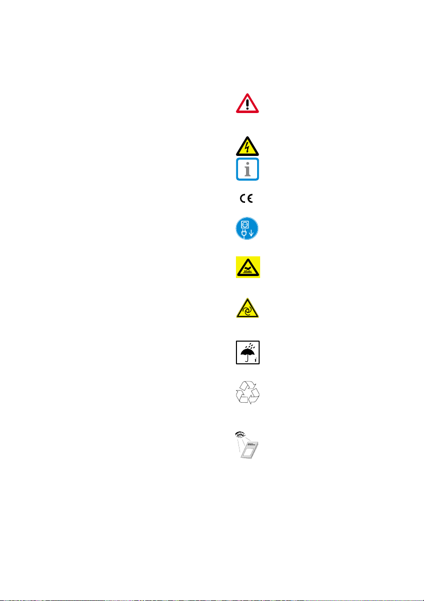
1.6 Warnings and Symbols
In the Installation and Operating Instructions
use is made of the following terms or
symbols to denote information of special
importance:
Information and/or mandatory
regulations or prohibitions for the
prevention of personal injury or
substantial property damage.
Warning! High voltage.
Special information regarding the
economical use of the equipment and
other information.
CE-Labeling
Disconnect from mains supply.
Warning! Hot surface.
Warning!
Compressor starts automatically.
Check environment. The appliance
should not be used in wet or damp
conditions.
Recycling
Observe installation and operating
instructions!
31
Page 4

2. PRODUCT INFORMATION
2.1 Correct Usage
This compressor is only designed for
providing compressed air for dental units or
similar applications.
Mounting in medical treatment units:
During the development and production of
this surgery compressor all requirements
concerning medical products were taken into
consideration wherever possible. Thus this
appliance can be mounted in medical
treatment units.
Where this appliance is mounted in medical
treatment units, then the requirements of
guidelines 93/42 EWG must be observed on
installation and operation.
2.2 Use other than that for the
intended purpose
The compressed air provided by
this unit is not suitable for use in
breathing apparatus or similar
facilities without the addition of
special filters, such as those used
in surgical areas.
• The compressors are designed for use in
dry, ventilated rooms with an ambient
temperature of +10 to +40 °C.
• Do not set up the compressor in the rain.
The machine must not be used in wet or
damp conditions. Furthermore, operation in
the vicinity of gases or flammable fluids is
forbidden.
• Before installing the compressor in medical
facilities it must be checked that that the
available material is designed to satisfy the
requirements of the purpose for which is
intended. Please observe the technical
data.
• Any classification and conformity evaluation
should be carried out by the manufacturer
of the end product.
• Any other use or use beyond what is
specified is deemed to be not for the
intended purpose. The manufacturer
accepts no liability for damage resulting
therefrom. All risk is borne solely by the
user.
2.3 Product description
The Dürr Compressor 51../52.. provides an
oil-free, dry and filtered pressurized air, for
use in medical units.
32
Page 5

3. DELIVERY CONTENTS
Compressor with / out Dry Air System
(DAS):
Compressor accessories .......... 5410-002-50
nstallation and
operating instruction ............. 9000-610-01/01
Compressor with Dry Air System (DAS)
only:
Collection tank ............................ 3413-001-00
Operating instructions DAS ...... 9000-610-34
3.1 Special Accessories
The following parts are not standard and
must be ordered separately.
Pressure reducer ....................... 3410-008-00
Wooden cabinet ......................... 5110-500-00
Dry Air System,
upgrade set ................................ 1640-500-52
3.2 Disposable material
Filter set compressor .................. 0832-982-00
Filter set DAS ............................... 1610-121-00
Sterile filter DAS ........................... 1640-981-00
33
Page 6
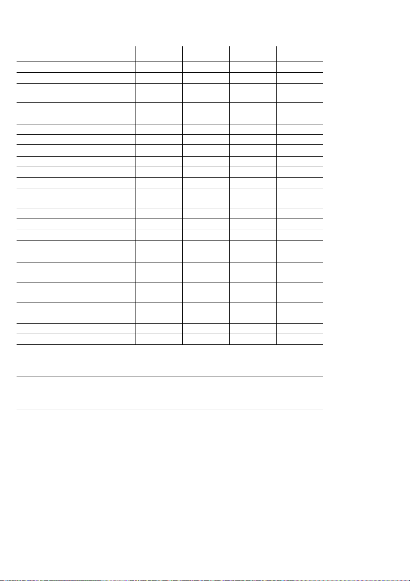
4. TECHNICAL DATA
Model 5110-01 5111-01 5120-51 5121-51
Voltage V 230/1~ 230/1~ 400/3~ 400/3~
Frequency Hz 50 50 50 50
Current consumption
at 7 bar A 3,8 3,8 1,5 1,5
Motor circuit
breaking set at A 4,2 4,2 1,6 1,6
Power rating kW 0,68 0,68 0,71 0,71
R.P.M. min
Mains fuse rating A16161010
Fuse type IP 44 IP 44 IP 44 IP 44
Noise level dB(A) 66 66 66 66
No. cylinders 1111
Flow rate
at 5 bar l/min 55 53 55 53
* Charge time min3333
Open/Shutoff pressure bar 5,5 – 7,5 5,5 – 7,5 5,5 – 7,5 5,5 – 7,5
Safety valve setting bar8888
Vessel volume l25252525
Duty cycle %ED 100 50 100 50
DAS - yes - yes
Filtration, filter
(0832-982-00) compr. µm 10 10 10 10
Filtration, fine filter
(1610-121-00) dry air µm - 3,5 - 3,5
Filtration, sterile filter
(1640-981-00) dry air µm - 0,01 - 0,01
Weight kg 39 48 39 48
Dimensions
Transport and storage conditions
Temperature
Relative humidity
Operating conditions
Temperature
Relative humidity
(H x L x D) cm 68 x 40 x 39 68 x 39 x 40 68 x 39 x 4068 x 40 x 48
-25 °C to +55 °C
10% to 90% (no condensation)
+10 °C to 40 °C
up
to 70%
-1
1400 1400 1400 1400
* Time taken for the compressor to reach the
shut-off pressure of 7.5 bar from start-up
pressure of 0 bar
34
Page 7
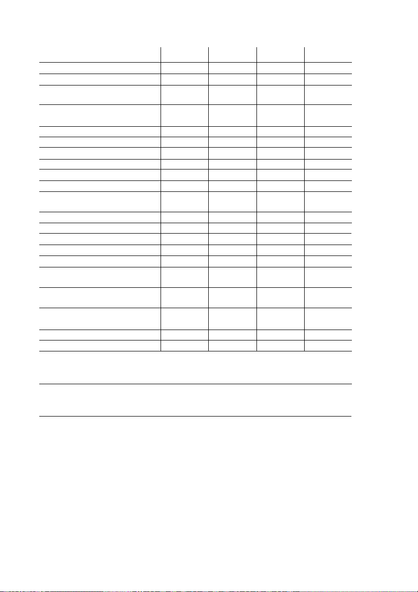
Model 5210-01 5211-01 5220-51 5221-51
Voltage V 230/1~ 230/1~ 400/3~ 400/3~
Frequency Hz 50 50 50 50
Current consumption
at 7 bar A 3,8 3,8 3,5 3,5
Motor circuit
breaking set at A 4,2 4,2 3,6 3,6
Power rating kW 0,68 0,68 1,5 1,5
R.P.M. min
Mains fuse rating A16161010
Fuse type IP 44 IP 44 IP 44 IP 44
Noise level dB(A) 69 69 69 69
No. cylinders 2333
Flow rate
at 5 bar l/min 115 110 155 110
* Charge time min 1,5 1,5 1,5 1,5
Open/Shutoff pressure bar 5,5 – 7,5 5,5 – 7,5 5,5 – 7,5 5,5 – 7,5
Safety valve setting bar8888
Vessel volume l25252525
Duty cycle %ED 100 50 100 50
DAS -ja-ja
Filtration, filter
(0832-982-00) compr. µm 10 10 10 10
Filtration, fine filter
(1610-121-00) dry air µm - 3,5 - 3,5
Filtration, sterile filter
(1640-981-00) dry air µm - 0,01 - 0,01
Weight kg 48 56 48 56
Dimensions
(H x L x D) cm 68 x 40 x 45 68 x 40 x 48 68 x 40 x 4568 x 40 x 48
Transport and storage conditions
Temperature
Relative humidity
-25 °C to +55 °C
10% to 90% (no condensation)
Operating conditions
Temperature
Relative humidity
+10 °C to 40 °C
up
to 70%
-1
1400 1400 1400 1400
* Time taken for the compressor to reach the
shut-off pressure of 7.5 bar from start-up
pressure of 0 bar
35
Page 8
5. FUNCTION
17 18
1
2
8
3
16
14
13
15
12
10
11
4
7
6
5
36
Page 9

6. FUNCTIONAL DESCRIPTION
6.1 Compressor
Atmospheric air is drawn into the cylinder
chamber via a suction filter (17). The piston
(18) in the cylinder then compresses this air.
The inlet/outlet valve cuts off one flow route
thereby forcing the air directly into the tank
(10) via the non-return valve.
Where a DAS is present (2), the
compressed air is led through the spiral
cooling pipe (3) to the dry air system (2). In
this way the air, warmed on compressing, is
now cooled whereby most of the water
present in the air is extracted as
condensated water. Each time the
compressor motor is sitched ioff this
condensated water is collected in the
collection tank (5). The partially dry air is then
fed through the drying agent (6), the
Sintermetallfilter (4) and the fine filter (1) as
dry and hygienic air into the compressor
chamber (10). The non-return valve (7)
ensures the compressed air cannot escape.
The compressor motor (11) continues to
provide compressed air until the pressure
switch (16) registers that the pressure
correct level has been achieved. (The actual
pressure can be read off the pressure
gauge (15).)
If the maximum relative humidity in the tank
(10) is exceeded, then the Polyamidband
Hygrostat (8) expands, whereby a valve is
opened and dry air from the tank flows in the
reverse direction towards the DAS (2).
During this phase the unit is regenerating.
This means that the humidity present in the
DAS is carried via the dry air to the collection
tank (5). This regeneration procedure
repeats irself until such time as the pre-set
relative humidity at the Hygrostat (8) is
reached.
6.2 Control unit with pressure switch
If a user appliance (turbine etc.) draws off
compressed air, the tank pressure drops. If
in the tank the pre-set minmum pressure as
set at the pressure switch (16) is reached,
then the compressor motor is activated.
When the pre-set maximum pressure is
reached, the compressor motor is switched
off.
The control unit is fitted with a pressure
gauge (15) which displays the tank
pressure. A safety valve (12) prevents the
maximumm pressure from being exceeded,
eg in case of a defect.
The control unit is also fitted with a
condensed water drain tap (13) and a shutoff valve (14).
37
Page 10

INSTALLATION
7. STORAGE AND TRANSPORT
REQUIREMENTS
The compressor is packed in a carton for
transport. This prevents any damage to the
appliance during transport. Always use the
original packing for the machine wherever
possible.
Transport the machine in an upright
position.
During storage and transport,
protect the appliance at all times from
damp, dirt and extremes of
temperature. Take special care to
avoid any electrical parts from
becoming wet.
The surgery compressor is ready for
immediate installation. If the appliance is in its
original packing it can be stored in a warm,
dry and dust-free room.
(see technical data)
Retain the original packing if at all
possible. If this is not possible
dispose of the packing in an
environmentally correct way. The
transport carton can be disposed of
as paper waste.
38
The compressor must be
transported in pressure-free state.
Before transport empty the
compressor and bleed the hoses.
Vor Before transport or storage any
condensated water in the pressure vessel
must be drained off. (See section 8.7
Draining condensed water off).
Page 11

8. REQUIREMENTS FOR SET-UP
Set-up and commissioning
should only be carried out by an
authorized technician.
Observe local rules and
regulations
8.1 Environmental Requirements
• The appliance should only be installed and
operated in a well-ventilated, dry and dustfree room.
• The compressor must be installed in a
position that allows the identification plate to
be easily visible at all times and where
accessible for repairs and maintenance.
• The appliance must be placed on a
smooth, flat and stable floor.
(Note compressor weight, see technical
data).
The air intake side and the
ventilation grille on motor side
must both be free and there must
be adequate distance from the
nearest walls (c. 20 centimeter).
The power cable and the air hoses
must not be bent or twisted.
As the compressor starts
operation automatically as soon
as pressure falls below a set
amount, a warning sign in
accordance with ISO 7000-0017
must be displayed warning of
automatic operation.
39
Page 12

The room temperature must not be allowed
to fall below 10 °C otherwise a trouble-free
operation of the control unit within the
machine cannot be guaranteed.
If room temperatures exceed 40 °C, additional ventilation must be provided by installing
a fan (see Fig. 1).
The compressor unit gives off about
70 % of its electrical energy as heat
energy causing the ambient
temperature to rise if ventilation is
inadequate.
The motor fan provides efficient cooling to
the motor. For this to happen the air intake
1
and output must be unhindered. In extreme
cases a separate ventilation system must be
installed, see Fig. 1.
Do not place any objects on or
against the compressor; by a
room temperature of c. 40 °C the
cylinder and cylinder heads can
warm up to over 110 °C.
Fire risk!
40
8.2 Tryckluftsanslutning
The compressor is fitted as standard with a
control unit consisting of:
Pressure switch (16), pressure gauge (15),
safety valve (12), shut-off valve (14) and
condensed water drainage tap (13).
16
15
12
14
13
20
2
In order to ensure a constant
pressure flow, a pressure reducer
(as accessory) is recommended.
The pressure connection is carried out at the
connector nozzle (20) or the pressure
reducer (as accessory).
• The flexible pressure hose LW10 should be
pushed onto the connector nozzle and
secured from slipping using a hose clip.
The use of a flexible hose between
the fixed air connection and the
compressor helps to prevent the
transmission of vibration and noise.
Page 13

8.3 Electrical connection
Electrical connections should only
be carried out by a qualified
electrician.
(with the exception of those models
delivered supplied with either a
standard EEC plug or a shockproof
domestic plug according to model)
The compressor is supplied with a standard
EEC plug in the 400 V configuration and with
a shockproof domestic plug on the 230 V
model. All local and national regulations
concerning electrical connections must be
observed.
Mains voltage and frequency must coincide
with those shown on the identification plate.
No cables should be laid on the
unit. The hot surface of the unit
will melt and destroy the cable
insulation.
If the unit is connected directly to the mains
power supply then a power off switch must
be located in the vicinity of the unit that has a
minimum 3 mm contact gap (e.g. fuse box).
If the unit is connected to the mains power
supply via a plug and socket then, for safety
reasons, the socket must be easily
accessible so that the unit can be
disconnected in dangerous situations.
The relevant circuit must be fitted with a fuse
of maximal 16 A.
Observe the correct turning
direction for the alternating
current compressor unit (400 V):
The direction is clearly indicated by
an arrow on the ventilator cover. If the
direction of rotation is incorrect, there
is danger of the compressor unit
overheating.
If the turning direction is incorrect,
disconnect the unit at the mains and swap
the polarity of the two pressure switch power
supply cables.
When connecting the appliance to
a different outlet, check direction
of rotation!
41
Page 14

8.4 Pressure switch check and setting
The pressure switch (16) is factory-set.
At 5.5 bar the motor is switched ON.
21
At 7.5 bar the motor is switched OFF.
If required, the working pressure of
the compressor can be altered at the
pressure switch.
To do this, first the shutoff pressure and then
the connecting pressure must be set using
22
the pressure difference (
Before removing the protective
23
cap on the pressure switch, the
appliance must be disconnected
from the mains.
∆∆
∆P).
∆∆
3
Adjust cut-off pressure P
adjusting screw (22). (In direction of arrow
(+) it increases and in direction of arrow (-)
decreases). The pressure difference itself is
not altered in this operation. Note maximum
pressure (8 bar) as set at safety valve. The
shut-off pressure must be at least 0.5 bar
below that of the safety valve, otherwise the
safety valve will open and the compressor
motor runs continuously as it never achieves
the shut off pressure.
Adjust pressure difference
connecting pressure and shutoff pressure at
the adjustment screw (23), by turning it
towards plus (+) or minus (-).
using the
∆∆
∆P
between
∆∆
42
The tank must be under pressure when this
adjustment is carried out.
8.5 Motor circuit breaker adjustment
The motor circuit breaker (21) has been
factory-set. This value should be checked
during installation.
The motor circuit breaker is situated under
the pressure switch cover (16).
(See section 4. Technical Data).
• Measure max. current (value shortly before
shut off pressure is reached).
• Increase motor circuit breaker by adjusting
screw (21) approx. 0.3 A.
Page 15

8.6 Commissioning
• Check all compressed air connections.
• The unit must be connected to the power
16
supply correctly.
• Check that air filters are fitted correctly.
• Turn compressor at switch (16) to on.
(Position ‘I’)
• Check for abnormal noises from unit on
first use.
• For 400 V - compressors check rotation of
motor.
• Check on and shut-off pressures of the
compressor. (Approx.5.5 and 7.5 bar).
4
• Check safety valve for correct function,
(see 9.2 Safety valve).
8.7 Draining off condensed water
During transport condensated water may
accumulate in the tank due to temperature
differnces. Each time a compressor is set
up, first drain off the condensated water –
even from those compressors fitted with
DAS.
Proceed as follows:
• With the compressor switched on, and
maximum tank pressure, open the
condensated water drain tap (13) as far as
possible.
13
• Wait for the condensated water to be
blown completely out of the tank.
5
• Close the drain tap once more.
43
Page 16

9. REPAIRS AND MAINTENANCE
Repairs and maintenance should
only be carried out by a qualified
and authorized technician.
Only use parts and accessories
approved by the manufacturer.
Before all repairs and maintenance
the compressor must be switched
off and disconnected from power
supply (disconnect at mains).
The compressor surfaces are hot.
Let the compressor cool before all
repairs and maintenance.
9.1 Draining off condensed water
See 8.7.
9.2 Safety valve
The safety valve is set to 8 ba
manufacturer and then tested and stamped.
It may not be readjusted!
The safety valve must be checked for
correct functioning every six months.
To do this, open the knurled screw (12) at
12
max. tank pressure until air escapes from
the safety valve. Briefly allow air to blow
freely through the safety valve. Retighten the
knurled screw.
rr
r by the
rr
44
6
9.3 Filter change
The filter replacement interval will largely
depend on the extent of dust in the air.
Under normal conditions the filter needs
changing once a year.
See Installation Instructions
9000-416-016
Filter order numbers:
Compressor
Filter set ....................................... 0832-982-00
Dry Air System
Fine filter ...................................... 1610-121-00
Sterile filter ..................................... 1640-981-0
Page 17

10. CIRCUIT DIAGRAM
10.1 Version in 230 V 1~
Geräteliste
Q1 Pressure switch
X1 Power supply 230 V 50 Hz
M1 Compressor motor
Y1 Solenoid valve
(only for compressors without DAS)
M2 Ventilator
(only with anti-noise cover)
45
Page 18

10.2 Version in 400 V 3~
Parts list
Q1 Pressure switch
X1 Power supply 3/N/PE AC 400V 50Hz
M1 Compressor motor
Y1 Solenoid valve
(only for compressors without DAS)
M2 Ventilator
(only with anti-noise cover)
46
Page 19

USE
11. OPERATION
Operation of the compressor is relatively
easy and for the most part automatic.
In case of any danger disconnect
power supply (disconnect from
mains).
The compressor surfaces get hot.
Touching the surfaces could lead
to burns.
Automatic start-up. If the pressure
in the tank falls below a certain
level the motor starts and
continues to provide compressed
air until the maximum pressure is
16
7
reached.
11.1 Turning on the compressor
The compressor is switched on by turning
the handwheel on the control unit (16) to
position ‘I’. The motor starts and the
compressor fills to the maximum. On
reaching the shut-off level the motor stops.
The maximum permitted operating pressure
must not be exceeded. The maximum
permitted operating pressure is indicated on
the pressure gauge with a red line.
If the maximum permitted operating
pressure is exceeded, the compressor
motor must be disconnected from the power
supply (unplug at mains socket). Inform the
technician responsible.
47
Page 20

12. MAINTENANCE
In order to check that the compressor is
functioning absolutely correctly, the following
30
maintenance steps should be carried out
regularly.
12.1 Pressure reducer (accessory)
The fitting of a pressure reducer is strongly
recommended. (vor den Verbraucher)
The pressure reducer regulates the
pressure flow to achieve the desired
operating pressure. The pressure reducer is
mounted on the pressure switch.
31
8
12.2 Adjusting the pressure reducer
To adjust the pressure rate, operate the
nozzle, turbine, etc., lift up the adjusting ring
(30) and turn in the direction of the arrow +
(increase flow rate) or in the direction of the
arrow - (decrease flow rate), until the desired
flow rate is displayed. When finished replace
the adjusting ring, until it clicks gently in
place and the pressure reducer is protected
from unintentional adjustment. The desired
flow rate is now set. It can be read on the
pressure gauge (31).
For correct flow rates, see the
manufacturer’s operating instructions (e.g.
turbine etc.).
48
12.3 Draining off condensed water
Condensated water is removed automatically
in compressors fitted with a dry air system.
For compressors without DAS the
condensated water must be drained off at
least once a month!
In countries with high air humidity water
must be drained off daily!
Proceed as follows:
• With the compressor switched on, and
maximum tank pressure, open the
condensated water drain tap (13) as far as
possible.
13
• Wait for the condensated water to be
blown completely out of the tank.
9
• Close the drain tap once more.
Page 21

10
12.4 Safety valve
The safety valve is adjusted to 8 bar by the
manufacturer and then tested and stamped.
It may not be readjusted!
The safety valve must be checked for
correct functioning every six months.
To do this, open the knurled screw (12) at
max. tank pressure until air escapes from
the safety valve. Briefly allow air to blow
freely through the safety valve. Retighten the
12
knurled screw (12).
12.5 Filter change
17
The filter replacement interval will largely
depend on the extent of dust in the air.
Under normal conditions the filter needs
changing once a year.
11
1
35
See Installation Instructions
9000-461-016.
• Changing the suction filter (17).
Pull out the filter unit by the cap. Change
the complete filter unit.
• Changing the fine filter (1) of the DAS.
Unscrew cover (35). Pull out the fine filter
(1) and place new filter in position. Replace
cover.
Filter order numbers:
Compressor
Filter set ....................................... 0832-982-00
Dry Air System
Fine filter ...................................... 1610-121-00
Sterile filter ................................... 1640-981-00
49
Page 22

13. MAINTENANCE INTERVALS - OPERATOR / TECHNICIAN
Maintenance procedure Section Interval
Adjust pressure reducer 12.2 yearly
Drain condensated water *) 12.3 monthly
Check safety valve 12.4 every six month
Filter change 12.5 yearly
*) Only for non-DAS appliances.
In countries with high air humidity water must be drained off daily!
daily
14. DECOMMISSIONING
If the compressor is not going to be used for
a long period of time, it is recommended
draining the condensated water from the
tank. Allow the compressor to run for c. 10
minutes with the condensated water drain
tap (13) open. Then switch off at the main
switch, close the drainage tap and
disconnect from the mains.
50
13
12
Page 23

TROUBLE-SHOOTING
15. TIPS FOR TECHNICIANS
The following list of possible problem causes is designed for use by qualified
technicians. Repairs must only be carried out by qualified personnel.
Problem Solution
does not switch
on.
Probable cause
• No power.1. Compressor
• Pressure switch not on.
• Current higher than nominal
rating.
• Current continuously equal to
nominal rating.
• Ventilating valve defect, unit
runs with back pressure (nonDAS compressors only)
• Check mains fuse, if necessary
reset circuit breaker; if fuse is
blown, replace it. Check mains
current.
• Connect pressure switch and
wait 30 seconds. If the pressure
switch remains connected
briefly and then switches the
motor off, check the power
consumption: for all three
phases if three-phase and for
one phase if AC.
• Undervoltage: measure voltage,
call an electrician if necessary.
Capacitor defective (230 V 1~):
Check capacitor, replace if
necessary.
• Unit blocked mechanically,
piston seized (motor circuit
breaker triggered): pull out
mains plug, remove cover from
crank housing of overheated
compressor and turn fan wheel.
In the event of this not being
possible, replace piston and
cylinder, or entire unit.
• Motor circuit breaker set too low
(3~ only): measure current.
Adjust motor circuit breaker
accordingly (0.3 A higher than
current measured).
Motor circuit breaker defective:
Check motor circuit breaker and
replace if necessary.
• Check to ensure that ventilating
valve opens after unit is
switched on. Remove blockage
or replace.
51
Page 24

Probable causeProblem Solution
2. Compressor fails
to switch off.
3. Compressor
switches on
intermittently
without any air
being drawn off
by user.
4. Excessive
compressor
noise (e.g.
knocking
sound).
• Defective plate valve (inlet and/
or outlet valve) between
cylinder head and cylinder.
• Air escapes at ventilating valve
(non-DAS compressors only).
• Air blows through the DAS into
the collection tank.
• Leakage in compressed air
system
• Compressor capacity too low;
excessive air drawn off per
workstation, approx. 50 l/min.
• Worn piston compression seal.
• Air escaping down through dry
air system.
• Air escaping at non-return
valve.
• Leakage in connections.
• Damaged bearings
• Dismantle cylinder head and
install new plate valve.
• Check ventilating valve. (The
valve is open when power is off)
• Check dry air system control
head.
• Open shut-off valve and subject
tubes to pressure. Use spray to
find leak if necessary. Seal leak.
• Determine air requirements,
replace with larger compressor
if necessary.
• Replace piston and cylinder, or
entire unit.
• Dry air system is in
regeneration phase, air humidity
in tank is being reduced.
• Check non-return valve for air
leaks. Clean or replace nonreturn valve.
• Locate leak and seal.
• Check motor shaft bearings and
crankshaft bearings, replace if
necessary.
5 Supply
performance
loss, compressor
takes longer to
charge tank (For
charging
periods, see
Technical Data).
6. Water drips from
handset.
52
• Suction filter badly soiled.
• Defective plate valve (inlet and/
or outlet valve).
• Worn piston compression seal.
• Condensated water im tank.
• Suction filter should be replaced
at least once a year. Never
clean the filter with petrol or oil!
• Dismantle cylinder head and
install new plate valve.
• Replace piston and cylinder, or
entire unit.
• The condensed water must be
drained off at least once a
month. Or daily in tropical
zones or locations with high air
humidity.
Observe ambient temperature
of the compressor, (refer to the
requirements in the set-up
instructions.
Page 25

16. TIPS FOR OPERATORS
Probable causeProblem Solution
1. Compressor
does not switch
on.
2. Compressor fails
to switch off.
3. Compressor
switches on
intermittently
without any air
being drawn off
by user.
4. Excessive
compressor
noise (e.g.
knocking
sound).
• No power.
• Pressure switch not on.
• Compressor capacity too low;
excessive air drawn off per
workstation, approx. 50 l/min.
• Air escaping down through dry
air system.
• Air escaping at non-return
valve.
• Leakage in connections.
• Damaged bearings.
• Check mains fuse, if necessary
reset circuit breaker; if fuse is
blown, replace it. Check mains
current.
• Connect pressure switch and
wait 30 seconds.
• Contact your technician.
• Determine air requirements,
replace with larger compressor
if necessary.
• Contact your technician.
• Dry air system is in
regeneration phase, air humidity
in tank is being reduced.
• Check non-return valve for air
leaks.
• Locate leak and seal.
• Contact your technician.
• Contact your technician.
performance
loss, compressor
takes longer to
charge tank (For
charging
periods, see
Technical Data).
6. Water drips from
handset.
• Suction filter badly soiled.5 Supply
• Condensated water im tank.
• Suction filter should be replaced
at least once a year. Never
clean the filter with petrol or oil!
• The condensed water must be
drained off at least once a
month. Or daily in tropical
zones or locations with high air
humidity. Observe ambient
temperature of the compressor,
(refer to the requirements in the
set-up instructions).
53
Page 26

DISPOSAL
17. DISPOSAL OF APPLIANCE
• Unplug the unit
• Drain the compressor tank of air by
opening the condensated water tap.
(See 8.7 Draining off condensated water)
• Dispose of the compressor according to
local regulations concerning waste material.
54
Page 27

55
 Loading...