

Page 1
®
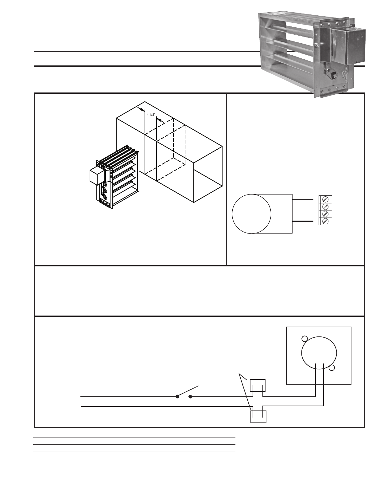
(M1) Common
(M2) Hot
(M4) Open
(M6) Close
1
2
4
6
DuroZone
INSTALLATION INSTRUCTIONS
MMB SERIES MULTI-BLADE DAMPER
SPRING RETURN MID-TORQUE MOTOR
INSTALLATION IN DUCT
1. Cut 4 1/8” wide slot into side of sheet metal duct.
2. Slide damper into duct work.
3. Secure by screwing the damper into the ductwork.
(Screws Provided)
MOTOR LEAD IDENTIFICATION
Yellow and Orange leads: 24 volt input AC Only
- IMPORTANT -
This motor is designed for use with 24 Volt VAC power source.
- WIRE ACCORDING TO LOCAL CODE -
TYPICAL WIRING
To Control Panel Part# 35226 (SMZ2SW)
35227 (SMZ3SW) /35229 (SMZAC)
35235(JTZHP) /35236 (ED3) /35237 (ED4)
Wiring diagram for a spring return damper
that without power is normally open
(spring open).
Control Panel
Terminal
Strip
NOTE: On SMZ Panels it is recommended
to leave the damper switches on the
control panel in the open position.
Spring Open Damper Motor Operation
Energizing the Yellow and Orange leads with 24 volts will close the damper.
Removing power from the Yellow and Orange leads will cause the damper
to return to a fully open position.
24 volts
Duro Dyne East • Bay Shore, NY 11706 • Phone: 631-249-9000 • Fax: 631-249-8346
Duro Dyne Midwest • Fairfield, OH 45011 • Phone: 513-870-6000 • Fax: 513-870-6005
Duro Dyne West • Santa Fe Springs, CA 90670 • Phone: 562-926-1774 • Fax: 562-926-5778
Duro Dyne Canada • Lachine • Quebec • Canada • Phone: 514-422-9760 • Fax: 514-636-0328
©2007 Duro Dyne Corporation
Printed in USA 06/2007
BI035403
Motor
Wire
Connectors
Switch or Relay
Contacts
Yellow
Orange
ALL DuroZone DAMPERS FEATURE:
• 3 year limited warranty • Controlled bypass •
Maintenance free operation • 100% factory testing • Screwless terminals • Custom dampers
and special controls are available on request.
Page 2
®
DuroZone
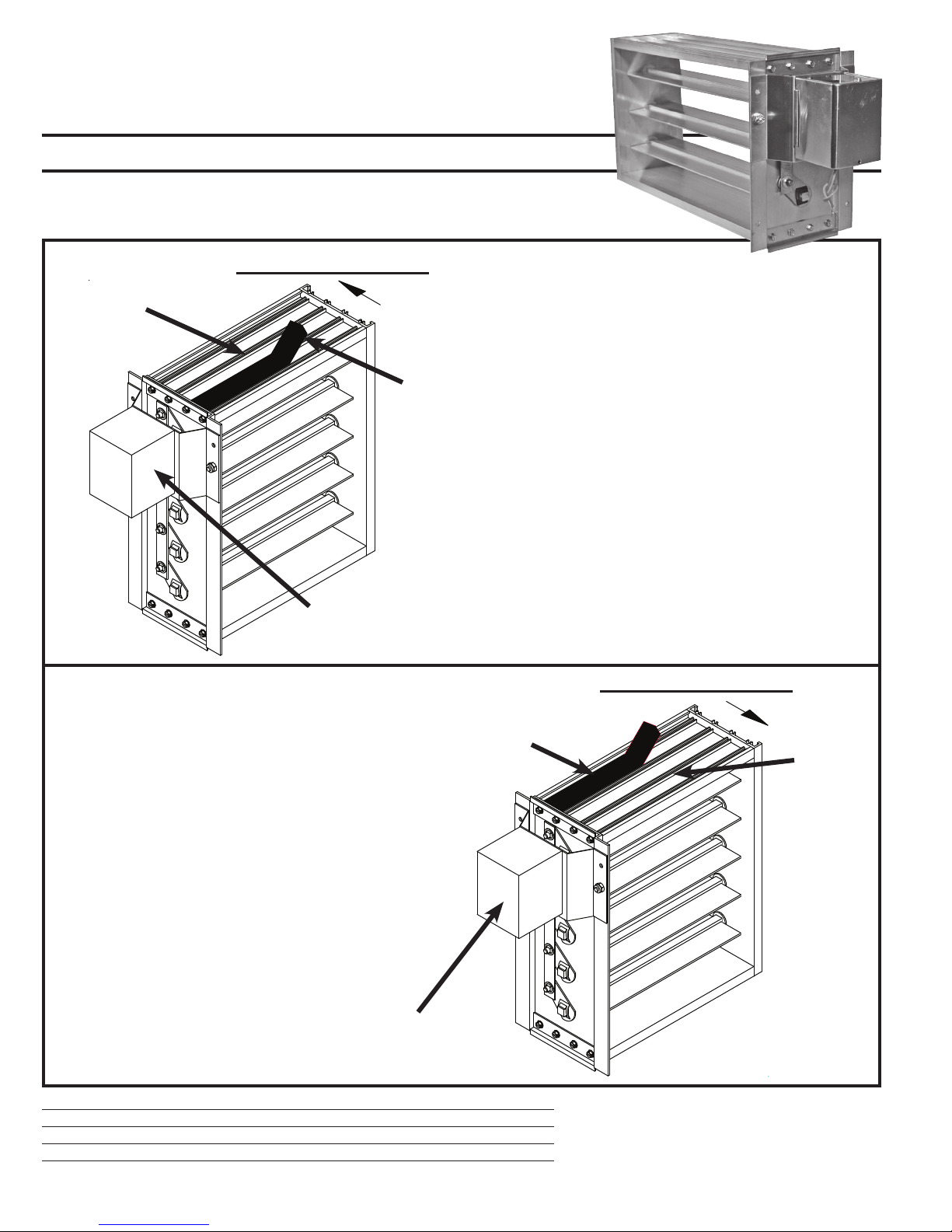
GASKET INSTALLATION INSTRUCTIONS
MMB SERIES MULTI-BLADE DAMPER
SPRING RETURN MID-TORQUE MOTOR
Direction of Air Flow
Ribs
Motor may vary
(Hi-torq or Mid-Torq)
Note the direction of the air-flow when
securing the gasket to the frame.
Gasket
Note the direction of the air-flow when
securing the gasket to the frame.
Gasket must be placed at the leading
face of the frame between the two end
ribs as shown.
Direction of Air Flow
Gasket
Ribs
Gasket must be placed at the leading
face of the frame between the two end
ribs as shown.
Motor may vary
(Hi-torq or Mid-Torq)
Duro Dyne East • Bay Shore, NY 11706 • Phone: 631-249-9000 • Fax: 631-249-8346
Duro Dyne Midwest • Fairfield, OH 45011 • Phone: 513-870-6000 • Fax: 513-870-6005
Duro Dyne West • Santa Fe Springs, CA 90670 • Phone: 562-926-1774 • Fax: 562-926-5778
Duro Dyne Canada • Lachine • Quebec • Canada • Phone: 514-422-9760 • Fax: 514-636-0328
©2007 Duro Dyne Corporation
Printed in USA 06/2007
BI035403
ALL DuroZone DAMPERS FEATURE:
• 3 year limited warranty • Controlled bypass •
Maintenance free operation • 100% factory testing • Screwless terminals • Custom dampers
and special controls are available on request.
 Loading...