

Page 1

WWW.DUROPRO.COM
Page 2
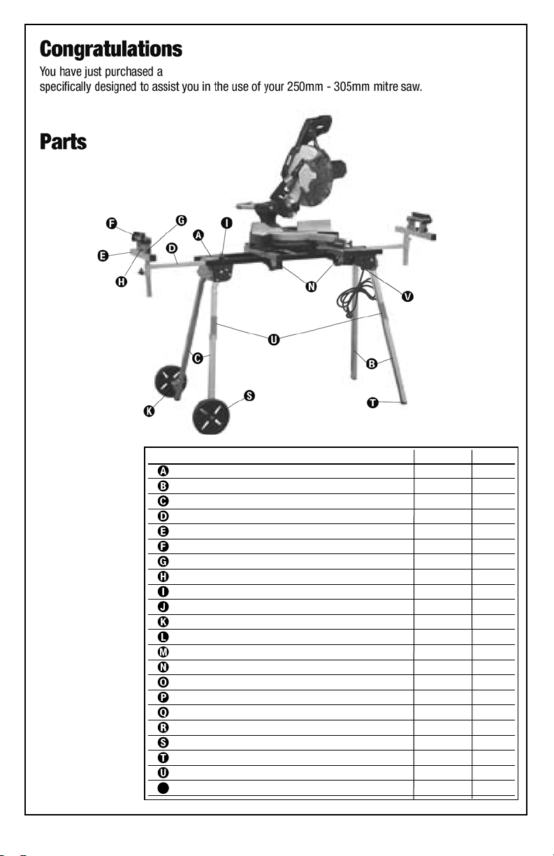
ytQ .oN traP noitpircseD
1 0013 emarF poT
2 1013 geL thgiartS
2 2013 geL devruC
2 3013 troppuS reggirtuO
2 4013 ylbmessA ”T“ troppuS
Roller Support with Flip-Stops K103 2
Roller Support Height Adjustment Knobs G115 4
Roller Support Adjustment Knob G112 2
4 5013 bonK tnioP-3
1 R6013 tekcarB elxA thgiR
1 L6013 tekcarB elxA tfeL
4 105D mm54 x 6M – tloB elxA
4 205D 6M – tuN elxA
Quick-Attach Machine Mounts 3042 2
Carriage Bolts – M8 x 63mm D503 4
4 405D 8M – srehsaW
4 505D 8M – rehsaW kcoL
4 605D 8M – tuN
2 7013 sleehW "8
4 025G sgulP geL
2 8013 stroppuS kcotS
1 9013 retneC rewoP teltuO-3
Congratulations
You have just purchased a Portamate PM5000 Heavy Duty Mitre Saw Stand. This product has been
specifically designed to assist you in the use of your 10-12" mitre saw.
Parts
Duropro PM6300 Heavy Duty Mitre Saw Stand. This product has been
V 2-Outlet Power Centre 3109 1
2
Page 3
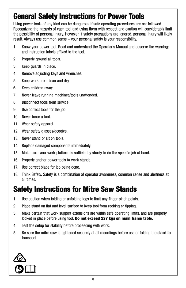
Safety Description of Symbols
Conforms to relevant standards for electrical safety and electromagnetic
Read these instructions for use carefully.
compatibility.
3
Page 4
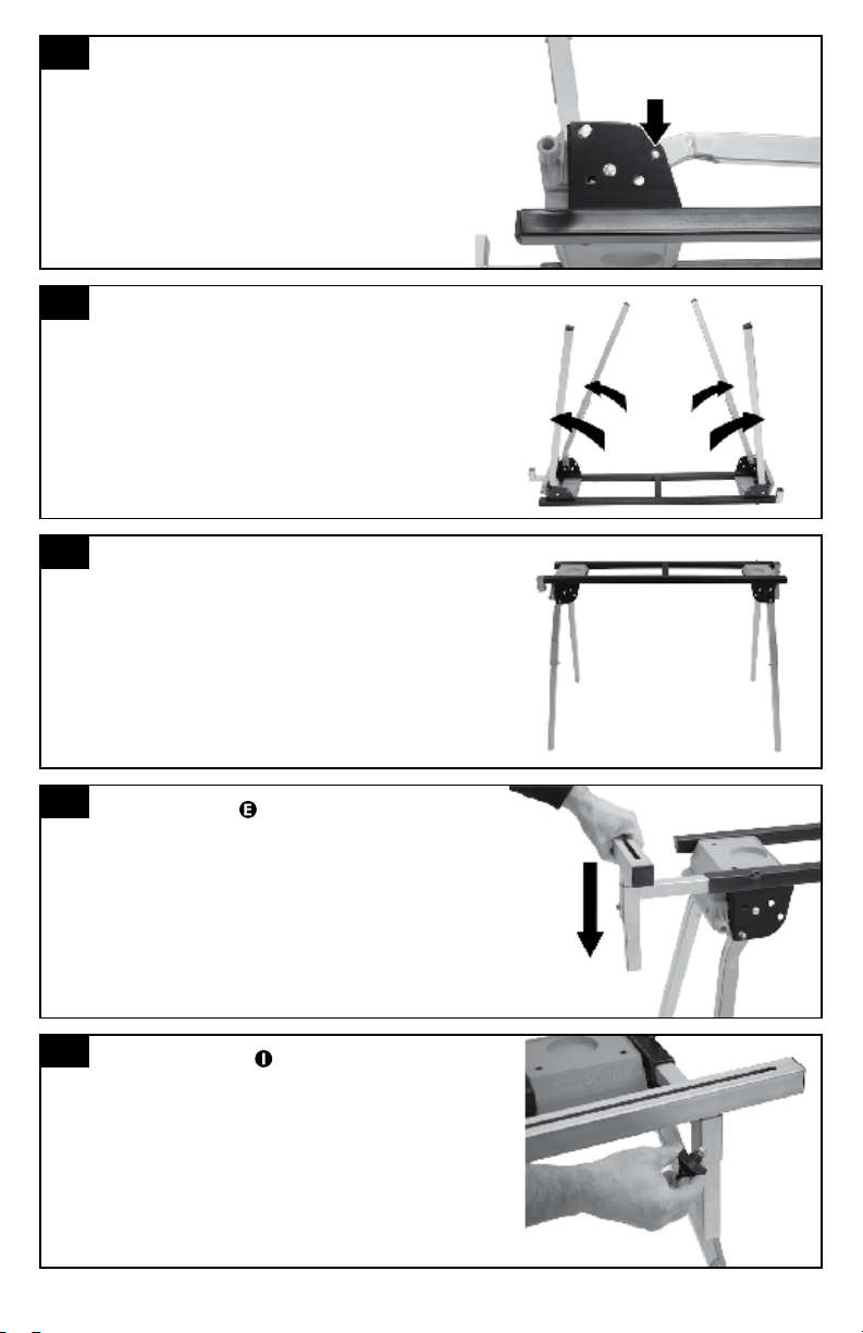
1
Press snap-pin to release from locked position.
2
Open all legs. Leg is fully opened when
snap-pin snaps into position.
3
Stand table upright.
4
Place “T” support into outrigger support.
Repeat on other side.
5
Screw 3-point knob into outrigger support
Repeat on other side.
PUSH
WARNING: Do not plug the 240V input cable from the
mitre saw stand into the 240V mains socket until the
mitre saw stand has been fully assembled.
Ensure the cable has NOT been trapped between any
of the assembly parts including the hinged legs.
Refer section "Using the 240V volt outlets" in this
manual prior to connecting and using the outlets.
4
Page 5
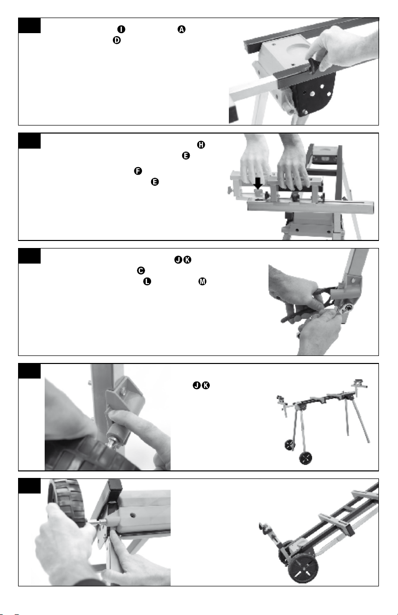
6
Screw 3-point knob into top frame to hold
outrigger supports
into place.
Never open outriggers wider than where the 3-point
knob can securely hold them in place.
Repeat on other side.
7
Line up the Roller Support Adjustment Knob to
the hole in the end of the “T” Assembly
.
Drop the Roller-Supports
into the hole and
slide across the “T” Assembly
.
Repeat on other side.
8
Attach the Right & Left Axel Brackets to the outside
bottom of the curved legs
(there are holes provided)
using the M6 x 45mm bolts
and M6 nuts .
Notice: the shaft on the axel brackets should be parallel
with the fl oor.
9
Press lever on lower wheel
axle
to insert and
release wheels.
Use lower position for...
OPEN MOBILITY
10
Press lever on upper axle
position to insert and
release wheels.
Use upper position for...
FOLDED MOBILITY
5
Page 6
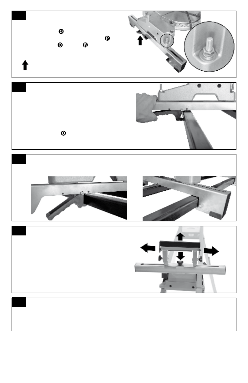
11
Attaching Machine Mounts*:
From the bottom, pass the M8 x 63mm
carriage bolt
through the slot in the machine
mount and secure with fl at washer
,
lock washer
, and nut . Repeat with all
mounting holes. Hand tighten only.
Note: For easier installation and removal, place
spring mounted handles in rear of machine.
12
Carefully lift the saw and place onto the
stand. Lock your machine mounts as shown
in Step 13.
Slide your saw forward or backward along
the machine mounts to best balance the
saw stand. Secure the saw by tightening the
carriage bolts
.
13
Note: Machine is locked into position when both the front and
the back of the machine mounts are secure as shown.
14
*
Adjust roller supports so rollers are on
the same plane as the work surface of
your machine.
For machines with offset mounting hole patterns (such as 3-hole or inset holes),
some models come with a hardware kit adapter. See the following page for
installation instructions and how to order.
6
Page 7

7
Page 8

WWW.DUROPRO.COM
WWW.PORTAMATE.COM
 Loading...