

DUROMAX XP2000iS Operator's Manual
- --- -
Dura
:Max
NEXT GENERATION POWER SYSTE MS
Inverter Gasoline
OPERATOR'S MANUAL
support@maxtool.com
Model:XP2000i5
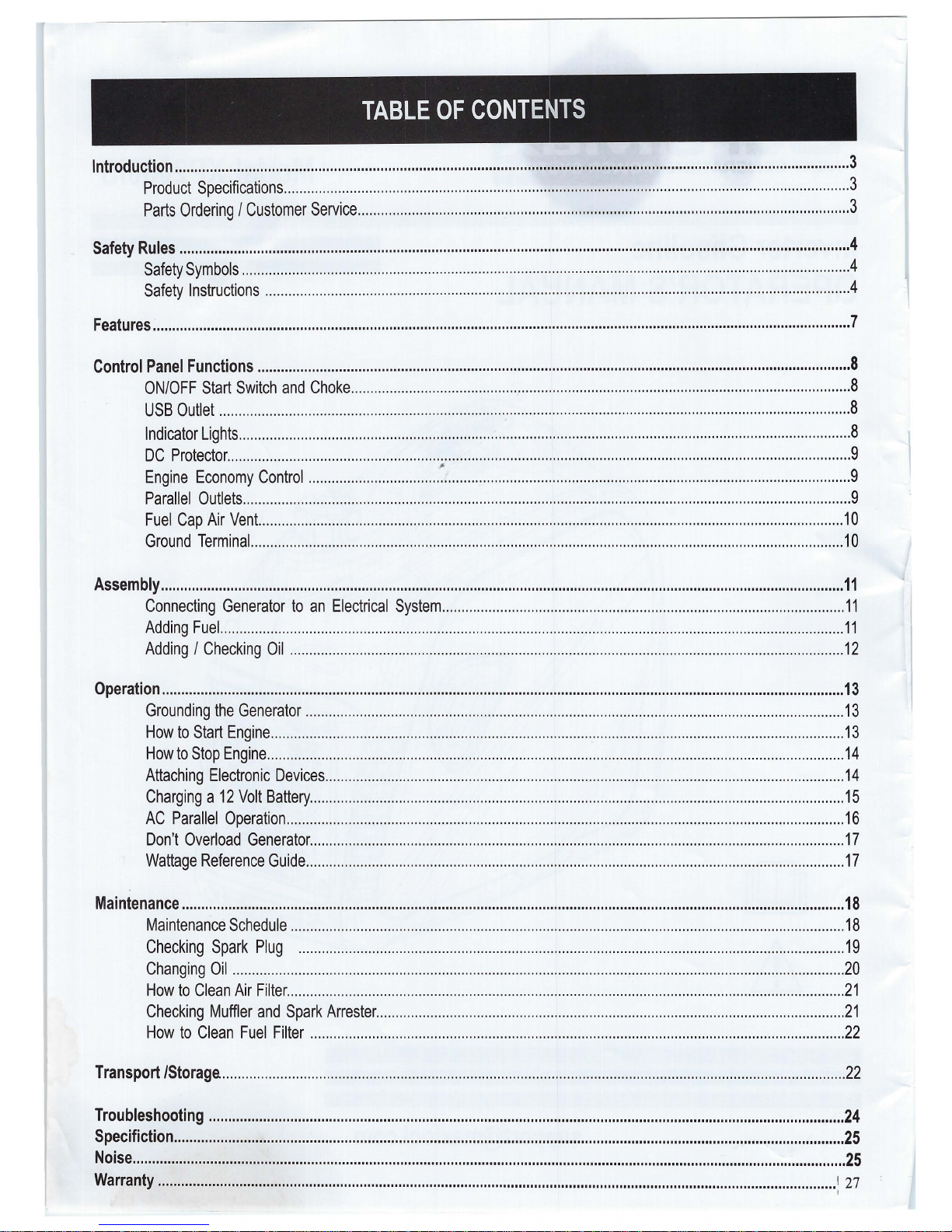
TABLE OF CONTENTS
Introduction .............................................................................................................................................................................. 3
Product Specifications .................................................................................................................................................. 3
Parts Ordering / Customer Service ............................................................................................................................... 3
Safety Rules ............................................................................................................................................................................. 4
Safety Symbols ........................................................................................................................................................ · · · · .4
Safety Instructions ....................................................................................................................................................... 4
Features .................................................................................................................................................................................... 7
Control Panel Functions ......................................................................................................................................................... 8
ON/OFF Start Switch and Choke ................................................................................................................................. 8
USB Outlet ................................................................................................................................................................... 8
Indicator Lights .............................................................................................................................................................. 8
DC Protector ................................................................................................................................................................. 9
Engine Economy Control ..................................
~
......................................................................................................... 9
Parallel Outlets ............................................................................................................................................................. 9
Fuel Cap Air Vent. ...................................................................................................................................................... 10
Ground Terminal. ........................................................................................................................................................ 10
Assembly ................................................................................................................................................................................. 11
Connecting Generator to an Electrical System ........................................................................................................ 11
Adding Fuel. ................................................................................................................................................................ 11
Adding / Checking Oil ............................................................................................................................................... 12
Operation ................................................................................................................................................................................ 13
Grounding the Generator ........................................................................................................................................... 13
How to Start Engine .................................................................................................................................................... 13
How to Stop Engine ..................................................................................................................................................... 14
Attaching Electronic Devices ...................................................................................................................................... 14
Charging a 12 Volt Battery .......................................................................................................................................... 15
AC Parallel Operation ................................................................................................................................................ 16
Don't Overload Generator .......................................................................................................................................... 17
Wattage Reference Guide ........................................................................................................................................... 17
Maintenance ........................................................................................................................................................................... 18
Maintenance Schedule ............................................................................................................................................... 18
Checking Spark Plug ............................................................................................................................................. 19
Changing Oil .............................................................................................................................................................. 20
How to Clean Air Filter ................................................................................................................................................ 21
Checking Muffler and Spark Arrester ......................................................................................................................... 21
How to Clean Fuel Filter .......................................................................................................................................... 22
Transport /Storage. ................................................................................................................................................................. 22
Troubleshooting .................................................................................................................................................................... 24
Specifiction ............................................................................................................................................................................. 25
Noise ........................................................................................................................................................................................ 25
Warranty ............................................................................................................................................................................... 1 27
I
INTRODUCTrON
Thank you for purchasing this superior quality portable generator from DUROMAX . When operating and maintaining this
product as instructed in this manual, your generator will give you many years of reliable service.
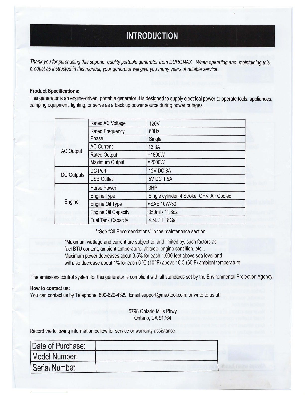
Product Specifications:
This generator is an engine~driven, portable generator.It is designed to supply electrical power to operate tools, appliances,
camping equipment, lighting, or serve as a back up power source during power outages.
Rated AC Voltage
120V
Rated Frequency
60Hz
Phase
Single
AC Current
13.3A
AC Output
Rated Output
*1600W
Maximum Output
*2000W
DC Port
12V DC 8A
DC Outputs
USB Outlet
5V DC 1.5A
Horse Power 3HP
Engine Type
Single cylinder, 4 Stroke, OHV, Air Cooled
Engine
Engine Oil Type *SAE 10W-30
Engine Oil Capacity
350ml 111.8oz
Fuel Tank Capacity
4.5L/ 1.18Gal
**See "Oil Recomendations" in the maintenance section.
*Maximum wattage and current are subject to, and limited by, such factors as
fuel BTU content, ambient temperature, altitude, engine condition, etc ...
Maximum power decreases about 3.5% for each 1,000 feet above sea level and
will also decrease about 1 % for each 6 °C ( 10 °F) above 16 C (60 F) ambient temperature
The emissions control system for this generator is compliant with all standards set by the Environmental Protection Agency.
How to contact us:
You can contact us by Telephone: 800-629-4329, Email:support@maxtool.com, or write to us at:
5798 Ontario Mills Pkwy
Ontario, CA 91764
Record the following information bellow for service or warranty assistance.
Date of Purchase:
Model Number:
Seria\ Number
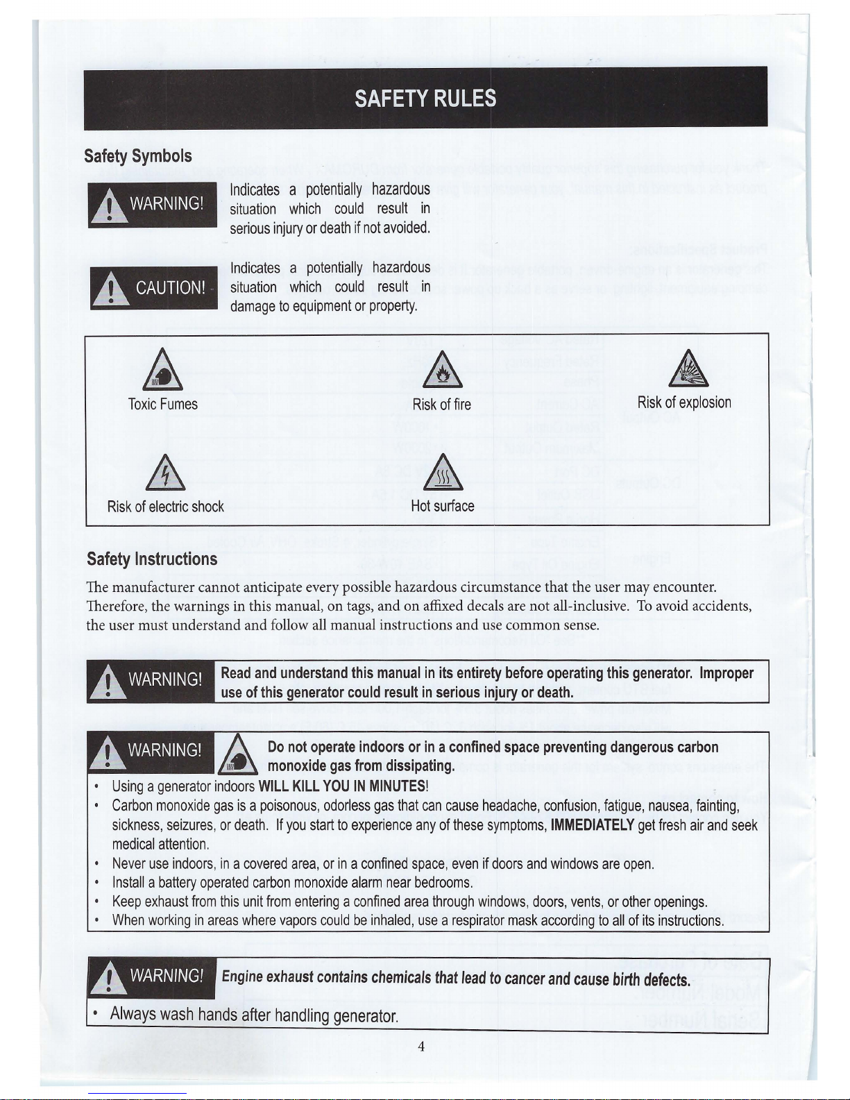
Safety Symbols
.A WARNING!
.A CAUTION!
Toxic Fumes
SAFETY RULES
Indicates a potentially hazardous
situation which could result in
serious injury or death if not avoided.
Indicates a potentially hazardous
situation which could result in
damage to equipment or property.
Risk of fire
&
Risk of explosion
Risk of electric shock
Hot surface
Safety Instructions
The manufacturer cannot anticipate every possible hazardous circumstance that the user may encounter.
Therefore, the warnings in this manual, on tags, and on affixed decals are not all-inclusive. To avoid accidents,
the user must understand and follow all manual instructions and use common sense .
.A WARNING!
.A WARNING!
Read and understand this manual in its entirety before operating this generator. Improper
use of this generator could result in serious injury or death.
A Do not operate indoors or in a confined space preventing dangerous carbon
~
monoxide gas from dissipating.
• Using a generator indoors WILL KILL YOU IN MINUTES!
• Carbon monoxide gas is a poisonous, odorless gas that can cause headache, confusion, fatigue, nausea, fainting,
sickness, seizures, or death. If you start to experience any of these symptoms, IMMEDIATELY get fresh air and seek
medical attention.
• Never use indoors, in a covered area, or in a confined space, even if doors and windows are open.
• Install a battery operated carbon monoxide alarm near bedrooms.
• Keep exhaust from this unit from entering a confined area through windows, doors, vents, or other openings.
• When working in areas where vapors could be inhaled, use a respirator mask according to all of its instructions.
_A. WARNING!
Engine exhaust contains chemicals that lead to cancer and cause birth defects.
• Always wash hands after handling generator.
4
_A WARNING!
SAFETY RULES
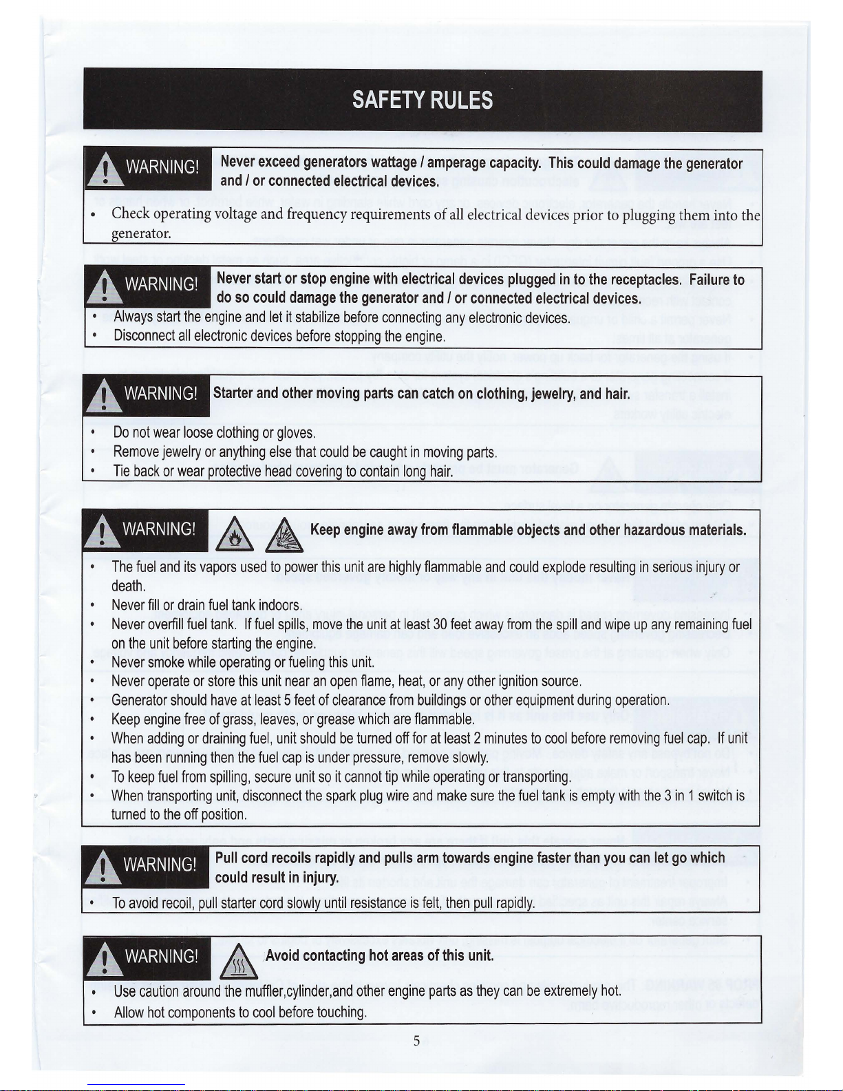
Never exceed generators wattage / amperage capacity. This could damage the generator
and / or connected electrical devices.
• Check operating voltage and frequency requirements of all electrical devices prior to plugging them into the
generator .
A WARNING!
Never start or stop engine with electrical devices plugged in to the receptacles. Failure to
do so could damage the generator and / or connected electrical devices.
• Always start the engine and let it stabilize before connecting any electronic devices.
• Disconnect all electronic devices before stopping the engine.
A WARNING!
Starter and other moving parts can catch on clothing, jewelry, and hair.
Do not wear loose clothing or gloves.
Remove jewelry or anything else that could be caught in moving parts.
Tie back or wear protective head covering to contain long hair.
A WARNING!
&, A, Keep engine away from flammable objects and other hazardous materials.
• The fuel and its vapors used to power this unit are highly flammable and could explode resulting in serious injury or
death.
• Never fill or drain fuel tank indoors.
• Never overfill fuel tank. If fuel spills, move the unit at least 30 feet away from the spill and wipe up any remaining fuel
on the unit before starting the engine.
• Never smoke while operating or fueling this unit.
• Never operate or store this unit near an open flame, heat, or any other ignition source.
• Generator should have at least 5 feet of clearance from buildings or other equipment during operation.
• Keep engine free of grass, leaves, or grease which are flammable.
• When adding or draining fuel, unit should be turned off for at least 2 minutes to cool before removing fuel cap. If unit
has been running then the fuel cap is under pressure, remove slowly.
• To keep fuel from spilling, secure unit so it cannot tip while operating or transporting.
• When transporting unit, disconnect the spark plug wire and make sure the fuel tank is empty with the 3 in 1 switch is
turned to the off position.
A WARNING!
Pull cord recoils rapidly and pulls arm towards engine faster than you can let go which
could result in injury.
To avoid recoil, pull starter cord slowly until resistance is felt, then pull rapidly.
--- - ~~
A WARNING!
~
,Avoid contacting hot areas of this unit.
Use caution around the muffler,cylinder,and other engine parts as they can be extremely hot.
• Allow hot components to cool before touching.
5
_A. WARNING!
SAFETY RULES
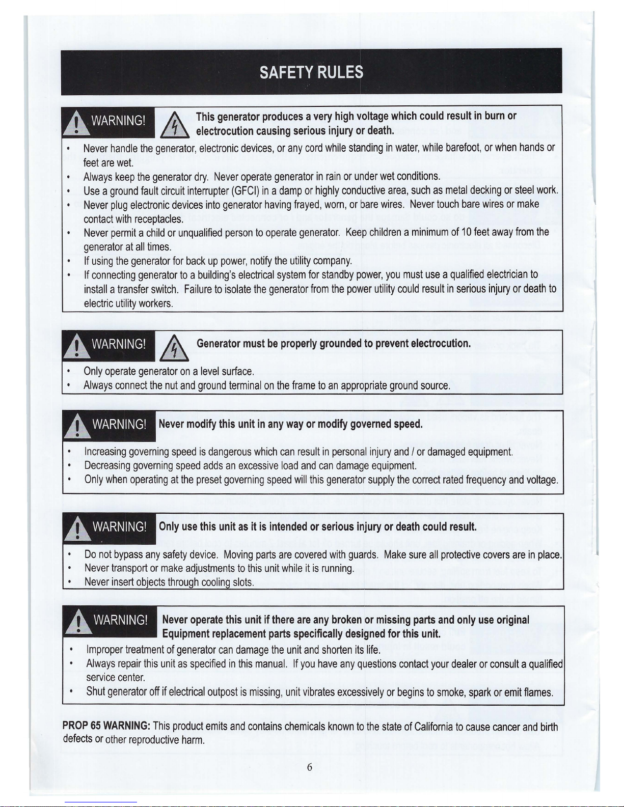
A_ This generator produces a very high voltage which could result in burn or
~
electrocution causing serious injury or death.
Never handle the generator, electronic devices, or any cord while standing in water, while barefoot, or when hands or
feet are wet.
• Always keep the generator dry. Never operate generator in rain or under wet conditions.
Use a ground fault circuit interrupter (GFCI) in a damp or highly conductive area, such as metal decking or steel work.
Never plug electronic devices into generator having frayed, worn, or bare wires. Never touch bare wires or make
contact with receptacles.
Never permit a child or unqualified person to operate generator. Keep children a minimum of 10 feet away from the
generator at all times.
If using the generator for back up power, notify the utility company.
If connecting generator to a building's electrical system for standby power, you must use a qualified electrician to
install a transfer switch. Failure to isolate the generator from the power utility could result in serious injury or death to
electric utility workers.
A_ wARNING!
& Generator must be properly grounded to prevent electrocution.
Only operate generator on a level surface.
Always connect the nut and ground terminal on the frame to an appropriate ground source.
A. WARNING!
Never modify this unit in any way or modify governed speed.
Increasing governing speed is dangerous which can result in personal injury and / or damaged equipment.
Decreasing governing speed adds an excessive load and can damage equipment.
Only when operating at the preset governing speed will this generator supply the correct rated frequency and voltage.
A. WARNING!
Only use this unit as it is intended or serious injury or death could result.
Do not bypass any safety device. Moving parts are covered with guards. Make sure all protective covers are in place.
Never transport or make adjustments to this unit while it is running.
Never insert objects through cooling slots.
A. WARNING!
Never operate this unit if there are any broken or missing parts and only use original
Equipment replacement parts specifically designed for this unit.
Improper treatment of generator can damage the unit and shorten its life.
Always repair this unit as specified in this manual. If you have any questions contact your dealer or consult a qualified
service center.
Shut generator off if electrical outpost is missing, unit vibrates excessively or begins to smoke, spark or emit flames.
PROP 65 WARNING: This product emits and contains chemicals known to the state of California to cause cancer and birth
defects or other reproductive harm.
6
A
B
C
D
J
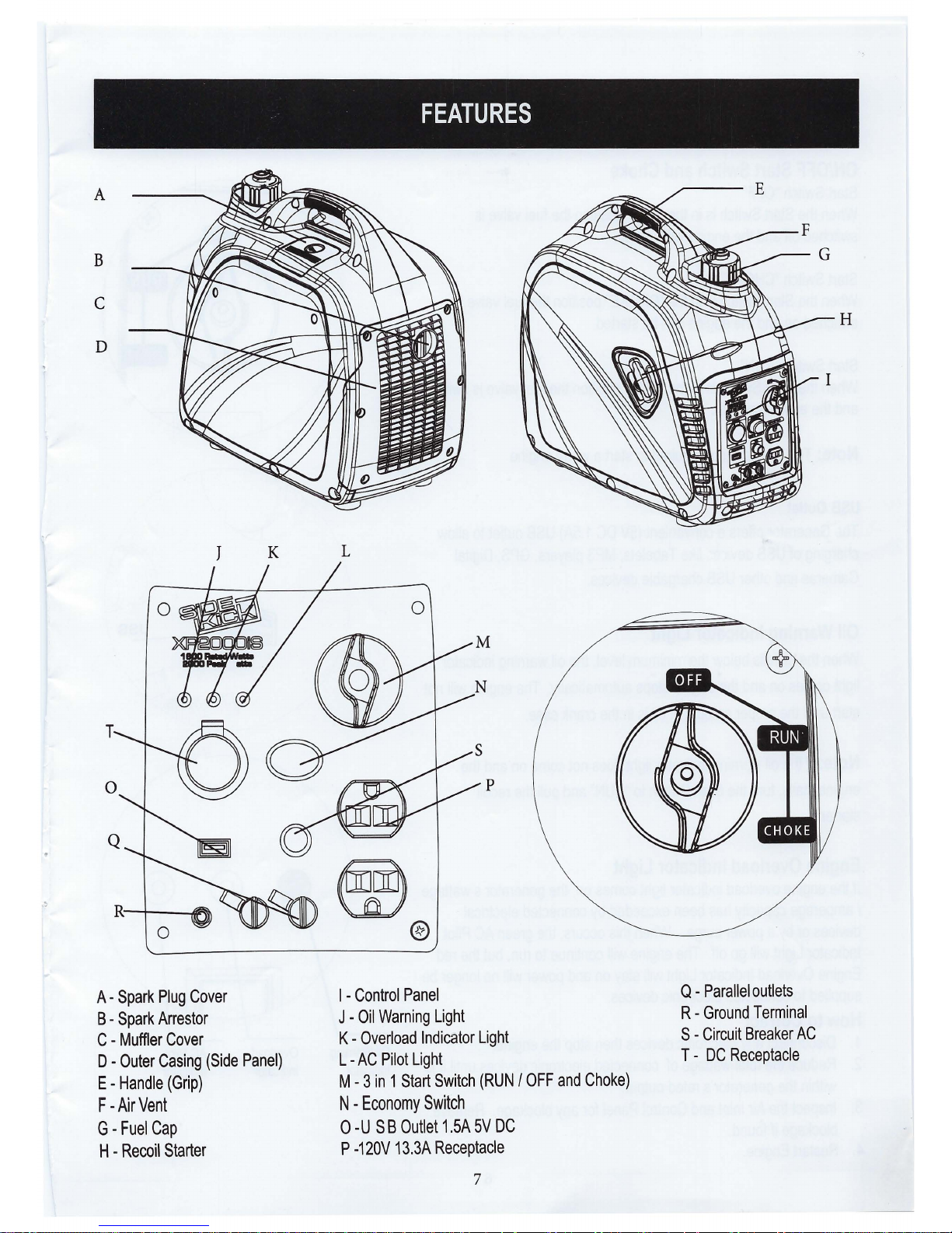
A - Spark Plug Cover
B - Spark Arrestor
C - Muffler Cover
K
D - Outer Casing (Side Panel)
E -Handle (Grip)
F -Air Vent
G-Fuel Cap
H - Recoil Starter
FEATURES
L
0
I - Control Panel
J -Oil Warning Light
K -Overload Indicator Light
L -AC Pilot Light
M -3 in 1 Start Switch (RUN/ OFF and Choke)
N -Economy Switch
0 -U SB Outlet 1.5A 5V DC
P -120V 13.3A Receptacle
7
Q - Parallel outlets
R - Ground Terminal
S - Circuit Breaker AC
T - DC Receptacle
H
CONTROL PANEL FUNCTIONS
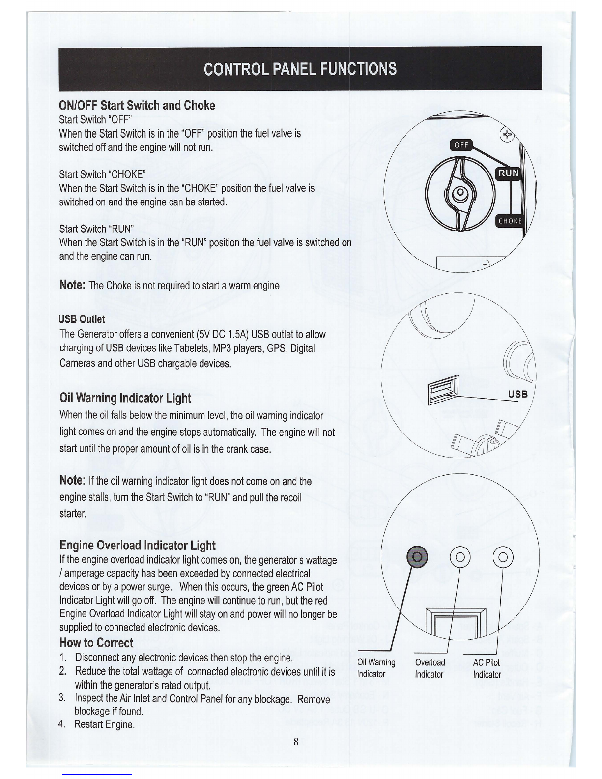
ON/OFF Start Switch and Choke
Start Switch "OFF"
When the Start Switch is in the "OFF" position the fuel valve is
switched off and the engine will not run.
Start Switch "CHOKE"
When the Start Switch is in the "CHOKE" position the fuel valve is
switched on and the engine can be started.
Start Switch "RUN"
When the Start Switch is in the "RUN" position the fuel valve is switched on
and the engine can run.
Note: The Choke is not required to start a warm engine
USB Outlet
The Generator offers a convenient (5V DC 1.5A) USB outlet to allow
charging of USB devices like Tabelets, MP3 players, GPS, Digital
Cameras and other USB chargable devices.
Oil Warning Indicator Light
~---~USB
When the oil falls below the minimum level, the oil warning indicator
light comes on and the engine stops automatically. The engine will not
start until the proper amount of oil is in the crank case.
Note: If the oil warning indicator light does not come on and the
engine stalls, turn the Start Switch to "RUN" and pull the recoil
starter.
Engine Overload Indicator Light
If the engine overload indicator light comes on, the generators wattage
I amperage capacity has been exceeded by connected electrical
devices or by a power surge. When this occurs, the green AC Pilot
Indicator Light will go off. The engine will continue to run, but the red
Engine Overload Indicator Light will stay on and power will no longer be
supplied to connected electronic devices.
How to Correct
1. Disconnect any electronic devices then stop the engine. Oil warning overload
2. Reduce the total wattage of connected electronic devices until it is Indicator Indicator
within the generator's rated output.
3. Inspect the Air Inlet and Control Panel for any blockage. Remove
blockage if found.
4. Restart Engine.
8
AC Pilot
Indicator
..
CONTROL PANEL FUNCTIONS
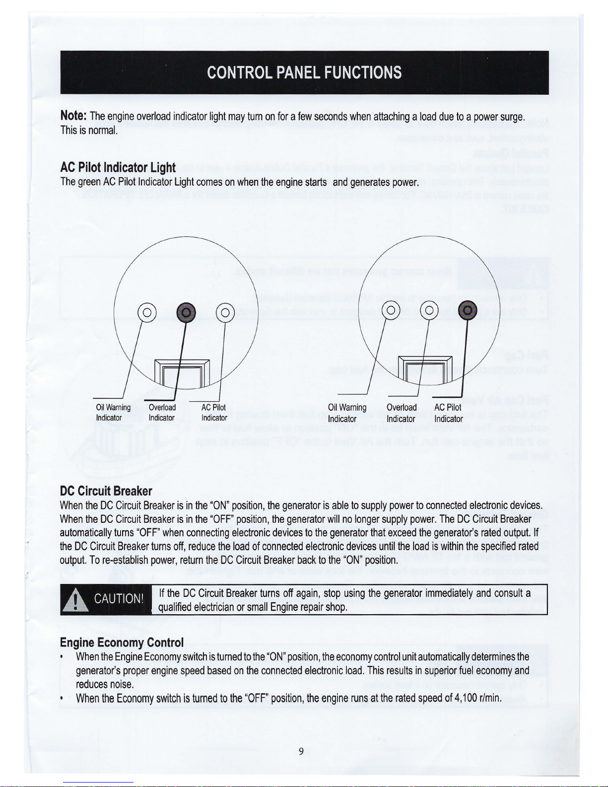
Note: The engine overload indicator light may turn on for a few seconds when attaching a load due to a power surge.
This is normal.
AC Pilot Indicator Light
The green AC Pilot Indicator Light comes on when the engine starts and generates power.
Oil Warning Overload
Indicator Indicator
DC Circuit Breaker
AC Pilot
Indicator
Oil Warning
Indicator
Overload AC Pilot
Indicator Indicator
When the DC Circuit Breaker is in the "ON" position, the generator is able to supply power to connected electronic devices.
When the DC Circuit Breaker is in the "OFF" position, the generator will no longer supply power. The DC Circuit Breaker
automatically turns "OFF" when connecting electronic devices to the generator that exceed the generator's rated output. If
the DC Circuit Breaker turns off, reduce the load of connected electronic devices until the load is within the specified rated
output. To re-establish power, return the DC Circuit Breaker back to the "ON" position.
A CAUTION!
If the DC Circuit Breaker turns off again, stop using the generator immediately and consult a
qualified electrician or small Engine repair shop.
Engine Economy Control
• When the Engine Economy switch is turned to the "ON" position, the economy control unit automatically determines the
generator's proper engine speed based on the connected electronic load. This results in superior fuel economy and
reduces noise.
• When the Economy switch is turned to the "OFF" position, the engine runs at the rated speed of 4,100 r/min.
9
 Loading...