

Page 1
MODEL: XP15000EH
This manual provides information regarding the operation and maintenance of these products.
We have made every effort to ensure the accuracy of the information in this manual.
We reserve the right to change this product at any time without prior notice.
Page 2

INTRODUCTION
Congratulations on your selection of a this generator. We are certain you will be pleased with your purchase of one of
the finest generators on the market.
We want to help you get the best results from your new generator and to operate it safely. This manual contains all the
information on how to do that; please read it carefully.
As you read this manual, you will find information preceded by a symbol.
That information is intended to help you avoiddamage to your generator, other property, or
the environment.
W
e suggest you read the warranty policy to fully un derstand its coverage and your responsibilities of ownership.
AFEWWORDSABOUTSAFETY
Your safety and the safety of others are very important. And using this generator sa fely is an important responsibility.
To help you make informed decisions about safety, we have provided operating procedures and other information on
labels and in this manual. This information alerts you to potential hazards that could hurt you or others.
Of course, it is not practical or possible to warn you about all the hazards associated with operating or maintaining a
generator. You must use your own good judgement.
You will find imp ortant safety i nformation in a variety of forms, including:
Safety Labels on the generator
.
Safety Headings such as IMP ORTANT SAFETY INFOR MATION.
Safety Section such as GENERATOR SAFETY.
Instructions howtousethisgeneratorcorrectlyandsafely.
This entire book is filled with important safety information please read it carefully.
When your generator need s scheduled main t enance, keep in mind your servicing dealer is specially trained in
servicing generators. Your authorized servicing deale r is dedicated to your satisfaction and will
be pleased to answer yo ur questions and concerns.
Safety Messages preceded by a safety alert symbol and one of three signal words, DANGER, WARNING, or
CAUTION.
1
Page 3

CONTENTS
GENERATOR SAFETY
IMPORTANT SAFETY INFORMATION ……………………………………………………………………………………………………………………….….4
Operator Respons ibility …………………………………………………………………………………………………………………………………….…..4
Carbon Monoxide Hazards ……………………………………………………………………………………………………………………… ……….….. 4
Electric Shock Hazards ………………………………………………………………………………………………………………………………… …….…. 4
Fire and Burn Hazards ………………………………… ………… ………………………… …………… ……………………………………… ………… .…..4
Refuel With Care ……… …………………………………… …………… ………………………… ……………………………… ………………… ……… .…..4
SAFETY LABEL LOCATIONS ………………………………………………………………… …………………………………… …………… …………. …………5
CONTROLS & FEATURES
COMPONENT & CONTROL L OCATIONS ………………………… …………………………………………………………………………………… .………6
CONTROLS ……………………………………………………………………… ………………… …………… ……………………… …………… …………… ……… 8
Fuel Valve Lever ……………………………………………………………………… ………………………… …………… ………………… …………….…… 8
Choke Knob ………………………………………………………………… ………… …………… ………………………… ……………………………….…… 8
Engine Switch ………………………………………………………… ……………… ………………………… ………………………… …………… …….…… 8
Circuit Breaker …………………………………………………………………………………………………… …………………… …………… ………….…… 8
FEATURES …………………………… ………………… …………………… …………………………… …………… ………………………… …………… …….…… 9
Oil Alert System …………………………………………………………………………………………… ………………… …………… ………………… .…… 9
Ground Terminal ……………………………………… ………………… …………… ………………………… ……………………………… …………….… 9
Fuel Gauge ……………………………………………………… …………… ………… ………………………… …………… ………………… ………………… 9
Volt Meter …………………………………………………… ………………………… ……………… ………………………… ………… ………………… …… 9
Hour Meter ………………………………………………………………………………………… ………………… …………… ………………… …….………10
AC Output Terminal/Cover ……………………….……………………………………………… …………… ………… ………………………….………10
………………………………………………………………………………………………… …………… ………………… ……………… . 4
………………………………………………………………………………………………………………………………….………… 6
BEFORE OPERATION
ARE YOU READY TO GET STARTED? ………………………………………………… ……………… …………………… ………… …………….……… .. 11
Knowledge …………… ……………………………………… …………… ………………………… ……………………………… ……….………..………… 11
IS YOUR GENERATOR READY TO GO? …………… …………………………………… …………… …………… …………………….………..…………
Check the Engine ……… ………………………… …………………………… …………………… …………… ………………… ……….………..…………11
Check the Battery ………………………………………………………………………………………… …………… …………… ……….………..……… 11
OPERATION
SAFE OPERATING PRECAUTION ………………………… …………………………………… …………… ………………………………… .………..…….12
STARTING THE ENGINE ……………… …………… ………………… …………… ………………………… …………… …………… ……….………..………12
STOPPING THE ENGINE …………………………………………………………………………………………………………… ………… .………..…………13
AC OPERATION ……………………………………………………………………………………………………… ……………………………….……… ..…… ..14
AC Receptacle ……………… ………………… ……………………… …………………………… ………………… ………………… ……….……… ..…… ..14
AC OUT PUT TERMINAL ……………………………………………………………………………………………………… …………… ….………..……… ..15
AC Applications ……………………………………… …………………………… …………………… ……………………………… ……….………..………16
STANDYBY POWER ………………………………………………………………… ……………… ……………………… …………… ……….………..………. 17
Connection to a Building’s Electrical System …………………………………………………… …………… …………………… .………..……. 17
System Ground ……………………………………… ………………… …………………………… …………… …………… …………………… .………..… 17
Special Requirements …………………………………………… ……………… ……………………… ………………… ………………….………..…….17
………………………………………………………………………………………………………………… ………………… ……… .………..…….. 12
SERVICING YOUR GENERATOR
THE IMPORTANCE OF MAINTENANCE ………………………………………………………… ………………………………… .………..…………... 18
MAINTENANCE SAFETY ……………………………………………………………………………… …………………………………… ……….……… ..……18
……………………………………………………………………………………………………………… ………………… …….……… ..…11
………………………………………………………………………………………… ……………… .………..…….….. 18
11
2
Page 4

CONTENTS
Safety Precautions …………………………………………………………………………………………… …………….………..……………………… .…18
MAINTENANCE SCHEDULE …………………………………………………………………………… …………… …………… .………..…………………… 19
REFUELING …………………………………………………………………………… ………………………… …………… …….……… ..………………………… 19
FUEL RECOMMENDATIONS ………………………………………………………………………………………… ………………… ……… .………..…….. 20
Gasolines Containing Alcohol ……………………………………………………………… ……………………………………….………..…………… 21
ENGINE OIL LEVEL CHECK ………………………… …………………… ……………………………………… …………… ……… .………..………………..21
ENGINE OIL CHANGE ……………… …………… …………………………………… …………………… ………………… …………… …………….……… ...22
OIL FILTER CHANGE …………………………………………………… …………… ……… ………………………… …… …………………… .………..……….
ENGINE OIL RECOMMENDATION ………………………………………………………………………………………………………….………..………. 23
AIR CLEANER SERVICE ………………………………………………………… ………………………… …………… …………………… .……….…………...23
FOAM AIR FILTER CLEANING ……………… ………………… …………… ………………………………………… ………… ……………… .………..….. 24
SEDIMENT CAP CLEANING …..…………………………………………………… …………………………… …………… …………………… .………..…..24
SPARK PLUG SERVICE ………………………………………………………… ……………………………………… ………… ……………….………..……… 24
BATTERY SERVICE ………………………… ………………… ……… …… ………………………… …………… …… …… ……………….………..…………… 25
Battery Removal ………………………………………………………………………………………………………………… …….………..……………….25
Battery Charging …………………………………………………………………………………… ………………………… …… .………..………………….26
22
STORAGE
STORAGE RECAUTION …………………………………………………………………………………… …………………………………… .………..………..28
STORAGE PROCEDURE ……………… ………………………… …… …………………… ………………… ………………… …………………….………..….29
STORAGE PRECAUTIONS ……………………………………………………………… ……… ……… ………… …… ……………… …… ………….………...30
REMOVAL FROM STORAGE ………………………………………… …………… …………… ……………………… …………… ……………… .………..…30
TRANSPORTING
TAKING CARE O F UNE XP ECTED PROBL E M S ………………………………………………………………………………………………….……… ..…..32
ENGINE PROBLEMS ……………………………………………………………………………… ………………… ………………… ……….………..………….32
GENERATOR PROBLEMS ………………………………………………………………………………………………………………….………..……………..33
TECHNICAL INFORMATION
SERIAL NUMBER LOCATION …………………………………………………………… ………………………… …………… ……… .………..……………. 34
CARBURETOR MOD IFI CATION FOR HIGH ALTITUDE
OPERATION ……………………………………………………………………………………………………………………………………… .………..….……… 34
SPECIFICATIONS ……………………………………………………………………… ……………………………… …………… …………….……… ..………... 35
WIRING DIAGRAM ………………………………………………………………………………………… …………… ……………… .………..………………..36
……………………………………………………………………………………………………… …………… ………………… ………… .………..……….28
Cleaning …………………………………………………………………………………………………………………………… ……………….………..………28
Fuel ……………………………………………………………………………………… ………………… …………………… ………… ………….………..……..28
……………………………… …………………………………………… ……………… ……………… ……………… ………….………..…....31
Engine Will Not Start …………………………………………………… ………………………… ……………………………… …….………..……………32
Engine Lacks Power ……………………………………………………………………………………………………… ………………… .………..……….. 32
No Power at the AC Receptacles …………………………………………………………… ……………………………… .……… ..………………….
………………………………………………………………………………………………… ……………… .………..………. 34
33
OPTIONAL PARTS
Wheel Kit ………………………………………………………… …………………… ………… …………………………… .………..……………………….… 38
INDEX
………………………………………………………………………………………………………… ………………… ………………… .………..…….………
…………………………………………………………….………………………………………………………………… …….………..…….38
3
39
Page 5

GENERATOR SAFETY
IMPORTANT SAFETY INFORMATION
THIS generators are designed for use with electrical equipment that has suitable power requirements. Other uses can
result in injury to the op erator or damage to the generator and other property.
Most acciden ts can be prevented if you follow all instructions in this manual and on the generator. The most comm on
hazards are discussed below, along with the best way to protect yourself and others.
Operator Re sponsibility
Know how to stop the generator quickly in case of emergency.
Understand the use of all generator controls, output receptacles, and connections.
Be sure that anyone who operates the generator receives proper instruction. Do not let children operate the generator
without parental superv isi on.
Carbon Monoxide Hazards
Exhaust contains poisonous carbon monoxide, a colorless, odorless gas. Breathing carbon monoxide can cause loss
of consciousness and may lead to death.
If you run the generator in an a rea that is confined , or even pa rtly enclosed area, the air you breathe could contain
dangerous amount of exhaust gas.
Never run your generator inside a garage, house, or near open windows or doors.
Electric Shock Hazards
The generator produces enough electric power to cause a serious shock or electrocution if misused.
Using a generator or electrical appliance in wet conditions, such as rain or snow, or near a pool or sprinkler system,
or when your hands are wet, could result in electrocution. Keep the generator dry.
If the generator is stored outd oors, unprotected from the weather, check all of the electrica l components on the
control pan el before each use. Moisture
or ice can cause a malfunction or short circuit in electrical
components that could result in electrocution.
Do not connect to a building’s electrical system unless an isolation switch has been installed by a qualified electrician.
Do not use th e generator without pro tective switch-off device.
Fire and Burn Hazards
The exh aust system gets hot enough to ignite some materials.
Keep the generator at least 1 meter away from buildings and other equipment during o peration.
Do not enclose the generator in any structu re.
Keep f lammable materials away from the generator
The muffler becomes very hot during operation an d remains hot for a while after stopping the engine. Be careful
not to touch the muffler while it is h ot. Let the engine cool before storing the generator indoors.
Refuel With Care
Gasoline is extremely f lammable, an d gasoline vapor can expl o de. Allow the engin e to cool if the generator has been in
operation. Refuel only outdoors in a well ventilated area with the engine OFF. Do not overfill the fuel tank. Never smoke
near gasoline, and keep other flames and sparks away. Always store gasoline in an approved container. Make sure that
a
ny spilled fuel has been wiped up before starting the engine.
4
Page 6
GENERATOR SAFETY
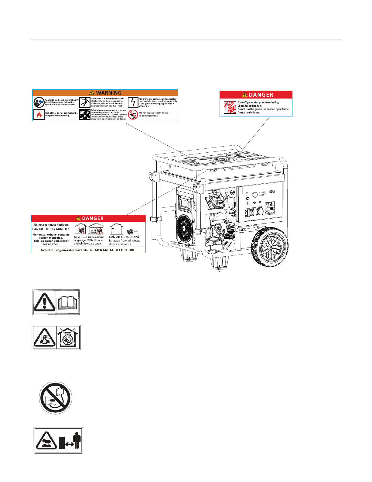
SAFETY LAB EL LOCATIONS
These labels warn you of potential hazards that can cause seriou s injury. Read them carefully. If a label comes off
or becomes hard to read, contact your THIS servicing dealer for a placement.
THIS generator is designed to give safe and dependable service if operated according to
instructions.
Read and understand the Owner ’s Manual before operating the generator. Failure to do so could
result in personal injury or equipment damage.
Exhaust contains poisonous carbon monoxide, a colorless, odorless gas. Breathing carbon
monoxide can cause loss of consciousness and may lead to death.
If you run the generator in an area that is confined, or even partially enclosed area, the air you
breathe could contain a dangerou s amount of exhaust gas.
Never run your generator inside a garage, house or near open windows or doors.
Do not connect to a building’s electrical system unless an isolation switch has bee n installed by
a qualified electrician.
Connections for standby power to a building ’s Electrical system must be made by a
qualified Elec trician and must comply with all app licable laws and electrical codes. Im proper
connections can allow electrical current from the generator to bac k feed into the utility lines.
Such back feed may electrocute utility company workers or others who contact the lines during
a power outage, and w hen utility power is restored, the generator may explode, burn,
or cause fires in the building’s electrical system.
A hot exhaust system can cause serious burns. Avoid contact if the engine has been running.
5
Page 7
CONTROLS & FEATURES
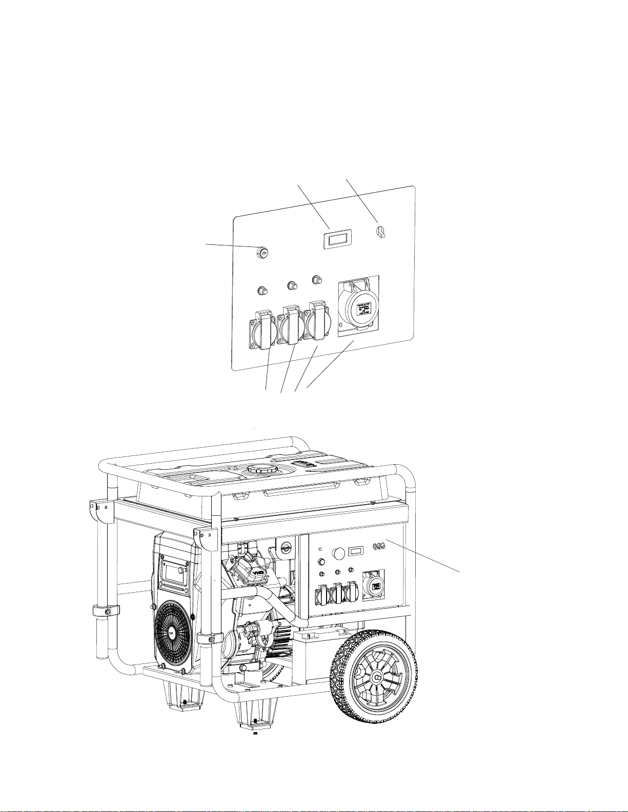
COMPONENT & CONTROL LOCATIONS
Use the illustrations on these pages to locate and identif y the most frequently used controls.
ENGI N E
SWITCH
HOU
R
METER
C RECEPTACLES
A
CIRCU I T
BREAKE R
CONTROL PANEL
6
Page 8
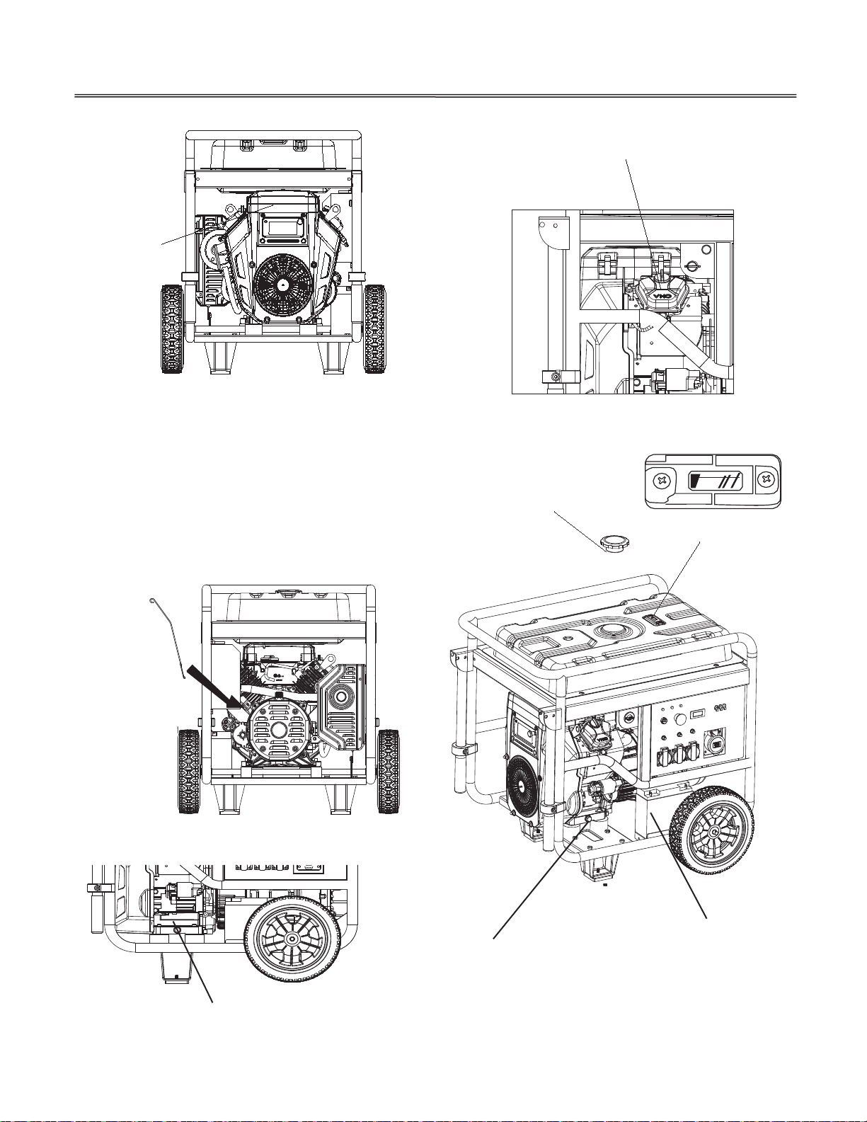
CONTROLS & FEATURES
AIR CLEANE R
CY LI ND E R
HEAD
OIL LEVEL
DIPSTIC K
FUEL TAN K CA P
EMPTY FULL
FUEL
GA UG E
ELECTR I C
STARTER
BATTERY
OIL DRAIN TUBE
7
Page 9
CONTROLS & FEATURES
CONTROLS
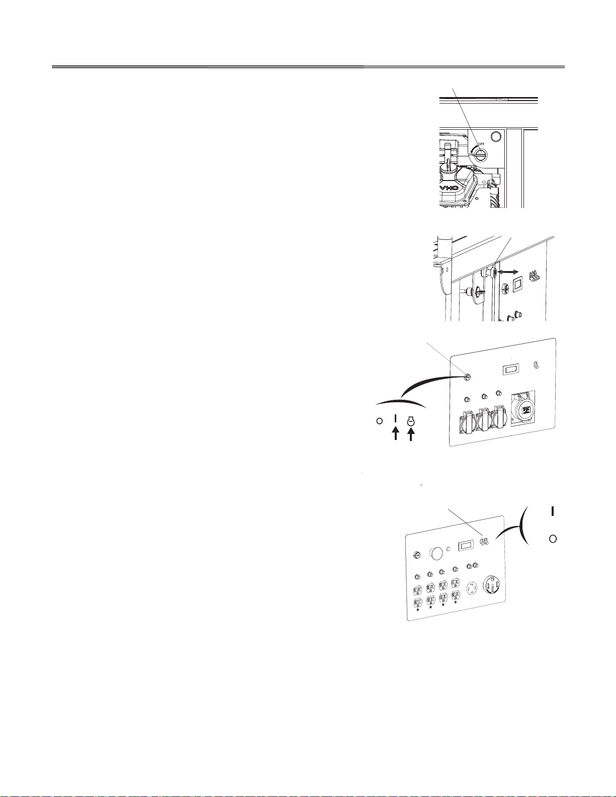
Fuel Valve Lever
The fue l valve lever is located between the fuel tank and carburetor.
The fu el valve lever must be in the ON position for the engine to run.
After stopping the engine, turn the fuel valve lever to the OFF position.
Choke Knob
The choke knob opens
and closes th e choke valve in the ca rburetor.
The CLOSED position enriches the fuel mixture for starting a cold
engine.
The OP EN position provides the correct fuel mixture for operation
after starting, and for restarting a warm engine.
Engine Switch
Engine Switch
The engine switch controls the ignition system, and it operates the
electric starter.
FUEL VALVE LE VE
R
CHO K E KN O B
OPEN
CLOSED
OFF -- Stops the engine. The engine switch key can be removed/
inserted.
ON -- Running position.
START -- Operates the electric starter.
Circuit Breaker
The circu it breaker will automatically switch
OFF, if there is a short circuit or a significant
overload at the receptacles or output
terminals.
The circuit breaker may be used to switch
thegeneratorpowerONorOFF.
OFF
ON
STAR
CIRCUIT
BREAKE R
ON
OFF
8
Page 10
CONTROLS & FEATURES
FEATURES
Oil Alert System
The Oil Alert system is designed to prevent engine damage caused by an insufficient amou nt of oil in the
crankcase. Before the oil level in the crankcase can fall below a safe limit, the O il Alert system will automatically stop the
engine
(the engine switch will remain in the ON position).
If the engine stops and will not restart, check the engine oil level (see Page 21) before trouble shooting in other areas.
Ground Terminal
The ground terminal is connected to the frame of the generator, the metal noncurrent carryin g parts of the ge nerator,
and the ground terminals of each receptacle.
Before using the ground terminal, consult a qualified electrician, electrical inspector, or loc al agency having jurisdiction
for local codes or ordinances that apply to the intended use of the generator.
Attention ! It is compulsorily to make protective earthing before
operating the
Rules for Installing Electrical Facilities.
generator. Protective earthing must correspond to
Earthing devices and grounding conductors must be selected in accordance
with chapters 1.7 and 1.8 of Rules for Installing Electr ical Facilities.
GROUND
TERM IN A L
Usually, copper g rounding conductor needed of minimum 4mm
Fuel Gauge
The fuel gauge is a mechanical device that measures the fuel level in the
tank. The red indic ator in the window will reflect the level in relation
to full or empty. To provide increased operating time, start with a full
tank before begi nning operation. Chec k the fuel level with the generator
on a level surface. Always refuel with the engine OFF and cool.
Hour Meter
The hour meter indicates the hours the generator has been operated.
Use it to determine when s cheduled maintenance should be
Performed
.
FUEL GAUGE
Hour Meter
EMPTY FULL
²
section.
FUEL TAN K C A P
9
Page 11
BEFORE OPERATION
ARE YOU READY TO GE T STARTED?
Your safety is your responsibility. A little time spent in preparation will significa ntly reduce your risk of injury.
Knowledge
Read and understand this manual. Know what the controls do and how to operate them.
Familiarize yourself with the generator and its operation before you begin usin g it. Know how to quic kly shut off
the generator in case of an emergency.
If the generator is being used to power appliances, be sure that they do not exceed the generator’s load rating .
IS YOUR GENERATOR READY TO GO?
For your s a fety, and to maximize the service life of your equ ipment, it is very important to take a few moments before
you operate the generator to check its cond ition. Be sure to take care of a ny problem you find, or have your servicing
To prevent a possible fire, keep the generator at least 1 meter a way from building walls and other equipment during
operation. Do not plac e flammable objects close to the engine.
Before beginning your preoperation checks, be sure the generator is on a level surface and the engine switch is in the
OFF position.
Check the Engine
Check the oil level (see page
19). A low oil level will cause the Oil Alert system to shut down the engine.
Check the air cleaner (see page 21).A dirty air clean er element will restrict air flow to the carburetor, reducing engine
and generator performance.
Check the fuel level (see pa ge 18).Starting with a full tank will help to eliminate or reduce operating interrup tions for
refueling.
Check the Battery
Check the fuel electrolyte level (see page 24).
If the electrolyte level is
below the LOWER level, sulfation and battery plate dama ge will occur.
BATTE RY
10
Page 12
OPERATION
SAFE OPERATING PRECAUTIONS
Before operating the generator for the first time, please review th e GENERATOR SAFETY section and the chapter titled
BEFORE OPER ATION.
For your safety, do not operate the generator in an enclosed area such as a garage. Your generator’s exhaust contains
poisonous carbon monoxide gas that can collect rapidly in an enclosed area and cause illness or death.
Before connecting an AC appliance or power cord to the generator:
Use grounded 3 prong extension cords
for single phase generator and 5 prong extension cords for three generator,
tools, an d appliances, or double insulated tools and appliances.
Inspect cords and plugs, and replace if dama ged.
Make sure that the appliance is in good working order. Faulty appliances or power cords can create a potential for
electric shock.
Make sure the elect rical rating of the tool or appliance does not exceed that of the gen erator. Never exceed the
maximum power rating of the generator. Power levels between rated and maximum may be used for no m ore than
30 minutes.
Operate the generator at least 1 meter away from buildin gs and other equ ipment.
Do not operate the generator in an enclosed structure.
ON
STARTING THE ENG INE
OFF
1. Make sure that the circu it breaker is in the OFF position.
The generator maybe hard to start if a load is connected.
CIRCU I T
BREA K E R
2. Turn the fuel valve lever to the ON position.
OFF
ON
FUEL VALVE LEV ER
11
Page 13

OPERATION
Pull the choke knob to the CLOSED position to start a cold engine.
3.
CLOSED
Leave the choke knob in the OPEN position to restart a warm engine.
Start the engine. Turn the engine switch to the START position, and hold
4.
it there until the engine starts. When the engine starts, release the
key,allowingtheswitchtoreturntotheONposition.
If
theenginefailstostartwithin5seconds,releasethekey,andwaitat
ON
least 10 seconds before operating the starter again.
OFF
STAR
NOTICE
Using the electric starter for more than 5 seconds at a time will Overheat the starter motor and can damage it.
5.
If the choke knob was pulled to the CLOSED position to start th e engine,
gradually move it to the OPEN position as the engine warms up.
CHOK E KNO B
3-1.
4-1.
ENGIN E SWI T CH
6
. Generator needs to operate for 3-5 minutes without load, then
it can out put power.
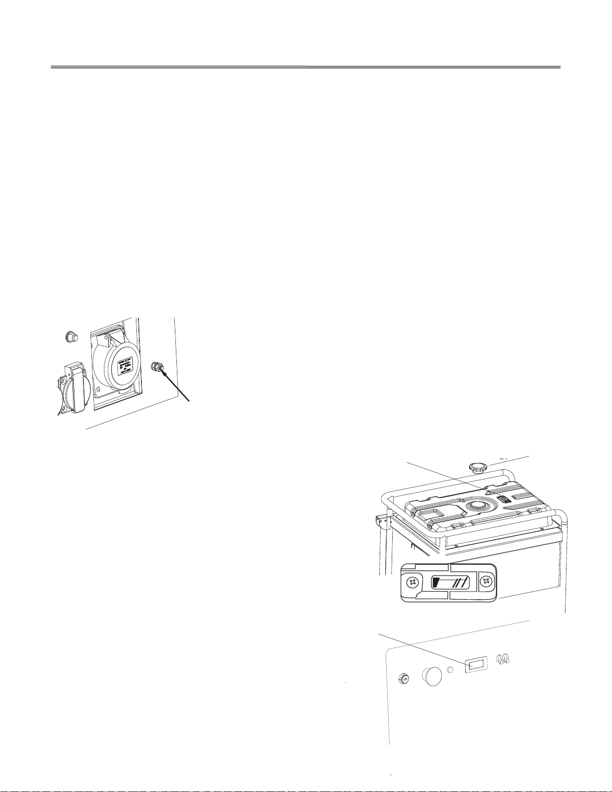
1 Make sure that the AC circuit breaker is in the OFF position. The generator may be hard to
start if a load is connected.
2 Turn the gasoline fuel valve to the "OFF" position.
3 Connect the propane gas hose to the regulator/decompression valve.
4 Connect the propane gas collar to the gas supply and then turn on the propane gas supply.
5 Press the button on top of the pressure release valve down two or three times.
OPEN
CHOK E KNOB
12
Page 14

6 The choke operates differently on propane gas.
a. If the engine is warm (the unit was run recently) start with the choke half open.
i. Wait 30 seconds and then push the choke lever all the way to the "OPEN" position.
b. If the engine is cold (the unit was not run recently) start with the choke "OPEN".
7 Turn the engine key switch to the START position and hold it there for 5 seconds, or until the
engine starts.
Operating the starter motor for more than 5 seconds can damage the motor. If the engine fails to start,
release the switch and wait 10 seconds before operating the starter again.
If the speed of the starter motor drops after a period of time, it is an indication that the battery should
be recharged.
When the engine starts, allow the engine switch to return to the ON position.
Stopping the Engine
In an emergency:
To stop the engine in an emergency, move the engine switch to the OFF position.
In normal use:
1 Turn the AC circuit breaker to the OFF position. Disconnect DC battery charging cables.
2 Turn the engine switch to the OFF position.
3 Turn the off the propane gas supply.
Connect to propane
assup
p
l
g
y.
Decompression
Valve / Regulator
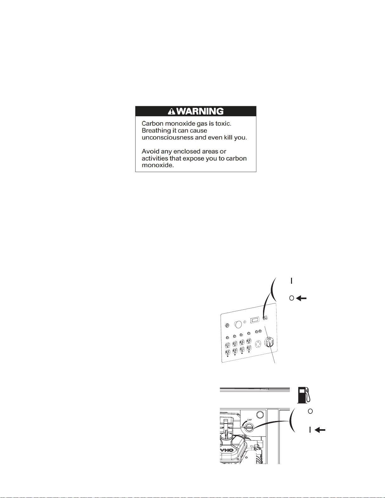
STOPPING THE ENGI NE
To stop the engine in an emergency, simply turn the engine switch to the OFF position. Under normal conditions, use
the following procedure.
ON
1.
Move the circuit breaker to the OFF p osition.
OFF
CIRCU I T
BREA K E R
Page 15

TurntheengineswitchtotheOFFposition
2.
OFF
ON
ENGINE SWICH
.
STAR
OPERATION
2-1.
Turn th e fuel valve lever to the OFF position.
4.
ON
OFF
FUEL VALVE LEVER
4.
AC OPERATION
If an appliance beings to operate abnormally, becomes sluggish or stops suddenly, turn it off immediately. Disconnect the
appliance, and determine whether the problem is in the appliance or the rated load capacity of the generator has been
exceeded.
Substantial over loading may damage the generator.Marginal over loading may shorten the service life of the generator.
NOTICE
Receptacle
AC
1. Start the engine (see page 11).
2. Switch ON the circuit breaker.
CIRCUIT
BRE AK ER
ON
OFF
3. Plug in the appliance.
Most motorized appliances require more
than their rated wattage for startup.
13
Page 16

OPERATION
AC Applications
Before connecting an appliance or power cord to the generator:
Make sure that it is in good wo rking order. Faulty appliances or Power cords can c reate a poten tia l for electrical
shock.
If an app liance begins to operate abnormally, becomes slugg ish, or stops suddenly, turn it
off immediately. Disconnect the appliance, and determine w hether the problem is the appliance or the rated
load capacity of the generator has been exceeded.
Make sure that the electrical rating of the tool or appliance does not exceed that of the generator. Never exceed
the maximum power rating of the generator. Power levels between rated and maximum may be used for no more
than 30 minutes.
NOTICE
Substantial overloading will open the circuit breaker. Exceeding the time limit for max imum power ope ration or slightly
overloading the generator may not swit ch the circuit breaker OFF, but will shorten the service life of the gen erator.
Limit operation requiring maximum power to 30 minutes.
Maximum power is:
60Hz 13 kVA
For continuous operation (longer than 30 minutes), do no t exceed the rated
power. Rated power is:
60Hz 12 kVA
14
Page 17

OPERATION
The total power requi rements (VA) of all app liances conn ec ted m ust be considered. Appliance
and power tool manufacturers usually list rating information near the model number or serial number.
STANDBY POWER
Connect ions to a Building ’s Elect rical System
Your generator can supply power to a building ’s electrical system. If th e generator will be used as
an
alternative
to utility company power, an isolation switch must be installed to disconnect the utility lines from
the building when the generator is connected. Installation must b e perform ed by a qualified electrician and must
comply with all applicable laws and electrical codes.
In some areas, generators are required by law to be registered with local utility compa nies. Check local regulations for
proper registration and use procedures.
System Ground
THIS generators have a system ground that c onnects the gen erator frame comp onents to the ground term inals in the
AC output receptacles. The system ground is not connected to the AC neutral wire. If the generator is
tested with a receptacle tester, it will not show the same ground circuit c ondition as for a home receptacle.
In some areas, generators are required to be registered with loca l utility companies.
If the generator is used a t a construction site, there may be additional regula tions that must be observed.
15
Special Requirements
Page 18

SERVICING YOUR GENERATOR
THE IMPORTANCE OF MAINTENANCE
Good maintenance is essential for safe, economical, and trouble free operation. It will also help reduce air pollution.
To help you properly care for yo ur generator, the following pages include a maintenanc e schedule, routine insp ection
procedures, and simple maintenanc e procedures using basic hand tools. Other service tasks that are mo re difficu lt or
require
special tools are best handled by professionals and are normally performed by a THIS
technician or other qualified mechanic.
The maintenance schedule applies to normal
operating condition s. If you operate your generator under
unusual conditions, such as sustained high load or high temperature operation, or use it in dusty
conditions, consult your servicing dealer for recommendations applicable to your individua l needs and use.
Remember that your servicing dealer knows your generator best and is fully equipped to maintain and repair it.
MAINTENA NCE SAFETY
Some of the most important safety precautions follow. However, we cannot warn you of every conceivable hazard that
can arise in performing maintenance. Only you can decide whether or not you should perform a given task.
Safety Precautions
Make sure the engine is off before you begin any maintenance or repairs. This will eliminate several potential hazards:
Carbon monoxide poisoning from engine exhaust.
Be sure there is adequate ventilation whenever you operate the engine.
Burns from hot parts.
Let the engine and exhaust system cool before touching.
Injury from moving part s.
Do not run the engine unless instructed to do so.
16
Page 19

SERVICING YOUR GENERATOR
Read the instructions before you begin, and make s ure you have the tools and skills required.
To reduce the possibility of fire or explosion, be careful when working around gasoline. Use only a nonf lammable
solvent, not gasoline, to clean parts. Keep cigarettes, spa rk s, and flames away from all fuel related parts.
E
.
m
r
ol
en
MAINTEN A NCE SCHEDUL
*
NOTE: (*) Replace thepaper element only.
(1) Servi c e more frequen tly when used industry areas
(2) These items should be serv ic ed by your servicing dealer, un less you have the proper too l s and are
echanically p roficient. Refer to our shop manual for service procedures.
(3) For commercial use, log hou
Failure to f
REFUELING
With th e
low this maintenance schedule could result in nonwarrantable failures.
gine stopped, check the fuel gauge. Refill the fueltank if the fuel level is low.
s of o peration to determine propermaintenance intervals.
17
Page 20

SERVICING YOUR GENERATOR
FUEL GAUGE
EMPTY FULL
Refuel in a well ventilated a rea before starting the engine. If the engine has b een running, allow
FUEL TAN K
it to cool. Refuel
carefully to avoid spilling fuel. Do not fill the fuel tank above the upper limit mark (red) on the fuel strainer.
Never refuel the engine inside a building where gasoline fumes may reach flames or sparks. Keep gasoline away from
appliance pilot lights, barbecues, electric appliances, power tools, etc.
Spilled fuel is not only a fire hazard, it causes environmental damage. Wipe up spills immediately.
NOTICE
Fuel can damage paint and pla stic. Be careful not to spill fuel when filling you r fuel tank. Damage caused by spilled fuel
is not covered under warranty.
NOTE:
Gasoline spoils very quickly depending on factors suc h as light, exposure, temperature and time.
In worst cases, gasoline can be contaminated wit hin 30days.
Using contaminated gasoline can seriously damage the engine (carburetor clogged, valve stuck).
Such damage due to spoiled fuel is disallowed f rom coverage by the warranty.
To avoid this please strictly follow these recommendations:
On ly use specified gasoline .
Use fresh and clean gasoline.
To slow deterioration, keep gasoline in a certified fuel container.
If long storage (more than 30 days) is foreseen, drain fuel tank and carburetor (see page27).
FUEL RECOMMENDATIONS
Use automotive unleaded gasoline with a Research Octane Number of 91 or higher (a Pump Octane Number of 86 or
higher).
Never use stale or contam inated gasoline or an oil/gasoline mixture.
Avoid getting dirt or water in the fuel tank.
18
Page 21

SERVICING YOUR GENERATOR
Gasolines Containing Alcohol
If you decide to use a gasoline containing a lc ohol (gasohol), be sure it’s octane rating is at least as high as that
recommended by THIS. There are t wo types of ‘ ‘gasohol’’: one containing ethanol, and the other containing methanol.
o not use gasohol that contains more than 10% ethanol. Do not use gasoline containing methanol (methyl or wood
D
alcohol) that does not also contain cosolvents and corrosion inhibitors for methanol. Never use gasoline containing more
than 5% methanol, even if it has c osolvents and corrosion inhi bitors.
NOTE:
Fuel system damage or engine performance problems resulting from the use of fu els that contain alcohol is not
covered under the warranty.
THIS cannot endorse the use of fuels containing methanol sinc e evidence of their suitability is as yet incomplete.
Before buying fuel from an unfamiliar station, try to find out If the fuel contains alcohol, if it does, confirm the type
and p er centage of alcohol us e d.
If you n otice any undesirable operating symptoms while using a gasoline that contains alcohol, or one that you think
contains alcohol, switch to a gasoline that you know does not contain alcohol.
ENGINE OIL LEVEL CHECK
Check the engi ne oil level with the generator on a level surface and the engine stopped.
1. Remove the oil level dipstick and wipe it clean.
2. Fully insert
t
he dipstick, then remove it to check the oil level.
3. If the level is near or below the lower limit mark on the dipstick, open the
maintenance cover to access the oil filler cap. Remove the oil filler cap, and
fill with the recommended oil to the upper limit mark.
4. Reinstall the oil level dipstick and f iller cap.
OIL FILLER CAP
OIL LEVE L
DIPS TI CK
The Oil Alert system will automatically stop th e engine before the oil level falls below safe limits. However, to avoid the
inconvenience of an unexpected shutdown, check th e oil level regularly.
19
Page 22

SERVICING YOUR GENERATOR
ENGINE OIL CHANGE
Drain the oil while the engin e is warm to assure rapid and complete draining.
1. Placethegeneratoronwoodenblockstomakespaceforplacingasuitablecontainer.
2. Open the maintenance ov er to access the oil filler cap.
3. Remove the oil filler cap, oil drain bolt and sea ling washer, and drain the oil in to the container.
4. Install a new sealing washer and the oil drain bolt, and tighten the bolt securely.
5. Refill to the upper limit mark on the dipstick with the recommended oil. Tighten the oil filler cap securely .
Engine oil capacity:
oil filter replacement:
With
Approximately 1.6L
Wash your hands with soap and water after handling used oil.
OIL FILLER CAP
OIL DRAIN BOLT
Please dispose of used motor oil in a manner tha t is compatible with the environmen t. We suggest
you take it in a sealed container to your local service station or recycling center for reclamation. Do not throw it in the
trash, p our it on
the ground, or pour it down a drain.
OIL FILTER CHANGE
1. Drain the engi ne oil, and tighten the drain bolt securely.
2. Remove the oil filter, and drain the oil in to a suitable container.
D iscard the used oil filter.
3. Clean the filter moun ting base, and coat the O-ring of the new oil filter with clean engine oil.
4. Screw on the new oil filter by hand, until the O-ring contacts the filter mounting base, and then use an
oil filter socket tool to tighten the filter an add itional 7/8 turn.
TORQUE: 12N·m (1.2kgf·m)
5. Refill the crankcase with the specified amount of the recommended Oil (see pages 36 and 38). Reinstall the oil filler
cap.
6. Start the engine and check for oil filter leaks.
7. Stop the engine, and check the oil level as described on
page 21. If n ecessary, add oil to the upper limit mark on
the dipstick.
OIL FILLER
20
O-RING
Page 23

SERVICING YOUR GENERATOR
ENGINE OIL RECOMMENDATIONS
Oil is a major factor affecting engine performance and service life.
Use 4-st roke automotive detergent oil that meets or exceeds the requirements for API service category SE or later (or
equivalent).
SAE 10W-30 is recommended for general use. Other viscosities shown in the chart
may be used when the average temperature in your area is within the recommend ed
range.
The SAE oil viscosity an d service category are on the API label on the oil container.
CLEANER SERVICE
AIR
Release four latch tabs from the air cleaner cover, and remove the cover.
1.
2. Foam air f ilter:
Remove the foam air filter from the air cleaner housing.
a.
b. Check the foam air filter to be sure it is clean and in good condition.
Replace the foam air f ilter if it is damaged.
c. Reinstall the foam air filter in the air cleaner housing.
3. Paper air filter:
If the paper air filter is dirty, replace it with a new one. Do not clean the pa per air filter.
4. Reinstall the air cleaner cover.
5. Close the maintenance cover.
FOAMAIRFILTER
AIR CL EAN E R COVER
PAP E R AIR FI LTE R
AIR CLEAN E R COVE R
21
Page 24

SERVICING YOUR GENERATOR
NOTICE
Operating the engine without an air filter, o r with a damaged air filter, will allow dirt to enter the engine, causing rapid
engine wear.
FOAM A IR FILTER CLEANING
A dirty foam air filter will restrict air flow to the carburetor, reducing engine performance. If you operate th e generator
in very dusty areas, clean the foam air filter more frequently than specified in the Main tenance Schedule.
1. Clean the fo am air filter in warm soapy water, rinse, and allow to dry thoroughly, or clean in non-flammable solvent
and allow to dry.
2. Dip the foam air filter in clean engine oil, then squeeze out all excess oil. The engine will smoke when started if too
much oil is left in the foam air filter.
SEDIMENT CU P CLEANING
1. Turn the fuel valve lever to the OFF position, then remove the Sediment cup and the O-ring. Discard the O-ring.
2.
Wipe dirt from the air cleaner housing and cover using a moist rag. Be careful to prevent dirt from entering the air
duct t hat leads to the carburetor.
22
Page 25

SERVICING YOUR GENERATOR
2. Clean the sediment cup in nonflammable solvent, and dry them thoroughly.
3. Install the new O-ring and sediment cup, and tighten the sediment cup securely.
4. Make sure there is no fu el leakage.
SPARK PLUG SERVICE
Recommended spark plugs: F7TC
NOTICE
An incorrect spark plug can cause engine damag e.
If the engine is hot, allow it to cool before servicing the spark plug.
1. Disconnect the spark plug caps, and remove any dirt f rom around the spark p lu g area.
2.
Remove the spark plugs with a 180mm spark plug wrench
(commercially a
vailable).
3. Inspect the spark plugs. Replace them if the electrodes are worn or if the insulator
is cracked, chipped, or fouled.
4. Measure the spark plug electrode gap with a wire type feeler gauge. Correct the gap, if necessary, by carefully
bending the side electrode.
The gap sh ould be: 0.7 -- 0.8m m
5. Make sure that the spark plug sealing washers are in good condition, and th read the spark plug in by hand tprevent
cross threading.
6. After the spark plugs seat, tighten with a 21mmsparkplugwrenchto compress the washer.
If reinstalling a used spark plug, tighten 1/81/4 turn af ter the spark plug seats.
If installing a new spark plug, tighten 1/2 turn after the spark plug seats.
23
0.7 - 0.8mm
Page 26

SERVICING YOUR GENERATOR
NOTICE
A loose spark plug can overheat and damage the engine. Over tighten ing the spark plug can damage the threads in the
cylinder head.
7. Attach the spark plug caps.
BATTERY SERVICE
Your generator’s engine charging system charges the battery while the en gine is running. However, if the gen erator is
only u sed periodically, the battery must be cha rged monthly to maintain the battery service life.
Emergency Procedures
Eyes -- Flush with water from a cup or other container for at least fifteen minutes. (Water under pressure can dama ge
the eye.)
Immediately call a physician.
Skin -- Remove contaminated clothing. Flush the skin with large quantitie s of w ater. Call a physician immediately.
Swallowing -- Drink water or milk. Call a physician immediately.
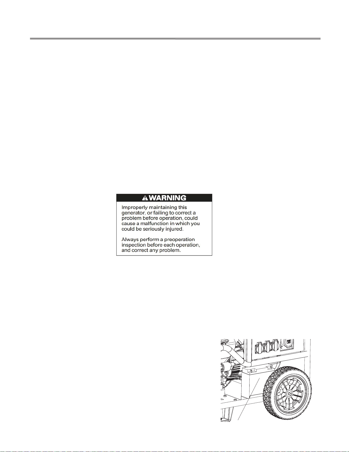
Battery Removal
WARNING: Battery posts, terminals, and related accessories contain
lead and lead compound s. Wash hands after handling.
1. Remove the negative (-) cable from the
battery negative (-) terminal first, and
then remove the positive () cable from
the battery positive (+) terminal.
2. Remove the flange nuts, and remove the battery set plate.
3. Remove the battery from the battery tray.
24
+
_
Page 27

SERVICING YOUR GENERATOR
This symbol on the battery means that this product must not be treated as household waste.
NOTE:
An improperly dis posed of battery can be harmful to the environment
and hum an hea lth.
Always confirm local regulations for battery disposal.
Battery Charging
The battery is rated at 30 .0Ah (ampere hours). Charging current should equal 10% of the battery’s ampere hour rating.
1. Connect the ba ttery charger following the manufac tu rer ’s instruction s.
2. Charge the battery.
3. Clean the outside of the battery and the battery compartment with a solution of baking soda and water.
Battery Installation
1. Install the battery into the generator.
2. Connect the battery positive (+) cable to the battery positive (+ ) terminal first, and tighten the bolt securely.
3. Slide the battery boot over the positive (+) cable and terminal .
4. Connect the battery negative (-) cable to the battery negative (-) terminal, and tighten th e bolt securely.
25
Page 28

STORA GE
STORAGE PREPARATION
Proper storage preparation is essential for keeping yo u r generator trouble free and looking good. The following steps
will help to keep rust and corrosion from impairing your generator ’s function and appearance, and will make the engine
easiertostartwhenyouusethegeneratoragain.
Cleaning
Wipe the generator with a moist cloth. After the generator has dried, touc h up any damaged paint, and coat other areas
that may rust with a light film of oil.
Fuel
Gasoline will
oxidize and deteriorate in storage. Old gasoline will cause hard starting, and it leaves gum deposits
that clog th e fuel system. If the gasoline in your generator deteriorates during storage, you may need to have the
carburetor and other fuel system components serviced or replaced.
NOTE:
Gasoline spoils very quickly depending on factors suc h as light exposure, temperatu re and time.
In worst cases, gasoline can be contaminated wit hin 30days.
Using contaminated gasoline can seriously damage the engine (carburetor clogged, valve stuck).
Such damage due to spoiled fuel is disallowed f rom coverage by the warranty.
To avoid this please strictly follow these recommendations:
Only use specified gasoline .
Use fresh and clean gasoline.
To slow deterioration, keep gasoline in a certified fuel container.
If long storage (more than 30days) is foreseen, drain fuel tank and carburetor (see page 27).
You can extend fuel storage life by adding a gasoline stabilizer that is formulated for that purpose, or you can avoid fuel
deterioration problems by draining the fuel tank and carburetor.
Adding a Gasoline Stabilizer to Extend Fuel Storage Life
When addin g a gasoline stabilizer, fill the fuel tank with fresh gasoline. If only partially filled, air in the tank will promo te
fuel deterioration during storage. If you keep a container of gasoline for refueling, b e sure that it contains only
fresh gasoline.
1. Add gasoline stabilizer following the manufacturer’s instructions.
2. After adding a gasoline stabilizer, run the engine outdoors for 10 minutes to be sure that treated gasoline has replaced
the untreated gasoline in th e carburetor.
3.
Stop the engine, and turnthefuelvalvelever to the OFF position.
26
Page 29

STORA GE
STORAGE PROCEDURE
1. Drain the fuel tank and carburetor.
a.
Unscrew the fuel tank cap, remove the fuel filter, and empty the
fuel tank into an approved gasoline container. We recommend
using a commercially available gasoline hand pum p to empty
the tank. Do not use an electric pump. Reinstall the fuel filter
and th e fuel tank cap.
b. Pull out the ca rburetor drain tube end under th e fan cover of the engine , and plac e it in a suitable co ntainer.
c.
Loosen the carburetor drain screw.
d.
Drain the gasoline from the ca rburetor into the container.
e. Tighten the carburetor drain screw securely.
2. Change the engine oil (refer to page 20).
3. Remove the spark plugs (see page 23).
4. Pour a table spoon (5-10cc) of clean engine oil into each cylinder.
5. Turn the engine for a few seconds by turning the engine switch to the START position to distribute the oil in
the cylinders.
6.
Reinstall the spark plugs.
7. Remove the battery and store it in a cool, dry place. Recharge it once a month.
8. Cover the generator to keep out dust.
27
Page 30

STORAGE
STORAGE PRECAUTIONS
If your generator will be stored with ga solin e in the fuel tank and carburetor, it is important to reduce the hazard of
gasoline vapor ignition.
Select a well ventilated storage area away from any appliance that operates with a flame, such as a furnace, water heater, or
clothes dryer. Also avoid any area with a spark producing electric motor, or where power tools are operated.
If possible, avoid storage areas with high humidity, because that promotes rust an d corrosion.
Unless all fuel has been drained from the fuel tank, leave the fuel valve lever in the OFF position to redu ce the possibility of
leakage.
Place th e generator on a level surface. Tilting can cause fu el or oil leakage.
With the engine and exhaust system cool, cover the generator to keep out dust. A hot engine and exhaust system can
ignite or melt some materials.
Do not use sheet plastic as a dust cover. A nonporous cover will trap moisture around the generator, promoting rust and
corrosion.
REMOVAL FROM STORAGE
Check your generator as described in the BEFORE OPERATION chapter of this manual.
If the fuel was drained during to rage preparation, fill the tank with fresh gasoline. If you keep a container of gasoline
for refuelin g, b e sure that it contains only fresh gasoline. Gasoline oxidizes an d deteriorates overtime,
causing hard starting.
28
Page 31

TRANSPORTING
If the generator has bee n running, allow the engine to coo l for at least 15 minutes before loadin g the generator on the
transport vehicle. A hot engine an d exhaust system can burn you and ca n ignite some materials.
Keep the generator level when transporting to reduce the possibility of fuel leakage. Move the fuel valve lever to the
OFF position.
When using ropes or tied owns traps to secure the generator for transportation, be s ure to only use the f rame bars as
attachment points. Do not fasten ropes or straps to any portions of the generator body.
29
Page 32

TAKING CARE OF UNEXPECTED PROBLEMS
hoke OPEN.
ove to CLOSED
toffuel.
efuel (p.18).
ad fu el; generator stored without
reatingordraininggasoline,orrefueled
bad gasoline.
rain fuel tank and carburetor
p.27).Refuel with fresh
asoline(p.18).
park plug wet with fuel (flooded engine
ry an d reinstall spark plug.
30
Engine Will Not Start Possible Cause Correction
1. Check control positions
2. Check fuel
3. Check engine oil level.
4. Remove and inspect spark
plug.
5. Take generator to an
authorized THIS
servicing dealer, or refer
to shop manual.
Fuel valve lever OFF. Turn lever ON.
C
Engine switch OF F. Turn engine switch to ON.
Ou
B
t
with
Low oil level caused Oil Alert to stop
engine.
Spark plug faulty, fouled, or improperly
gapped.
S
Fuel filter restricted, carburetor
malfunction, ignition malfu n c tio n, valves
stuck etc.
M
R
D
(
g
Add oil (p.20). Turn engine switch to
OFF and restart the engine.
Gap, or replace spark pl ug (p.23).
). D
Replace or repair faulty components
as necessary.
Engine Lacks Power Possible cause Correction
1. Check air filter. Air filter restricted.
Bad fuel; generator stored without
2. Check fuel.
3. Take generator to an
authorized THIS
servicing dealer, or refer
to shop manual.
treating or draining gasoline, or refueled
with bad gasoline.
Fuel filter restricted, carburetor
malfunction, ignition malfu n c tio n, valves
stuck etc.
Clean or replace air filter (p.22)
Drain fuel tank and carburetor (p.27).
Refuel with fresh gasoline
(p.18)
Replace or repair faulty components
as necessary.
Page 33

TAKING CARE OF UNEXPECTED PROBLEMS
31
NoPoweratthe
AC Receptacles
1. Check circuit b rea ker.
2. Check the power tool or
applianc e at a known
good AC power source.
3. Take generator to an
authorized THIS
servicing dealer, or refer
to shop manual.
Possible cause Correction
Circuit breaker left in the O FF position
after starting.
Faulty power tool or appliance.
Faulty generator.
Switch circuit breaker ON.
Replace or repair power tool or
appliance. Stop and restart the engine.
Replace or repair faulty components as
necessary.
Page 34

TECHNICAL INFORMA TION
SERIAL N U MBER LOCATION
ENGIN E SERIA L NU MB E R
DRAI N O I L LINE
Recordtheengineandframeserialnumbersanddatepurchasedinthespacesbelow.Youwillneedthisserialnumber
when ordering parts, and when making technical or warranty inquiries.
Engine serial number:_______________________ ____________ __
Frame serial number:_____________________________________
Date purchased:_________________________ _________________
CARBURETOR MODIFICATION FOR HIGH ALTITUDE OPERATION
At high a ltitude, h e standard carburetor air-fuel mixture will be too rich. Performanc e will decrease, and fuel consumption
will increa se. A very rich mixture will also foul the spark plu gs and cause hard starting.
Operation at an altitud e that differs f rom that at which this engine was certified, for extended periods of time, may increase
emissions.
High altitude performance can be improved by specific modifications to the carburetor. If you always operate your
generator at altitudes above 1,500 meters,
modification.
Even with carburetor modification, engine horsepower will decrease about 3.5% for each 300 meter increase in altitude.
h
ave your authorized THIS servicin g dealer perform this c arburetor
NOTICE
When the carburetor has been mod ified for high altitude operatio n, the air/fuel mixture will be too lean for low altitude use.
Operation at altitudes below 1,500 meters with a mod if ie d carbure tor may cause the engine to ove rheat and result
in serious engine damage. For use at
Low altitud es, have your servicing dealer return the carburetor to original factory specifications.
32
Page 35

TECHNICAL INFORMATION
SPECIFICATIONS
Dimensions
Model
Length
Width
Height
Dry mass(w eight)*
*with battery
XP15000E
870
mm
588
mm
mm
26
7
215kg
Engine
Model
Engine Type 4-stroke,overheadvalve,2cylind er
Displacement 7
Bore & Stroke
Cooling System Forced air
Ignition System Transistorized magneto ignition
Oil Capacity With oil filter replacement approximatly 1.5L
Fuel Tank Capacity 40L
Spark Plug F7TC(NHSPLD)
Battery 12V/
DHT720E
13cc
*71mm
0
8
21
AH
Generator
Model
Single-phase
Rated voltage 240V
60Hz
0A
AC output
Rated frequency
Rated Ampere 5
Rated output 12.5kW
Maximum output 15kW
Power factor
Tune up Specifications
ITEM SPECIFICATION MAINTENANCE
Spark plug gap 0.7-0.8mm Refer to page: 25
Valve clea rance(cold) IN:0.0
Other specifications No other adjustments needed.
Specifications may vary according to the types, and are subject to change without notice.
8-0.12mm EX:0.13-0.17mm See your authorized dealer
.8
0
33
Page 36

WIRING DIAGRAM
SINGLE PHASE DIAGRAM XP1500E
TECHNICAL INFORMATION
34
Page 37

Page 38

Product Support Product Information, Application, Service Info & Warranty Questions
Please email us at support@duromaxgenerators.com
or call (800) 629-3325 Monday – Friday 6:00 am – 6:00 pm (PST)
 Loading...