

DURMA CNC User Manual
CNC ADVANTAGE
USER GUIDE
CNC_ADVANTAGE_UserGuide_GB_V100525

REVISION LIST
V100525 : 25/05/2010
First release.
PAGE 1

CONTENTS
ABBREVIATIONS ................................................................................................................... 6
GENERAL SPECIFICATIONS ................................................................................................ 7
FUNCTIONS OF KEYS ........................................................................................................... 8
CONTROL PANEL ............................................................................................................................ 8
NUMERICAL KEYS ........................................................................................................................... 8
PAGE SELECTION KEYS ................................................................................................................ 8
OPERATING MODES and MOVEMENT KEYS ............................................................................... 9
FUNCTION KEYS ............................................................................................................................. 9
COMMAND KEYS ............................................................................................................................. 10
CURSOR KEYS ................................................................................................................................ 11
CALIBRATION (INDEXING) .................................................................................................... 12
PROGRAMMING PAGES ....................................................................................................... 13
RECIPE PAGE .................................................................................................................................. 13
EXPLANATION OF THE RECIPE PAGE FIELDS ............................................................................ 15
PCSS LAZERSAFE PAGE ................................................................................................................ 16
EXPLANATION OF THE PCSS LAZERSAFE PAGE FIELDS ......................................................... 17
PROFILE PAGE ................................................................................................................................ 18
EXPLANATION OF THE PROFILE PAGE FIELDS .......................................................................... 19
ORDER PAGE .................................................................................................................................. 20
EXPLANATION OF THE ORDER PAGE FIELDS ............................................................................ 20
SAMPLE-1 ......................................................................................................................................... 21
ENTER A PROFILE ................................................................................................................................. 21
DEFINITION OF THE BENDING ORDER ............................................................................................... 22
EASY WORKING PAGE ......................................................................................................... 24
PROGRAM MANAGEMENT PAGES ...................................................................................... 25
LIST OF PROGRAM ......................................................................................................................... 25
SEARCHING PROGRAM BY CRITERIA .......................................................................................... 26
CALLING PROGRAM ....................................................................................................................... 27
SAVING PROGRAM ......................................................................................................................... 27
DELETING PROGRAM ..................................................................................................................... 28
DELETING ALL PROGRAMS ........................................................................................................... 28
TOOL LISTING and PROGRAMMING .................................................................................... 29
LIST OF PUNCHES / DIES ............................................................................................................... 29
EXPLANATION OF THE FIELDS ..................................................................................................... 30
PUNCH .................................................................................................................................................... 30
DIE ........................................................................................................................................................... 30
PROGRAMMING PUNCH ................................................................................................................. 31
CREATE NEW PUNCH BY MODIFYING AN EXISTING ONE ........................................................ 32
MODIFY AN EXISTING PUNCH ....................................................................................................... 32
DELETING PUNCH ........................................................................................................................... 32
DELETING ALL PUNCHES .............................................................................................................. 32
PROGRAMMING, MODIFYING, DELETING etc. OF DIE ................................................................ 33
USB MEMORY BACKUP PAGE ............................................................................................. 34
ERROR / WARNING MESSAGES .......................................................................................... 35
STOPPING and LEAKAGE TEST MESSAGES ............................................................................... 37
PAGE 2

PARAMETERS ....................................................................................................................... 38
GENERAL PARAMETERS ............................................................................................................... 38
01 Display Unit [ - ] .................................................................................................................. 38
02 Display Mode [ - ] .................................................................................................................. 38
03 Display Dimension [ - ] ....................................................................................................... 39
04 Language Selection [ - ] ..................................................................................................... 39
05 Contrast [ -- ] ........................................................................................................................ 39
06 F2 Password [ ---- ] ............................................................................................................. 40
07 F3 Password [ ---- ] ............................................................................................................. 40
08 Profile and Order Page Enable [ - ] ............................................................................. 40
09 Communication BaudRate [ - ] ............................................................................................ 40
Bending Counter [ -------- ] ............................................................................................ 41
Working Hour [ ------ ] ....................................................................................................... 41
ANALOG PARAMETERS .................................................................................................................. 42
20 Rated Capacity (T) [ ---.- ] ............................................................................................ 42
21 Pressure 0%,25%,50%,75%,100% [ --- ] ........................................................................... 42
22 Pressure (%) [ -- ] ........................................................................................................... 43
23 High Speed Pressure
24 High Speed Deceleration Pressure
25 Low Speed Minimum Pressure
26 Low Speed Deceleration Minimum Pressure
27 Pressure Decompression (%) [ -- ] ................................................................................. 44
28 Pressure Deceleration/Acceleration Time [ -.-/-.- ] ........................................... 44
30 Crowning Module Enable [ - ] ............................................................................................ 45
31 Stop Distance [ -- ] ............................................................................................................. 45
32 Position Tolerance [ -- ] ................................................................................................... 45
33 Crowning 0%,25%,50%,75%,100% [ ---- ] ......................................................................... 46
BEAM PARAMETERS ...................................................................................................................... 47
40 Encoder Resolution [ ---.--- ] ........................................................................................ 47
41 Resolution Inch/Metric [ -/- ] ........................................................................................ 47
42 Change Counting Direction [ Y1 – Y2 - ] ..................................................................... 47
43 Final Approach Distance [
44 Low Speed Deceleration Ramp Distance [ --.-- ] ...................................................... 48
45 Low Speed Distance [ --.-- ] ............................................................................................ 48
46 High Speed Deceleration Distance [ --.-- ] .............................................................. 48
47 Maximum Bending Speed (mm/s) [ -- -- ] .............................................................. 49
48 Minimum/Maximum Limits [ ----.--/----.-- ] .............................................................. 49
49 TDP Minimum [ ---.-- ] ......................................................................................................... 49
50 Deceleration Ramp Distance [
51 Acceleration Ramp Distance [
52 Offset Voltage [ Y1 --.- Y2 --.- ] ............................................................................... 50
53 Final Approach Voltage [ -.- -.- ] ....................................................................... 50
54 Low Speed Voltage [
55 High Speed Deceleration Voltage [
56 High Speed Voltage [
57 Indexing Voltage [ -.- ] ..................................................................................................... 51
58 Decompression Voltage [ -.- ] .......................................................................................... 51
59 Speed Change Delay (s) [ -.- ] ........................................................................................ 52
60 Speed Change Pressure Delay (s) [ -.- ] ..................................................................... 52
61 Regulation Delay (s) [ -.- ] ............................................................................................ 52
62 Servo-Valve Delay (s) [ -.- ] .......................................................................................... 52
63 Decompression Time (s) [ -.- ] ........................................................................................ 52
64 Synchronization Limit Y [ --.-- ] ................................................................................. 53
65 Synchronization Gain High Speed [
66 Next Cycle Starting Point [ - ] ...................................................................................... 53
67 Mute Distance Above Material [ --.-- ] ....................................................................... 53
68 Index Position [ Y1 ----.-- Y2 ----.-- ] .................................................................. 54
69 Reference Position [ Y1 ----.-- Y2 ----.-- ] .......................................................... 54
95 Acceleration Distance High Speed [ MAX ---.-- ] ................................................... 55
96 Stopping Time (s) [ MAX -.-- ] ........................................................................................ 56
97 Stopping Distance [ MAX --.-- ] ...................................................................................... 56
98 Leakage Measurement Time (s) [ MAX -.- ] .................................................................. 56
99 Cylinder Leakage [ MAX --.-- ] ........................................................................................ 56
(%) [ -- ] .................................................................................... 43
(%) [ -- ] ........................................................ 43
(%) [ -- ] ..................................................................... 43
(%) [ -- ] ......................................... 43
-.-- -.-- ] ................................................................ 48
--.-- --.-- ] ...................................................... 49
--.-- --.-- ] ...................................................... 49
-.- -.- ] ................................................................................. 50
-.- ] ................................................................ 50
-.- -.- ] ............................................................................... 51
-- -- BDP -- ] ......................................... 53
PAGE 3

X1 / X2 AXIS PARAMETERS ........................................................................................................... 57
X00 Module Enable [ - ] ............................................................................................................... 57
X01 Encoder Resolution [ ---.--- ] ........................................................................................ 57
X02 Resolution Inch/Metric [ -/- ] ........................................................................................ 57
X03 Minimum/Maximum Position [ ----.---/----.--- ] ...................................................... 58
X04 Calibration Position [ ----.--- ] ................................................................................. 58
X05 Manual Speed Slow/Fast (%) [ ---/--- ] ....................................................................... 58
X06 Positioning Speed (%) [ --- ] .......................................................................................... 59
X07 Calibration Speed (%) [ --- ] .......................................................................................... 59
X08 Final Positioning Speed (%) [ --- ] ............................................................................. 59
X09 Final Positioning Gain [ --/-- ] .................................................................................... 59
X10 Acceleration Ramp Time (s) [ --.- ] ............................................................................. 60
X11 Slow Speed Distance [ --.--- ] ........................................................................................ 60
X12 Deceleration Ramp Distance [ --.--- ] ......................................................................... 60
X13 Stop Distance [ -.--- ] ....................................................................................................... 61
X14 Position Tolerance [ -.--- ] ............................................................................................ 61
120 Safety Distance [ ---.--- ] .............................................................................................. 61
R1 / R2 AXIS PARAMETERS ........................................................................................................... 62
320 Safety Distance [ ---.--- ] .............................................................................................. 62
321 Displacement R [ ---.--- ] ................................................................................................ 62
322 2.Finger Distance X/R [ ---.---/---.--- ] ................................................................ 63
Z1 / Z2 AXIS PARAMETERS ............................................................................................................ 64
620 Safety Distance [ ---.--- ] .............................................................................................. 64
CORRECTION TABLE ...................................................................................................................... 65
800 Material St/Al/Ss/Xx [ --kg/mm2 ] ................................................................................ 65
Springback [ ---.-° ] ........................................................................................................... 66
Thickness [ --.-- ] ............................................................................................................... 66
N Cutting Length [ -.--- ] ................................................................................................ 66
PCSS PARAMETERS ....................................................................................................................... 67
810 LazerSafe Enable [ - ] ......................................................................................................... 67
811 Laser [ - ] ................................................................................................................................. 67
812 Light Curtain [ - ] ............................................................................................................... 67
813 Station Number [ - ] ............................................................................................................. 68
814 Station Configuration [ ----------- ] ......................................................................... 68
815 Working Mode [ ----------- ] ............................................................................................ 69
Operator Selection [ ----------- ] ............................................................................... 69
Station Type [ ----------- ] ............................................................................................ 69
Stop At Mute Point [ - ] ..................................................................................................... 69
Robot [ - ] ................................................................................................................................. 69
BIT13/BIT19 [ -/- ] ............................................................................................................... 69
USB MEMORY PACKUP .................................................................................................................. 70
820 Backup Direction [ >>, << ] .............................................................................................. 70
821 Memory Selection [ -, + ] ................................................................................................... 70
822 Status Messages ........................................................................................................................ 71
MODULE UPDATE ........................................................................................................................... 72
830 Module Selection [X1, X2, R1, R2, Z1, Z2, AN1, Y1Y2, IO1] .............................. 72
831 File Selection [ - ] ............................................................................................................. 72
832 Status Mesaages ........................................................................................................................ 73
MODULE STATUS ............................................................................................................................ 74
Input/Output Module [IO1] ........................................................................................................... 74
BEAM Module [Y1Y2] .......................................................................................................................... 74
Axis Modules [X1, X2, R1, R2, Z1, Z2] ................................................................................. 75
Analog Module [AN1] ........................................................................................................................ 75
PAGE 4

AXIS SAFETY ......................................................................................................................... 76
X-R SAFETY POSITIONING ............................................................................................................ 76
PC COMMUNICATION ........................................................................................................... 77
LCD PANEL SOFTWARE UPDATE ........................................................................................
78
ELECTRICAL CONNECTION DIAGRAMS .............................................................................
LCD PANEL CONNECTION DIAGRAM ........................................................................................... 79
RELAY BOARD CONNECTION DIAGRAM ...................................................................................... 79
INPUT/OUTPUT MODULE (IO1) CONNECTION DIAGRAM ........................................................... 80
BEAM MODULE (Y1Y2) CONNECTION DIAGRAM ........................................................................ 80
AXIS MODULE (AX) CONNECTION DIAGRAM .............................................................................. 80
ANALOG MODULE (AN1) CONNECTION DIAGRAM ..................................................................... 80
79
PAGE 5

ABBREVIATION
BDP Bottom dead point.
TDP Top dead point.
PP Pinch point.
SCP Speed change point from HS to LS.
HS High speed.
LS Low speed.
MP Mute point.
MIN Minimum.
MAX Maximum.
PCSS Pressing Control Safety System.
PAGE 6

GENERAL SPECIFICATIONS
•
RS-232 serial communication for PCSS LazerSafe.
•
Receipe, punch, die, parameter, label and message memory backup to USB or
backup from USB.
•
LCD and module software update with USB.
•
EASY working.
•
RS-232 serial communication for general usage.
•
Synchron control of the BEAM with Y1Y2. (Y1 left, Y2 right)
Encoder input. Maximum counting frequency is 20KHz.
±10V and down/up outputs for BEAM movement.
Programmable INCH and METRICH display resolution separately.
Axes calibration (indexing) for each power on.
•
X1, X2, R1, R2, Z1, Z2 numerical control up to 6 axes.
Encoder input. Maximum counting frequency is 15KHz.
0 - 10V and forward/reverse outputs for axes movement.
Programmable INCH and METRICH display resolution separately.
Axes calibration (indexing) for each power on.
•
Crowning control.
Potentiometer input. Minimum 1Kohm. Resolution 10bit. (Max. 1023)
Forward/reverse outputs for movement.
•
Tonnage (pressure) control.
0 – 10V output for pressure control.
•
Blue-White 320x240 Dot Matrix Graphic LCD display.
•
Easy to use with LIST, PROFILE, PROGRAM and TOOL page by direct access.
•
Allow to select 5 languages : Turkish, English, French, German and Spanish.
•
Allow to use alphanumarical characters on the program and tool code fields.
•
INCH/METRIC conversion.
•
Internal non-volatile memory
- 85 Programs and each program made up 12 steps.
- 32 Punches
- 32 Dies
•
Program Number : 3 numbers
Program Repeat Number : 3 numbers
Program Code Number : 10 numbers or letters
Tool Code Number : 6 numbers or letters
Step Number : 2 numbers
Step Repeat Number : 2 numbers
•
Functions calculated by the CNC
- Shape of the profile which is defined by the user is displayed on the LCD screen at
240x48 pixel resolution.
- Cutting (unfolded) length is calculated according to profile.
- Bending depth is calculated according to bending angle, material and tool selection.
- Bending speed change point.
- Mute point.
- Pinch point.
- Bending force.
- Crowning as a function of the bending force.
•
Functions programmed by the operator
- Following functions are also calculated automatically according to profile and order
values which are defined by the user.
- Target and correction values of the axes.
- Backgauge retraction.
- Top dead point.
- Dwell time.
- Number of the step repetition.
- Number of the program repetition.
PAGE 7
FUNCTIONS OF KEYS
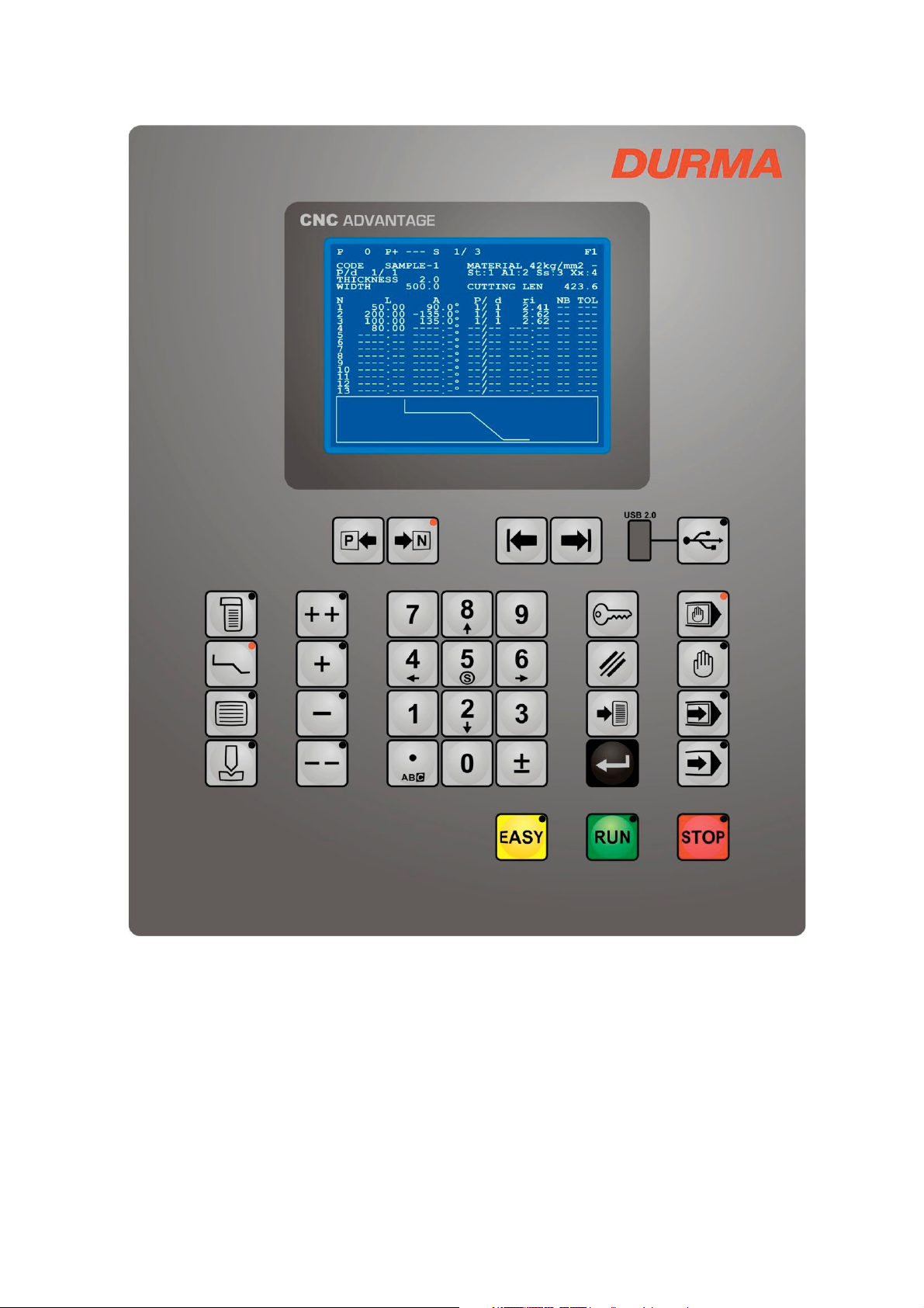
CONTROL PANEL
NÜMERCAL KEYS
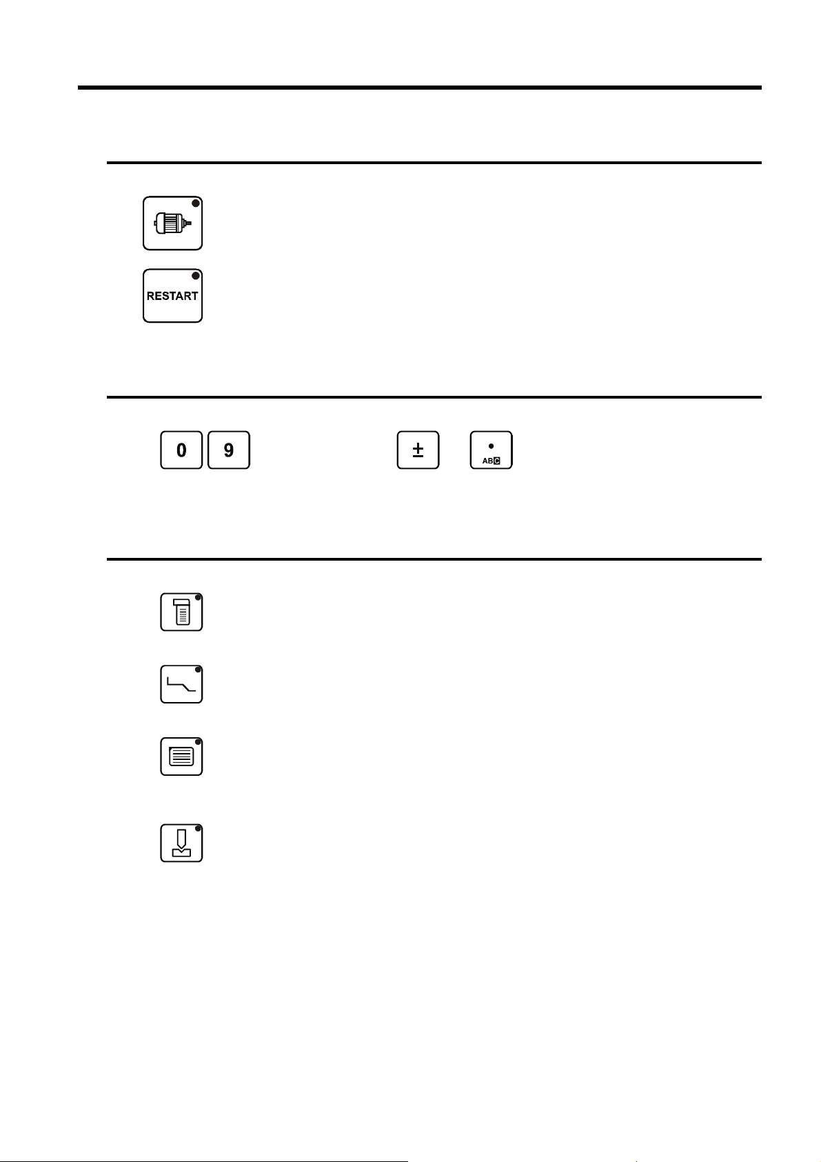
Motor start/stop keys :
Relay is energized during key is pressed. There is a separate input for the light on.
Restart key :
Relay is energized during key is pressed. There is a separate input for the light on.
Numerical keys, and keys are used to introduce numbers or
values into the programmable fields.
PAGE SELECTION KEYS
Program List Key
Double function key.
Pressing the key once displays the list of programs in the memory.
Pressing the key again displays the search for programs by criteria page.
Create a Profile Key :
Double function key.
Pressing the key once displays all values to create a profile.
Pressing the key again displays bending order of the created profile.
Program Key
Triple function key.
Pressing the key once displays all data related positioning with actual values.
Pressing the key second time displays some data in large characters.
Pressing the key third time displays values and status of the PCSS.
Tool Key
Double function key.
Pressing the key once displays the list of punches and dies in the memory.
Pressing the key again displays all data related programming of punch and die.
PAGE 8
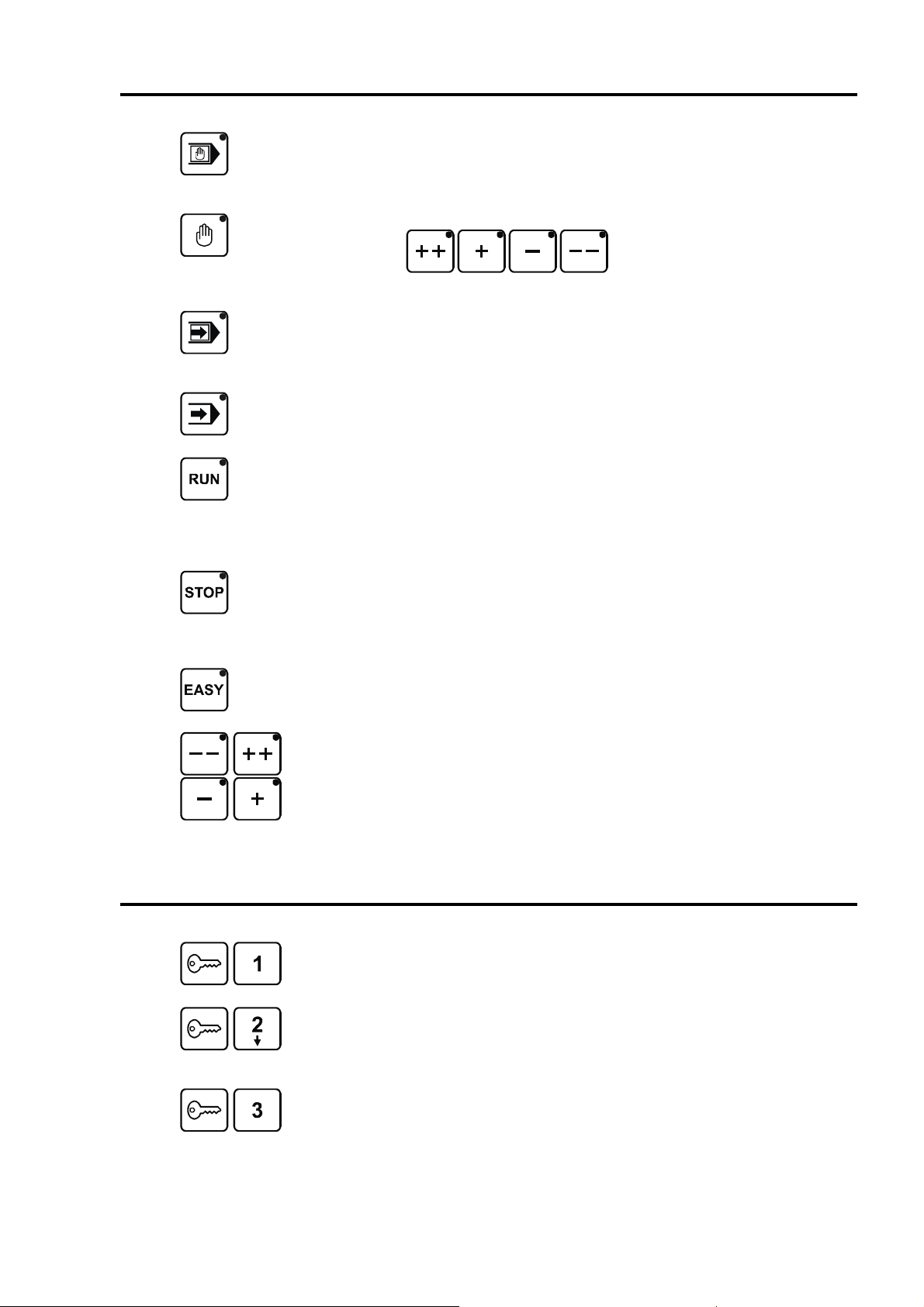
OPERATING MODES and MOVEMENT KEYS
Programming Mode Key :
Allows to introduce, store, modify, delete and search data for program, punch and
die.
Allows to modify data for machine parameters.
Manual Operating Mode Key :
Using the keys, allows to movement for selected
axis and crowning.
Semi Automatic Operating Mode Key :
Allows a machine cycle with the current step values without automatic step
change.
This mode is used for adjustment when realizing the first program.
Full Automatic Operation Mode Key :
Steps change automatically after each bend.
Program starts to operate from current step.
Run Key :
- Starts the axis and other control functions on semi or full automatic operation
mode.
- Calibration page is displayed after power on. Starts the axis calibration
(indexation) on this page.
During movement the led makes blink.
FUNCTION KEYS
Stop Key :
- Stops the axis and other control functions on semi or full automatic operation
mode.
- Stops the axis calibration. If pressing the key again while led is lighting on, exit
from calibration.
Easy Working Key :
Allows to make a single bend without losing the current program information.
Manual Movement Keys
Manual movement keys of the selected axis and crowning.
Function-1 Key
Allowable operations are; Program searching, step displaying, value changing and
operating modes.
Function-2 Key
Protecting password depending on selection. Allows to all F1 operation. Also;
memory operations of the program, punch and die (creation, modification, deleting
and saving). Also re-set of the actual values.
Function-3 Key
Protecting password depending on selection. Allowable operations are; Machine
parameters changing.
PAGE 9
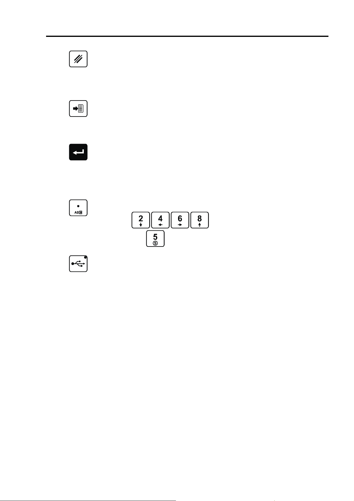
COMMAND KEYS
Delete Key :
Allows to following operations depends on cursor position;
- Delete a program from memory when the cursor is placed on the P field.
- Delete a current step from screen when the cursor is placed on the N field.
- On the TOOL page, delete a punch and die from memory when the cursor is
placed on the PUNCH(p) or DIE(d) fields.
- Delete a value from screen when the cursor is placed on programing field.
Search Key :
Allows to following operations depends on cursor position;
- Search for program on memory when the cursor is placed on the P field.
- On the TOOL page, search for punch and die on memory when the cursor is
placed on the PUNCH(p) or DIE(d) fields.
- On the CRITERION SEARCH page, search for program by criteria.
Store / Copy Key :
Allows to following operations depends on cursor position;
- Store the program in the memory when the cursor is placed on the P field.
- Copy new step consecutive includes current step data when the cursor is
placed on the N field.
- On the TOOL page, store punch and die in the memory when the cursor is
placed on the PUNCH(p) or DIE(d) fields.
- Approve the entered value when the cursor is placed on programing field.
Point / Code Key :
Character table displays when the cursor is placed on the CODE field.
keys are used to move cursor on the character
table,
USB Key :
Used to access to USB memory page. Also used to start to update process.
key is used to select character from table.
PAGE 10
CURSOR KEYS
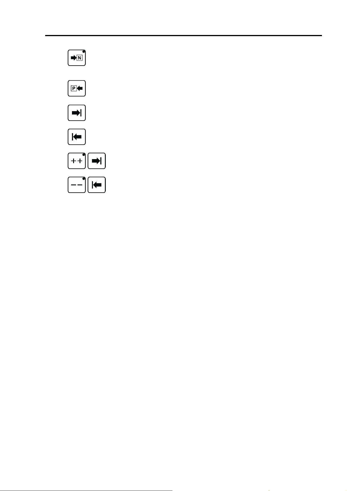
Next Step / Next Page Key :
Allows to pass next step on programming pages, next page on parameters pages
and next result page on listing pages.
The led indicates whether page is the last of the relevant pages.
Previous Step / Previous Page Key :
Allows to pass previous step on programming pages, previous page on
parameters pages and previous result page on listing pages.
Cursor Forward Key :
Cursor moves next accessible field.
Cursor Reverse Key :
Cursor moves previous accessible field.
With this key combination, cursor is send to last programmable field of the current
page.
With this key combination, cursor is send to first programmable field of the current
page.
PAGE 11
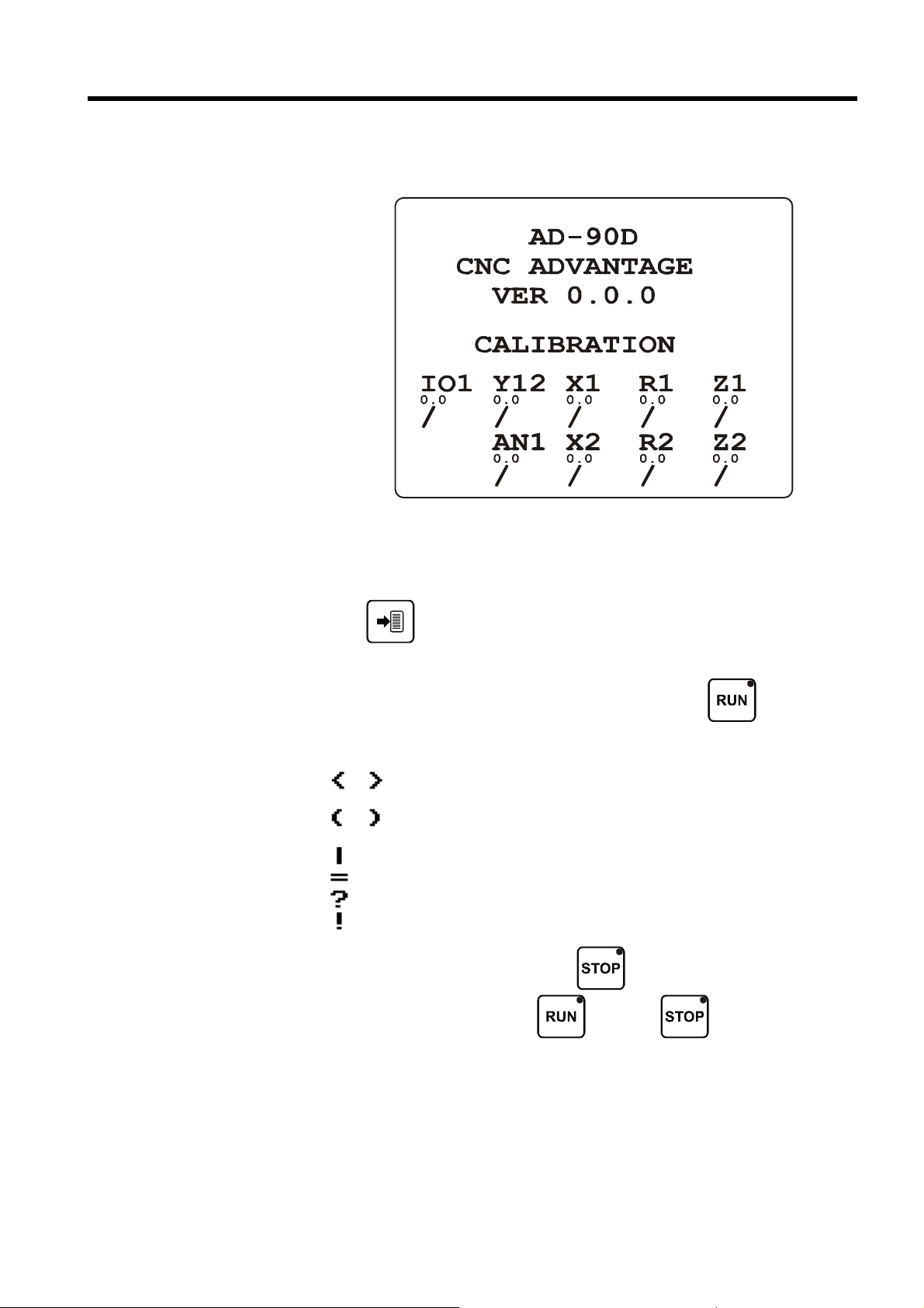
CALIBRATION
Calibration page is displayed first when the power on.
Checking the version is done before page is displayed. Version of the LCD panel is
displayed like VER 0.0.0. Version of the each module is displayed under the module
name like 0.0. If there is no any version problem, / symbol is displayed. If there is a
problem, nothing is displayed.
If the key is pressed, the panel will check the version again. Do not allow
any communication with the modules except checking the version.
The led lights on and calibration (indexation) starts when the
The led makes blink during calibration. Status of each axis is displayed with symbols
which explanations are give as follows.
or Movement is carrying on at the calibration speed and toward limit
switch on the defined direction.
or Limit is founded. Movement is carrying on for the index pulse at the 1/4
of the calibration speed and reverse direction.
Limit or index is founded, waiting to movement stop.
Calibration is completed successfully.
Axis is not moving.
Driver error.
Calibration can be stopped by pressing
can be started again by pressing
the key is pressed againg, turned to the normal working.
If the calibration is completed successfully for all axes, automatically turned to the
normal working.
key while operation is carrying on,
key. While
key is pressed.
key led is lighting, if
If the number of the last using program is available on the memory, the
PROGRAMING page is displayed. If not, PROGRAM LIST page is displayed.
PAGE 12
PROGRAMMING PAGES
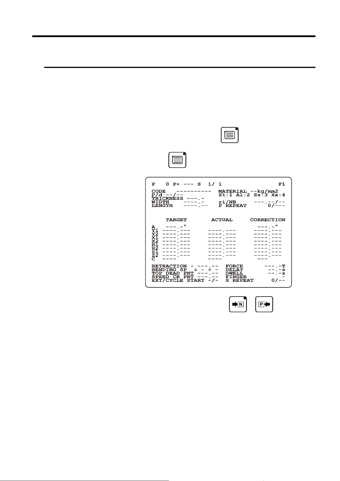
RECIPE PAGE
This page displays all the bending informations for the current step. That is the target
position of the axis, the pressure, the gauge retraction, the crowning and the dwell
time etc.
Because of that, an operator can directly program in this page, without passing other
pages.
To reach the programming page, press the
The first pressing to
key, displays the page in small characters.
key.
To change from one step to another, press the or key.
PAGE 13
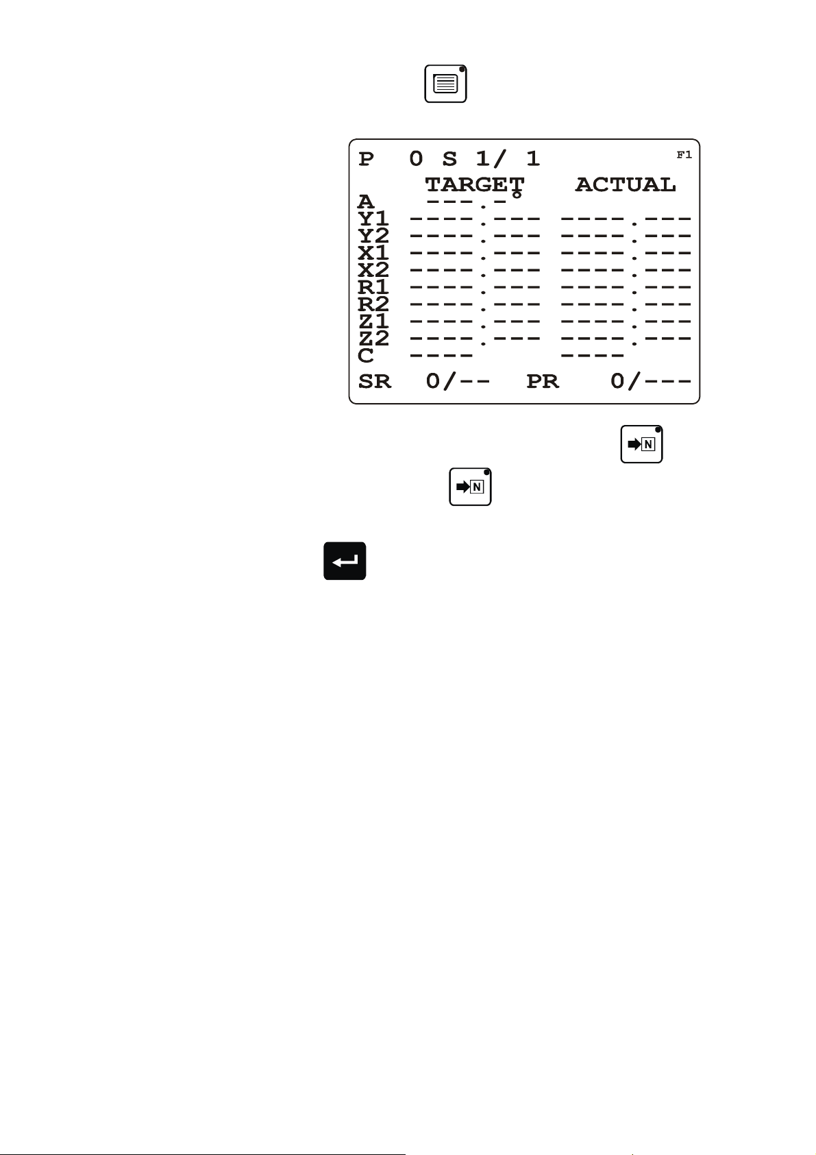
The second pressing to
repetition, step number and repetition, target and actual values in large characters.
When the last step of the program is reached, the led of the key lights up. At
key, displays the page program number and
this time, when pressing the
blank. A message ADDED is displayed.
If the
which contains same data with the current step is copied and COPIED message is
displayed.
key is pressed while the cursor is placed on the step field, a new step
key during 1second, a new step is created as a
PAGE 14

EXPLANATION OF THE RECIPE PAGE FIELDS
P
P+
S
CODE
MATERIAL
p / d
THICKNESS
WIDTH
ri / NB
LENGTH
P TEKRAR
TARGET
ACTUAL
CORRECTION
Number of the valid program in the working memory.
Number of the next program which will be executed automatically.
If this field is left empty, when the last step of the program is executed, the program
will return to the first step of the current program.
Number of current step and number of total step.
Consist characters from code table. Define as a supplementary information with the
program number in order to facilitate program searching.
Material selection for tensile strength.
Punch and die of the current step.
Material thickness.
Material width for the current step.
Internal bending radius and number of bend
Profile (face) length defined by the user.
Number of program cycle repetitions. First field displays number of the program
which is made, second field displays number of repetition.
Displays either the values calculated by the system or the values programmed by the
operator.
Displays the real positions.
Corrections defined for each step.
.
RETRACTION
FORCE
Displays if X axis is enabled. If the field leave undefined, retraction is not make and
bending is carried on continuously.
If the first field leave undefined or defined as 0, the BEAM stops at PP and waits until
the retraction is made. Then carry out the bend.
If the first field defined as 1, the BEAM stops at PP. Then continues bend
immediately, at the same time as the retraction is carring out.
Bending force is calculated automatically. Also operator can changed.
BENDING SP BEAM bending speed. If programmed at 0 the speed is 1mm/s, at 9 the
speed is 10mm/s.
BENDING SP BEAM rising speed from BDP to PP. If programmed at 0 rising slow, at 9
rising fast.
DELAY
TOP DEAD PNT
DWELL
SPEED CH PNT
FINGER
EXT/CYCLE START
S REPEAT
At the end of upwards movement of the beam, time delay for the pass next step
(cycle) operation.
Top dead point (TDP). Distance from the BEAM rising finished.
Wait time of the beam at the BDP.
Speed change point (SCP). Distance from the BEAM speed changing from HS to LS.
NOT IN USE
External start (0 : YES, 1 : NO) and new cycle starting point (0 : BDP, 1 : PP, 2 :
TDP) selection.
Number of current step repetitions. First field displays number of current step
repetition which is made, second field displays number of repetition. If the second
field is not defined, step is made 1 time. If defined as 0 pass on the next step.
PAGE 15
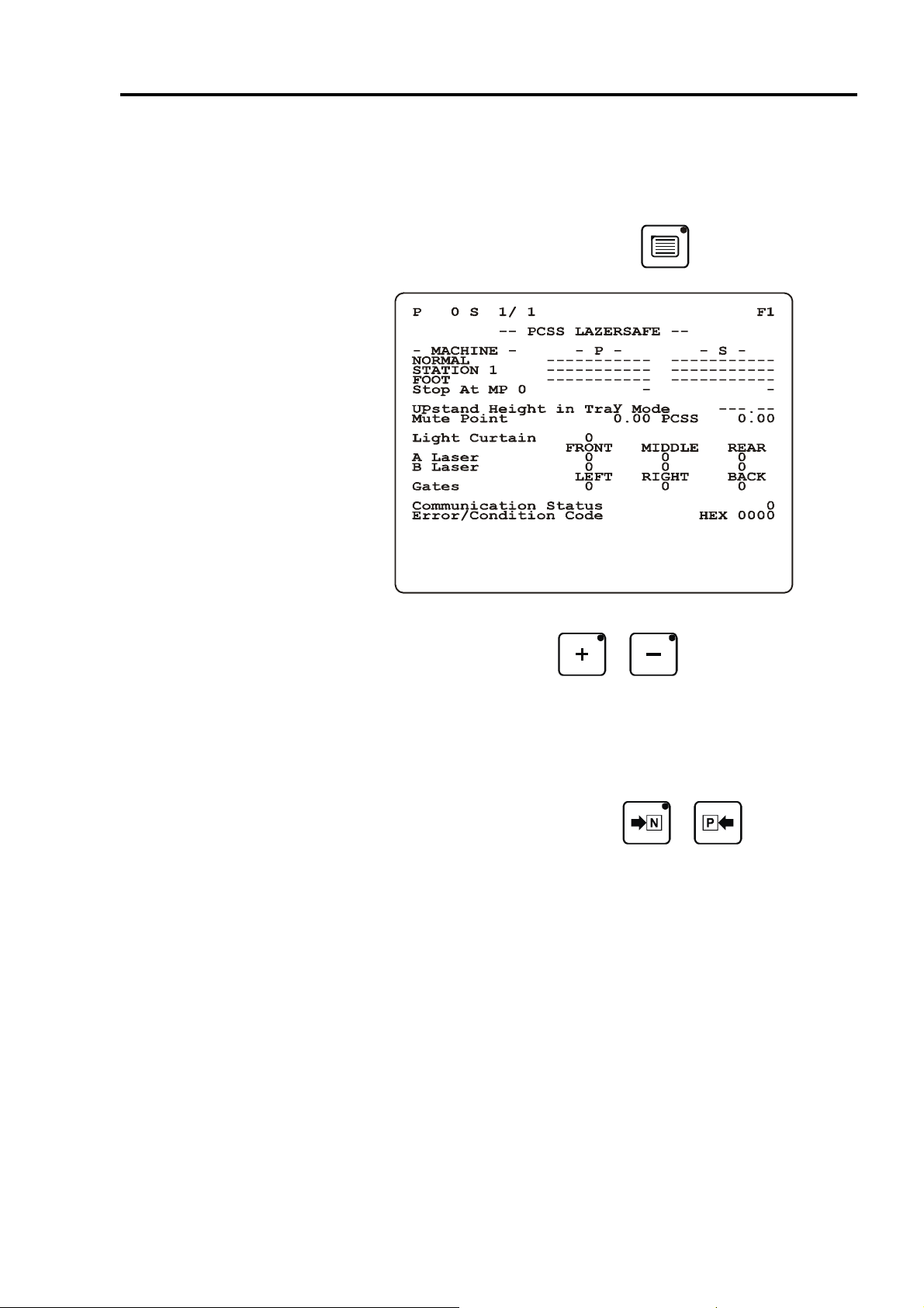
PCSS LAZERSAFE PAGE
This page is displayed if PCSS LAZERSAFE parameter (P810) is enabled.
This page indicates, PCSS information belonging to current step with a sensor
status, communication status and error / status code sent by PCSS.
To reach the PCSS LAZERSAFE page, press the key again.
Working Mode, Operator Selection and Station Type value belonging to – P – and
– S – fields can be selected with the
choosing from a created list according to PCSS parameter (P811, P812, P813 and
P814) values.
Fristly, values in the – S – filed is used for PCSS kontrol. However, equivalent in the
– P – filed is used for the left undefined values. These values have been left in the
still undefined in this case equivalent in the – MACHINE – filed is used.
To change from one step to another, press the
or keys. Selection is done by
or key.
PAGE 16

EXPLANATION OF THE PCSS LAZERSAFE PAGE FIELDS
P
S
– MACHINE –
– P –
– S –
Upstand Height
in Tray Mode
Mute Point
Light Curtain
A Laser
B Laser
Gates
Communication Status
Number of the valid program in the working memory.
Number of current step and number of total step.
Display parameter (P815 – Working Mode, Operator Selection, Station Type and
Stop At Mute Point) values for the PCSS.
Display entered program (Working Mode, Operator Selection, Station Type and
Stop At Mute Point) values for the PCSS.
Display entered step (Working Mode, Operator Selection, Station Type and Stop
At Mute Point) values for the PCSS.
Side height for the box bending.
First displayed value is calculated by CNC. Second displayed value is send by
PCSS. PCSS is used to great one.
Display the status of Ligh Curtain on PCSS if parameter (P812) is defined.
Display the status of Laser A on PCSS if parameter (P811) value is equal to 1 or 2.
Display the status of Laser B on PCSS if parameter (P811) value is equal to 2.
Display the status of gates on PCSS.
Display the status of communication between CNC and PCSS.
0 Communication test.
1 Communication error.
2 No reply from PCSS.
3 Checksum error.
4 Answer of PCSS is unknown.
5 Error on PowerUp or Jop parameters.
6 PCSS has sent Error/Condition message.
7 Waiting reply from PCSS during test.
Error/Condition Code
Display the Error/Condition Code send by PCSS as hexedecimal (0x0000).
PAGE 17
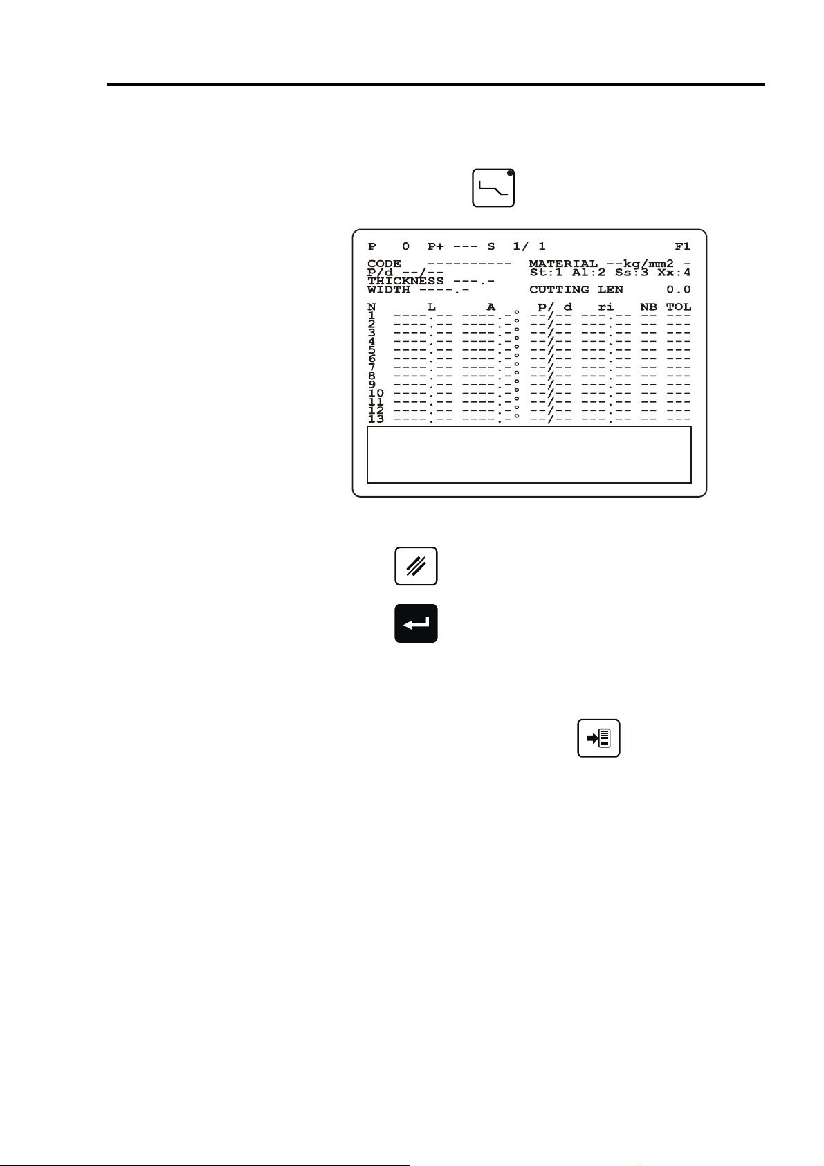
PROFLE PAGE
On this page, programming is done by entering the face length and bending angle
values of the desired product.
Profile page is displayed on the
To perform profile, face length and bending angle values are entered.
While the cursor placed over any one of the number under N field;
- By pressing the
deleted.
key, relevant row containing the profile information can be
key first pressed.
- By pressing the key, new row containing the relevant profile information
can be copied.
After both operation, following profile rows are moved automatically.
After entering the last face length, cutting (unfolded) length and internal bending
radius for each step are calculated by pressing the
Also, image belonging to entered profile is diplayed on the window bottom side of the
LCD screen. (Resolution is 240x48pixels)
key.
PAGE 18

EXPLANATION OF THE PROFILE PAGE FIELDS
P
P+
S
CODE
MATERIAL
p / d
THICKNESS
WIDTH
CUTTING LEN
N
L
A
p / d
Number of the valid program in the working memory.
Number of the next program which will be executed automatically.
If this field is left empty, when the last step of the program is executed, the program
will return to the first step of the current program.
Number of current step and number of total step.
Consist characters from code table. Define as a supplementary information with the
program number in order to facilitate program searching.
Material selection for tensile strength. Second filed defines the coefficient will be
used cutting (unfolded) length calculation.
Punch and die of the current program.
Material thickness.
Material width for the current program.
Cutting (unfolded) length of the product calculated by the system according to DIN
6935 standard.
Displays the face number of the entered profile. It may be max 13. For more profile,
P+ can be used.
Defines the distance between two bends or the distance between the edge of the
sheet and the first bend.
Bending angle.
For each bend, different punch or die can be used.
ri
NB
TOL
Displays the internal bending radius. When the key is pressed, ri is
calculated taking into account the bending angle, the material and the tools.
Number of bends defined by the user to make internal bending radius.
Display the calculated tolerance according to user defined internal bending radius
and number of bend.
PAGE 19
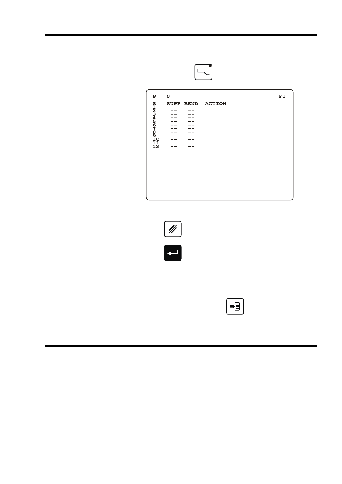
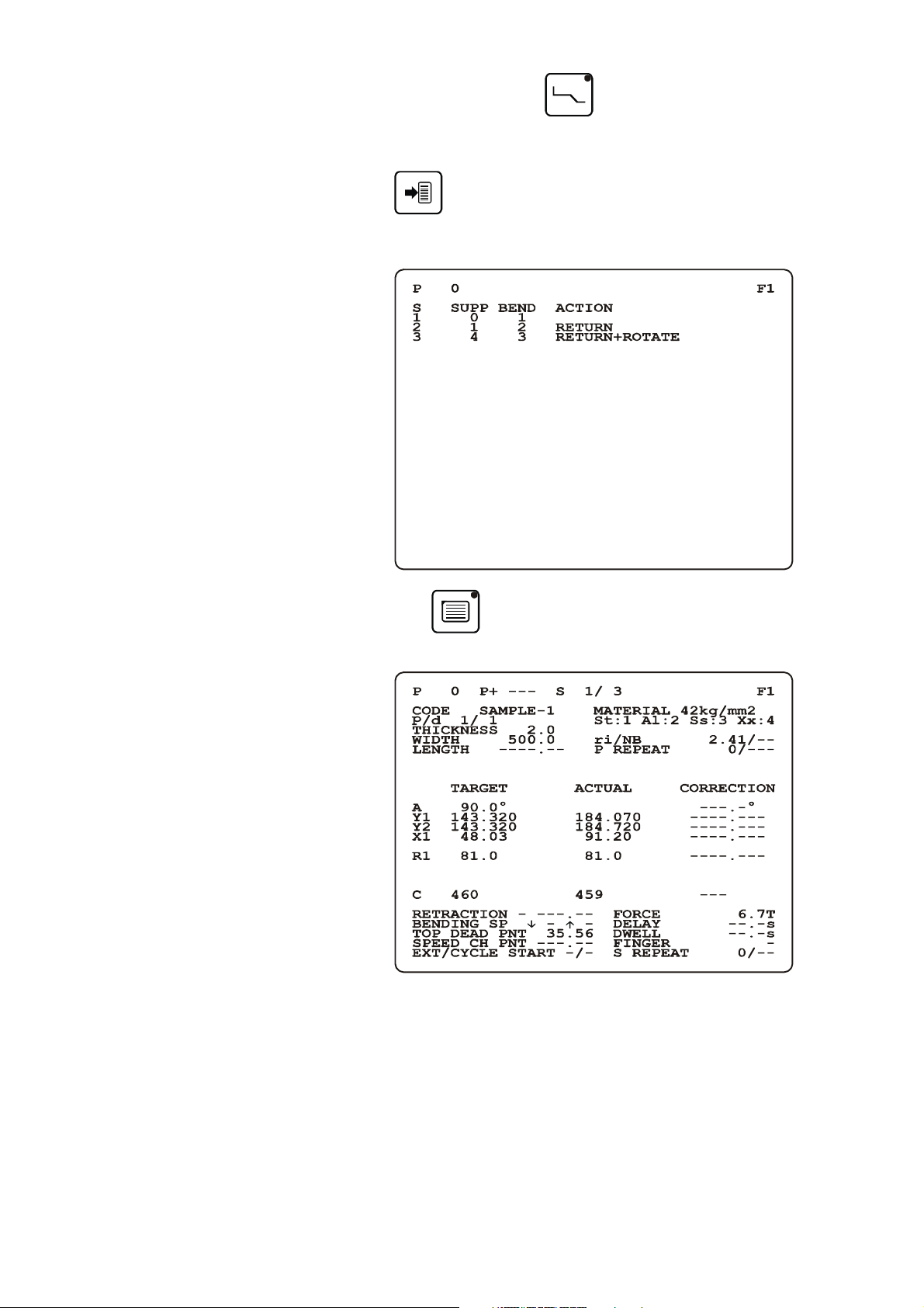
ORDER PAGE
On this page, bending order belonging to profile is entered.
Order page is displayed on the key second pressed.
To perform order, support and bending numbers are entered.
While the cursor placed over any one of the number under S field;
- By pressing the
deleted.
- By pressing the key, new row containing the order profile information can
be copied.
After both operation, following order rows are moved automatically.
After entering the last support and bending number, whole program (axis set,
retraction, TDP etc.) values are calculated and displays the sheet metal actions to be
made before each sequence by pressing the
key, relevant row containing the order information can be
EXPLANATION OF THE ORDER PAGE FIELDS
P
S
Number of the valid program in the working memory.
Displays the step (bending) number of the entered profile. It may be max 12.
key.
SUPP
BEND
ACTION
Support number can be enter between 0 and FaceNumber.
Bending number can be enter between 1 and FaceNumber – 1.
The sheet metal actions to be made before each sequence
- Return
- Rotate
- Return + Rotate
.
PAGE 20
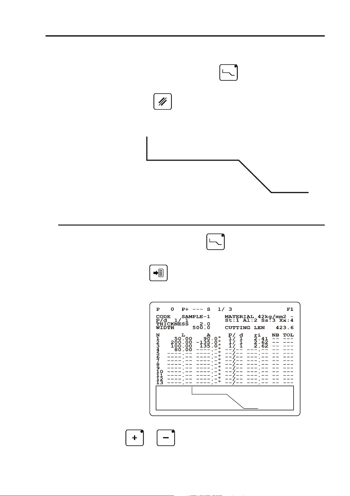
SAMPLE – 1
-135°
+135°
In order to program a new product, the work memory must be cleared.
ENTER A PROFLE
- Open the profile page by pressing the
- Move the cursor over S field and enter the value 99.
- Press the
The profile in our sample is defined as follows :
THICKNESS = 2.0mm, MATERIAL = 42kg/mm2, WIDTH = 500.0mm.
0
key.
key.
50
1
+90°
200
2
100
Open profile page by pressing the
sample profile above.
3
key.. Fill in the fields according to the
80
4
Press the
for each step are calculated. Also, image belonging to entered profile is diplayed on
the window bottom side of the LCD screen. (Resolution is 240x48pixels)
In order to obtain better resolution, profile image can be rotated ±45° by pressing the
and keys.
key. Thus, cutting (unfolded) length and internal bending radius
PAGE 21
DEFINITION OF THE BENDING ORDER
234
4
0
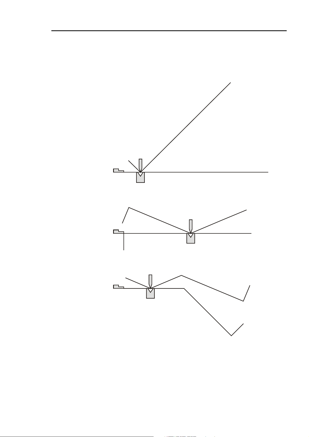
The following images display the desired bending order.
For each step, the image displays the sheet metal with its bend before and after
bending.
Step S1 : Support = 0 ve Bend = 1
0 1
Step S2 : Support = 1 ve Bend = 2
1
0
Step S3 : Support = 4 ve Bend = 3
4
3
2
2
3
1
PAGE 22
Open profile page by pressing the
Enter the bending order displayed above images in the SUPP and BEND fields.
key again.
Press the
are calculated and displays the sheet metal actions to be made before each
sequence.
By pressing the
each steps can be displayed.
key. Thus, whole program (axis set, retraction, TDP etc.) values
key, recipe page can be opened and calculation results for
You can see the SAVING PROGRAM section in order to save created recipe (with
the profile and ordering information) above.
PAGE 23
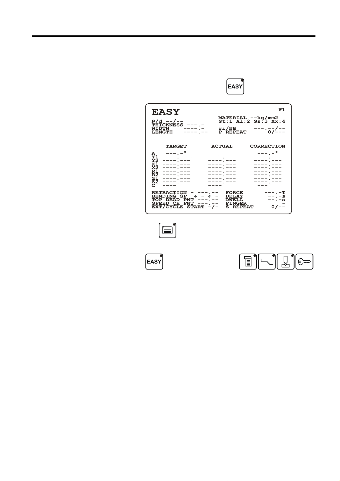
EASY WORKING PAGE
With the EASY working page, allows to programming a single bend without loss or
modification of the program in hand.
To access the EASY working page, press the
By pressing the key while in EASY page, other recipe page or PCSS page (if
P810 is active) can be displayed without exit the EASY mode.
key.
When the
key pressed, displaying new page together with exit the EASY mode.
key pressed again or one of the
PAGE 24
 Loading...