

Page 1

Teile-Nr./ Part-No.:
0791 867701
Printed in Federal Republic of Germany
Ausgabe/Edition:
05. 2006
Blatt: von
Sheet: 1 from 8
1. Allgemeine Information
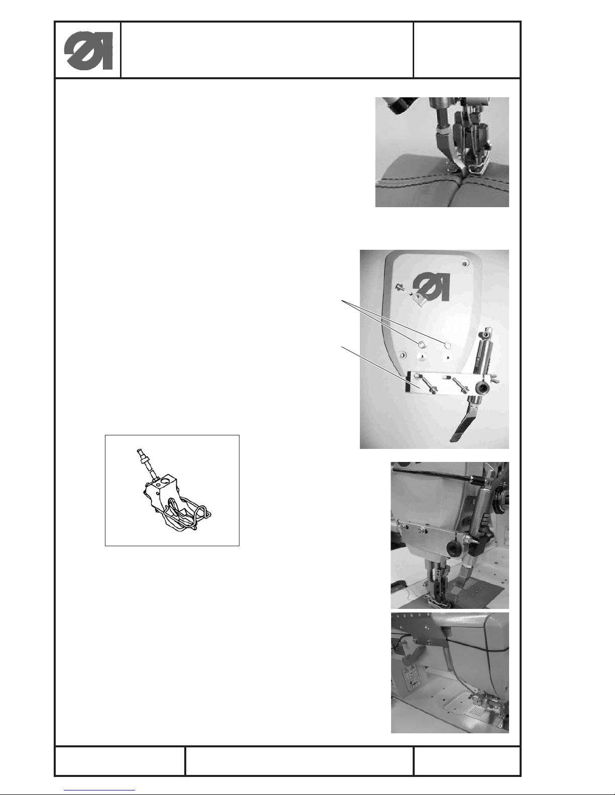
Die Nahtmittenführung dient als Führungshilfe beim Absteppen.
Die Nahtmittenführung soll die Mitte zweier gleichabständiger Nähnähte führen, damit der Abstand
zur linken und rechten Nadel gleich gross ist.
Anbaubar an alle Zweinadel-Spezialnähmaschinen der Klasse 867 mit der Näheinrichtung E24.
2. Mechanische Nahtmittenführung
2.1 Inhalt des Teilesatzes
Der komplette Bausatz zum Anbauen der mechanischen Nahtmittenführung mit der Bestell-Nr.:
N800 005655 besteht aus folgenden Komponenten:
1 x 0667 245004 Anschlag V
2 x 9202 002077 Zyl. Schraube (M4x10)
2 x 9202 002877 Zyl. Schraube (M6x10)
2 x 9330 000087 Scheibe (A4,3)
1 x N800 075013 Lineal, K
1 x N800 080003 Halter
2.2 Nahtmittenführung montieren
–
Den vormontierte Nahtmittenführung 1 mit den Schrauben 2
von hinten an den Nähkopf schrauben.
–
Nahtmittenführung 1 waagerecht zur Tischplatte ausrichten und darauf achten,
dass der Abstand zur linken und rechten Nadel gleich gross ist.
Der Abstand zwischen Führung 3 und Stichplatte soll
ca. 1mm betragen.
Klasse 867 Anbauanleitung Nahtmittenführungen
N800 005655 (mechanisch) N800 005650 (pneumatisch)
Class 867 Instructions for fitting seam center guide
N800 005655 (mechanical) N800 005650 (pneumatically)
231
1mm
Page 2
3. Pneumatische Nahtmittenführung
3.1 Inhalt des Teilesatzes
Der komplette Bausatz zum Anbauen der mechanischen
Nahtmittenführung mit der Bestell-Nr.: N800 005650
besteht aus folgenden Komponenten:
1 x 0667 105164 Kopfdeckel
1 x 0667 595050 Halter
2 x 1001 009243 Scheibe
2 x 9202 002107 Zyl. Schraube (M4x20)
1 x 9204 211997 Flachkopfschr. (M5x16)
1 x 9205 102778 Gew. Stift (M8x8)
1 x 9217 000157 Flügelschraube (M4x16)
1 x 9231 110127 6kt. Mutter (M6)
3 x 9330 000087 Scheibe (A4,3)
1 x 9700 100040 Zylinder, einf.
1 x 9710 920013 Drosselventil
1 x N800 005614 Anschlag
1 x N800 005615 Druckstück
1 x 9840 120026 Bef. Schelle
1 x 9204 201667 Linsenschraube (M4x10)
1 x 0867 590064 Pneum. Anschluss kpl.
- 9870 867005 Leitung k, für Magnetventil
- 9815 301082 Tastenknopf
- 0797 000317 Magnetventil
(Achtung: Magnetventil stromlos geöffnet.)
Variante: Integrierte Nahtmittenführung
im Drückerfuss für Klasse 867
mit E24/... / ... mm Stichlänge.
3.2 Nahtmittenführung am Nähkopf montieren
–
Kopfdeckel demontieren.
–
Neuen Kopfdeckel 0667 105164 montieren.
–
Vormontierte Nahtmittenführung mit Halter 2 an den
Kopfdeckel anschrauben, dabei die Scheiben 1
in die Aussenkungen des Kopfdeckels und zwischen
den Halter 2 legen.
–
Den Pneumatikschlauch mit der Befestigungsschelle am
Kopfdeckel anschrauben und nach hinten verlegen (sh. Abb.).
Mit Kabelbinder am vorhandenen Kabelbaum befestigen
und bis zur Wartungseinheit verlegen. Dabei ist darauf achten,
dass der Schlauch nicht geknickt wird.
Klasse 867 Anbauanleitung Nahtmittenführungen
N800 005655 (mechanisch) N800 005650 (pneumatisch)
Class 867 Instructions for fitting seam center guide
N800 005655 (mechanical) N800 005650 (pneumatically)
Teile-Nr./ Part-No.:
0791 867701
Printed in Federal Republic of Germany
Ausgabe/Edition:
05. 2006
Blatt: von
Sheet: 2 from 8
1
2
Page 3
Teile-Nr./ Part-No.:
0791 867701
Printed in Federal Republic of Germany
Ausgabe/Edition:
05. 2006
Blatt: von
Sheet: 3 from 8
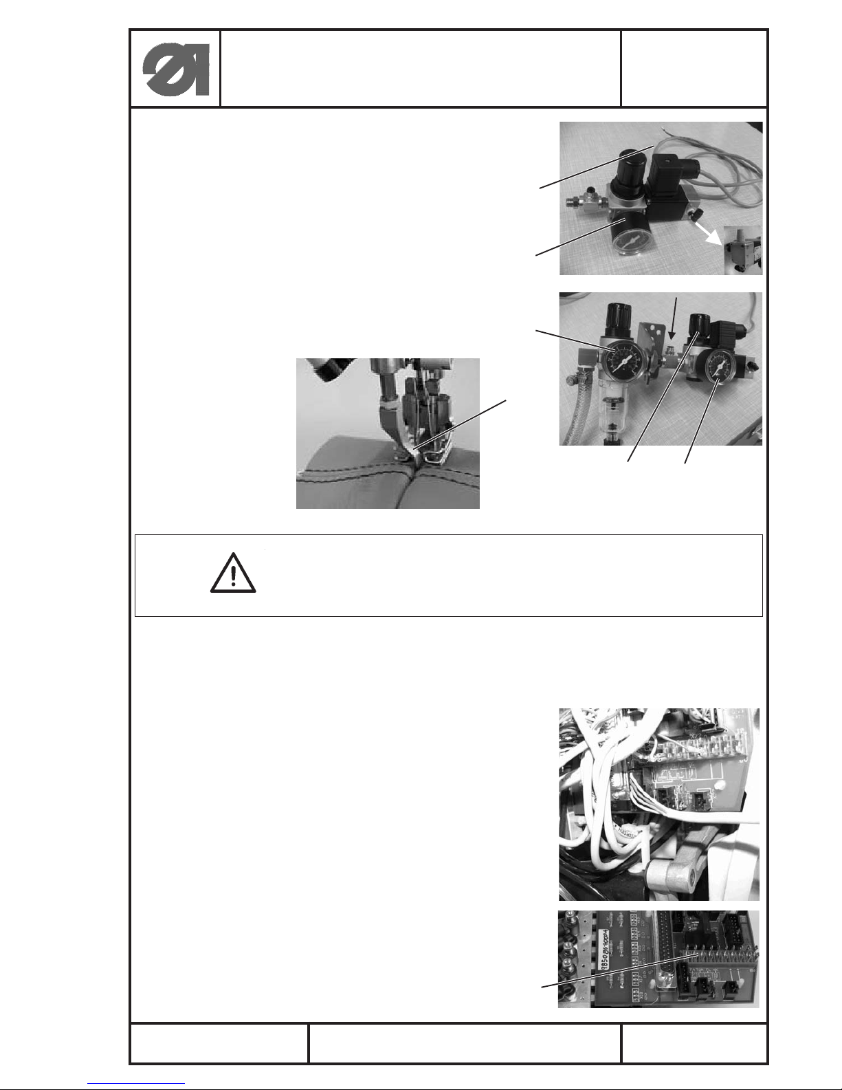
3.3 Druckluftwartungseinheit komplettieren
–
Den vormontierten pneumatischen Anschluss 1 mit der
vorhandenen Wartungseinheit 2 (an der Gestellstrebe)
verbinden und den Pneumatikschlauch anschliessen.
(Siehe Aufstellanleitung Punkt 7 Pneum. Anschluss).
3.4 Nahtmittenführung ausrichten
–
Die Führung 3 soll mittig und so dicht wie möglich
zum Nähfuss stehen, damit der Abstand zur linken
und rechten Nadel gleich gross ist.
Der Abstand zwischen Führung 3 und Stichplatte soll
ca. 1mm betragen.
Achtung!
Der Druck für die Nahtmittenführung darf maximal 3 bar betragen.
Abzulesen am Manometer 5 und einzustellen am Drehgriff 4.
3.5 Elektrischen Anschluß herstellen
Achtung !
Alle Arbeiten an der elektrischen Ausrüstung der Spezialnähmaschine dürfen nur von Elektrofachkräften oder entsprechend
unterwiesenen Personen durchgeführt werden.
Der Netzstecker muss heraugezogen sein!
Die dem Nähantrieb beiliegende Betriebsanleitung des Herstellers
ist unbedingt zu beachten!
–
Das Kabel 6 vom Magnetventil (vormontierter pneumatischer
Anschluss) nach oben in den Verteiler legen und an der
Ventilleiterplatte an Steckleiste 7, X22, PIN3 (FF3 OUT)
und PIN 1, 7 oder 8 (+24V) anschliessen.
Klasse 867 Anbauanleitung Nahtmittenführungen
N800 005655 (mechanisch) N800 005650 (pneumatisch)
Class 867 Instructions for fitting seam center guide
N800 005655 (mechanical) N800 005650 (pneumatically)
6
1
2
3
45
7
Page 4

4. Arbeitsweise und Parametereinstellung der Nahtmittenführung
Im ausgeschaltetem Zustand der Maschine ist die Nahtmittenführung unten (= Magnetventil
elektrisch aus). Unmittelbar nach dem Einschalten der Maschine befindet sich die Nahtmittenführung
immer oben (= Magnetventil elektrisch ein).
Mit dem Taster 1 (siehe Betriebsanleitung) im 6er-Tastensatz an der Maschine kann die
Nahtmittenführung jederzeit ein- und ausgeschaltet werden.
Die Taste 1 (weiss) muss im 6er-Tastensatz durch die
Tastenkappe 2 mit dem Symbol “Nahtmittenführung” ersetzt
werden.
Erforderliche Parametereinstellungen:
Nähantrieb/Steuerung
DC 1550/DA 321G DC 1600/DA 82GA
F-275 auf Wert ”5" F-149 auf Wert “3"
Mögliche Parametereinstellungen für die Nahtmittenführung:
Parameter Wert Funktion Nahtmittenführung...
DA321G DA82GA
F-278 F-186 0 ... nur ein- und aus durch Taster 1 im
F-278 F-186 >0 ... automatisch ein nach Stichzählung
F-260 F-260 0-OFF ... absenken nach Nähfusslueftung mit Stichzählung aus.
1-ON ... absenken nach Nähfusslueftung nach eingestellter Stichzahl
DA82GA: PAR F-186
DA321G: PAR F-278
F-261 F-261 0 ... bei Riegel und Nähfußlüftung immer ein, wenn sie eingeschaltet ist
F-261 1 ... aus nur während Riegel und Nähfußlüftung, wenn sie vorher
eingeschaltet ist
F-261 2 ... aus nur während Nähfußlüftung, wenn sie vorher eingeschaltet ist
F-261 3 ... aus nur während dem Riegel, wenn sie vorher eingeschaltet ist
F-262 F-262 0 ... bei Hubverstellung (HP) durch Knietaster immer ein, wenn sie
eingeschaltet ist
F-262 1 ... aus während Hubverstellung (HP) durch Knietaster, wenn sie
vorher eingeschaltet ist.
Ist die Nahtmittenführung aus (oben), bleibt der Zustand erhalten, unabhängig davon wie die
Parameter F-261 und F-262 eingestellt sind und welche Funktion wirksam ist.
Klasse 867 Anbauanleitung Nahtmittenführungen
N800 005655 (mechanisch) N800 005650 (pneumatisch)
Class 867 Instructions for fitting seam center guide
N800 005655 (mechanical) N800 005650 (pneumatically)
Teile-Nr./ Part-No.:
0791 867701
Printed in Federal Republic of Germany
Ausgabe/Edition:
05. 2006
Blatt: von
Sheet: 4 from 8
1
2
Page 5

Teile-Nr./ Part-No.:
0791 867701
Printed in Federal Republic of Germany
Ausgabe/Edition:
05. 2006
Blatt: von
Sheet: 5 from 8
1. General information
The seam center guide serves as guiding aid when topstitching.
It is used for guiding the center of two seams with equal distance so that the distance to the left and
to the right needle is equal.
Can be fitted to all twin needle special sewing machines of class 867 with sewing equipment E24.
2. Mechanical seam center guide
2.1 Contents of the set of parts
The complete mounting kit for fitting the mechanical seam center guide with the order no.
N800 005655 consists of the following components:
1 x 0667 245004 Stop guide V
2 x 9202 002077 Cylinder head screw (M4x10)
2 x 9202 002877 Cylinder head screw (M6x10)
2 x 9330 000087 Disc (A4,3)
1 x N800 075013 Ruler, K
1 x N800 080003 Holder
2.2 Fitting the seam center guide
–
Screw the pre-assembled seam center guide 1 on the
sewing head from behind with the screws 2.
–
Align the seam center guide 1 horizontally to the table top and take care,
that the distance to the left and the r ight needle is equal.
The distance between guide 3 and the throat plate should
amount to approx. 1 mm.
Klasse 867 Anbauanleitung Nahtmittenführungen
N800 005655 (mechanisch) N800 005650 (pneumatisch)
Class 867 Instructions for fitting seam center guide
N800 005655 (mechanical) N800 005650 (pneumatically)
231
1mm
Page 6

3. Pneumatical seam center guide
3.1 Contents of the set of parts
The complete mounting kit for fitting the pneumatical
seam center guide with the order no. N800 005650
consists of the following components:
1 x 0667 105164 Head cover
1 x 0667 595050 Holder
2 x 1001 009243 Disc
2 x 9202 002107 Cylinder head screw (M4x20)
1 x 9204 211997 Flat headed screw (M5x16)
1 x 9205 102778 Threaded pin (M8x8)
1 x 9217 000157 Wing screw (M4x16)
1 x 9231 110127 Hexagonal nut (M6)
3 x 9330 000087 Disc (A4,3)
1 x 9700 100040 Cylinder, single
1 x 9710 920013 Throttle valve
1 x N800 005614 Stop guide
1 x N800 005615 Thrust piece
1 x 9840 120026 Fastening clamp
1 x 9204 201667 Oval head screw (M4x10)
1 x 0867 590064 Pneum. connection cpl.
- 9870 867005 Cable k, for solenoid valve
- 9815 301082 Push button
- 0797 000317 Solenoid valve
(Attention: Solenoid valve non-energised open)
Variant: Integrated seam center guide
in the presser foot for class 867
with E24/... / ... mm stitch length.
3.2 Mounting the seam center guide on the sewing head
–
Remove the head cover.
–
Mount new head cover 0667 105164.
–
Screw pre-assembled seam center guide with holder 2 on the
head cover and place the discs 1
into the recesses of the head cover and between the holder 2.
–
screw the pneumatic hose with the fastening clamp on the
head cover and guide it to the back (see ill.).
Fasten it at the cable harness with cable ties and guide it to the
maintenance unit. Take care that the hose is not bent.
Klasse 867 Anbauanleitung Nahtmittenführungen
N800 005655 (mechanisch) N800 005650 (pneumatisch)
Class 867 Instructions for fitting seam center guide
N800 005655 (mechanical) N800 005650 (pneumatically)
Teile-Nr./ Part-No.:
0791 867701
Printed in Federal Republic of Germany
Ausgabe/Edition:
05. 2006
Blatt: von
Sheet: 6 from 8
1
2
Page 7

Teile-Nr./ Part-No.:
0791 867701
Printed in Federal Republic of Germany
Ausgabe/Edition:
05. 2006
Blatt: von
Sheet: 7 from 8
3.3 Completing the compressed air maintenance unit
–
Connect the pre-assembled pneumatic connection 1 and the
available maintenance unit 2 (on the strut of the stand)
and connect the pneumatic hose.
(see assembly instructions item 7 pneumatic connection).
3.4 Aligning the seam center guide
–
The guide 3 should be in central position and as close
as possible to the sewing foot so that the distance to
the left and the right needle is equal.
The distance between guide 3 and the throat plate
should amount to approx. 1 mm.
Attention!
The pressure for the seam center guide must not exceed 3 bar.
To be read off at the manometer 5 and to be set at the turning
handle 4.
3.5 Making the electrical connection
Attention !
All operations on the electrical equipment of the special
sewing machine must only be carried out by electricians or
correspondingly trained personnel.
The mains plug has to be pulled out!
The manufacturer ’s operating instructions enclosed to
the sewing drive have to be observed by all means!
–
Lay the cable 6 from the solenoid valve (pre-assembled
pneumatic connection) upwards in the distributor and
connect it to the cable connector 7, X22, PIN3 (FF3 OUT)
and PIN 1, 7 or 8 (+24V) at the printed circuit board.
Klasse 867 Anbauanleitung Nahtmittenführungen
N800 005655 (mechanisch) N800 005650 (pneumatisch)
Class 867 Instructions for fitting seam center guide
N800 005655 (mechanical) N800 005650 (pneumatically)
6
1
2
3
45
7
Page 8

4. Working method and parameter setting of the seam center guide
When the machine is switched off, the seam center guide is in position “down” (= solenoid valve
electrically off). As soon as the machine is switched on, the seam center guide is always in position
“up” (= solenoid valve electrically on).
With key 1 (see operating instructions) on the 6-key pad at the machine the seam center guide can
be switched on or off at any time.
Key 1 (white) of the 6-key pad has to be replaced by the
key cap 2 with the symbol “seam center guide”.
Required parameter settings:
Sewing drive/control
DC 1550/DA 321G DC 1600/DA 82GA
F-275 on value ”5" F-149 on value “3"
Possible parameter settings for the seam center guide:
Parameter Value Function seam center guide...
DA321G DA82GA
F-278 F-186 0 ... only on and off by key 1
F-278 F-186 >0 ... automatically on after stitch counting
F-260 F-260 0-OFF ... lowering after sewing foot lifting with stitch counting off.
1-ON ... lowering after sewing foot lifting after the set number of stitches
DA82GA: PAR F-186
DA321G: PAR F-278
F-261 F-261 0 ... when tacking and sewing foot lifting always on, if it is switched on
F-261 1 ... only off during tacking and sewing foot lifting, if it has been
switched on before
F-261 2 ... only off during sewing foot lifting, if it has been switched on before
F-261 3 ... only off during tacking, if it has been switched on before
F-262 F-262 0 ... during stroke adjustment (HP) by knee switch always on, if it
is switched on
F-262 1 ... off during stroke adjustment (HP) by knee switch, if it
has been switched on before.
If the seam center guide is off (position “up”), the status is maintained, irrespective of how the
parameters F-261 and F-262 are set and which function is active.
Klasse 867 Anbauanleitung Nahtmittenführungen
N800 005655 (mechanisch) N800 005650 (pneumatisch)
Class 867 Instructions for fitting seam center guide
N800 005655 (mechanical) N800 005650 (pneumatically)
Teile-Nr./ Part-No.:
0791 867701
Printed in Federal Republic of Germany
Ausgabe/Edition:
05. 2006
Blatt: von
Sheet: 8 from 8
1
2
 Loading...