

Page 1

667
Service Instructions
Page 2

IMPORTANT
READ CAREFULLY BEFORE USE
KEEP FOR FUTURE REFERENCE
All rights reserved.
Property of Dürkopp Adler AG and protected by copyright. Any reuse of these contents, including
extracts, is prohibited without the prior written approval of Dürkopp Adler AG.
Copyright © Dürkopp Adler AG 2016
Page 3

Table of Contents
1 About these service instructions..............................................3
1.1 Scope of the service instructions..................................................3
1.2 Representation conventions – symbols and characters............... 3
1.3 Other documents..........................................................................4
1.4 Liability..........................................................................................4
2 Safety...........................................................................................5
2.1 Basic safety instructions............................................................... 5
2.2 Signal words and symbols used in warnings................................6
3 Working basis............................................................................. 9
3.1 Order of the settings..................................................................... 9
3.2 Cable routing................................................................................9
3.3 Removing the covers..................................................................10
3.3.1 Tilting and erecting the machine head........................................10
3.3.2 Removing and placing the arm cover......................................... 11
3.3.3 Removing and placing the head cover.......................................12
3.3.4 Removing and placing the valve cover.......................................13
3.3.5 Removing and installing the throat plate ....................................14
3.3.6 Removing and installing the feed dog ........................................15
3.4 Flats on shafts ............................................................................16
3.5 Locking the sewing machine in place......................................... 16
3.6 Setting the handwheel into position............................................18
4 Positioning the arm shaft.........................................................19
5 Setting the handwheel scale ...................................................21
6 Positioning the toothed belt wheels....................................... 23
6.1 Setting the upper toothed belt wheel..........................................23
6.2 Setting the lower toothed belt wheel...........................................25
7 Setting the stitch length adjusting wheels............................. 27
7.1 Setting the upper stitch length adjusting wheel..........................28
7.2 Setting the lower stitch length adjusting wheel...........................30
7.3 Setting the stitch length limit.......................................................32
7.4 Setting the eccentric for the forward and backward stitches...... 33
8 Setting the feed dog................................................................. 35
8.1 Setting the feed dog position......................................................35
8.1.1 Moving the feed dog...................................................................36
8.1.2 Moving the feed dog carrier........................................................37
8.2 Setting the feed dog movement..................................................38
8.2.1 Setting the feed movement.........................................................38
8.2.2 Setting the feed dog height at top dead center...........................39
8.2.3 Setting the stroke movement......................................................40
9 Aligning the needle bar linkage...............................................43
9.1 Moving the needle bar linkage sideways....................................43
9.2 Aligning the needle bar linkage in the sewing direction..............45
10 Position of the hook and needle ............................................. 47
10.1 Setting the hook side clearance .................................................47
Service Instructions 667 - 00.0 - 04/2016 1
Page 4

Table of Contents
10.2 Setting the loop stroke position ..................................................49
10.3 Setting the needle bar height......................................................51
11 Sewing feet................................................................................53
11.1 Setting an even sewing foot stroke.............................................54
11.2 Setting the stroke movement for the feeding foot.......................55
11.3 Setting the sewing foot pressure................................................57
11.4 Setting the sewing foot lifting height........................................... 58
12 Setting the needle thread tension...........................................59
12.1 Setting the needle thread regulator............................................59
12.2 Setting the thread tensioning spring...........................................60
13 Winder .......................................................................................61
13.1 Setting the winder.......................................................................61
13.2 Setting the hook thread guide.....................................................64
14 Thread cutter............................................................................. 65
14.1 Setting the control cam position .................................................65
14.2 Setting the armature of the thread cutter magnet.......................66
14.3 Setting the position of the thread-pulling knife............................67
14.4 Setting the cutting pressure........................................................68
15 Setting the potentiometer........................................................ 71
16 Maintenance..............................................................................73
16.1 Cleaning .....................................................................................74
16.1.1 Cleaning the machine.................................................................74
16.1.2 Cleaning the motor fan mesh .....................................................75
16.2 Lubricating..................................................................................76
16.2.1 Lubricating the machine head ....................................................77
16.2.2 Lubricating the hook ...................................................................78
16.3 Servicing the pneumatic system.................................................79
16.3.1 Setting the operating pressure ...................................................79
16.3.2 Draining the water condensation................................................80
16.3.3 Cleaning the filter element..........................................................81
16.4 Servicing specific components...................................................82
16.5 Parts list......................................................................................82
17 Decommissioning.....................................................................83
18 Disposal.....................................................................................85
19 Technical data...........................................................................87
2 Service Instructions 667 - 00.0 - 04/2016
Page 5

About these service instructions
1.
2.
•
1 About these service instructions
These instructions for sewing machine 667 was compiled with the utmost
care. They contain information and notes intended to ensure long-term
and reliable operation.
1.1 Scope of the service instructions
The instructions describe the setting and maintenance work on the 967
sewing machine. They apply to all subclasses.
The proper use and setup is described in the Operating Instructions.
1.2 Representation conventions – symbols and characters
Various information in these instructions is represented or highlighted by the
following characters in order to facilitate easy and quick understanding:
Proper setting
Specifies proper setting.
Disturbances
Specifies the disturbances that can occur from an incorrect setting.
Steps to be performed when operating the machine (sewing and
equipping)
Steps to be performed for service, maintenance, and installation
Steps to be performed via the software control panel
The individual steps are numbered:
1. First step
2. Second step
The steps must always be followed in the specified order.
Lists are marked by bullet points.
Result of performing an operation
Change to the machine or on the display.
Important
Special attention must be paid to this point when performing a step.
Service Instructions 667 - 00.0 - 04/2016 3
Page 6

About these service instructions
Information
Additional information, e.g. on alternative operating options.
Order
Specifies the work to be performed before or after a setting.
References
Reference to another section in these instructions.
Safety Important warnings for the user of the machine are specifically marked.
Since safety is of particular importance, hazard symbols, levels of danger
and their signal words are described separately in 2 Safety.
Location
information
If no other clear location information is used in a figure, indications of right
or left are always from the user's point of view.
1.3 Other documents
The device contains built-in components from other manufacturers.
Each manufacturer has performed a hazard assessment for these
purchased parts and confirmed their design compliance with applicable
European and national regulations. The proper use of the built-in components is described in the corresponding manufacturer's instructions.
1.4 Liability
All information in these service instructions was compiled in accordance
with the current state of the art and the applicable standards and
regulations.
The manufacturer cannot be held liable for damages resulting from:
• Breakage and damage during transport
• Failure to follow the operating instructions
• Improper use
• Unauthorized modifications to the machine
• Use of untrained personnel
• Use of unapproved parts
4 Service Instructions 667 - 00.0 - 04/2016
Page 7

Safety
2 Safety
This chapter contains basic information for your safety. Read the instructions carefully before setting up or operating the machine. Make sure to
follow the information included in the safety instructions. Failure to do so
can result in serious injury and property damage.
2.1 Basic safety instructions
The machine may only be used as described in these instructions.
The instructions should be available at the machine's location at all times.
Work on live components and equipment is prohibited. Exceptions are de-
fined in the DIN VDE 0105.
For the following work, the machine must be disconnected from the power
supply using the main switch or by disconnecting the power plug:
• Replacing the needle or other sewing tools
• Leaving the workstation
• Performing maintenance work and repairs
• Threading
Missing or faulty parts could impair safety and damage the machine.
Therefore only use original parts from the manufacturer.
Transport Use a lifting carriage or forklift to transport the machine. Raise the machine
max. 20 mm and secure it to prevent it from slipping off.
Setup The connecting cable must have a power plug approved in the relevant
country. The power plug may only be connected to the power cable by
qualified specialists.
Obligations
of the operator
Follow the country-specific safety and accident prevention regulations and
the legal regulations concerning industrial safety and the protection of the
environment.
All the warnings and safety signs on the machine must always be in legible
condition, and must not be removed. Missing or damaged labels must be
replaced immediately.
Requirements
to be met by
the personnel
The machine may only be set up by qualified specialists.
Maintenance work and repairs may only be carried out by qualified
specialists.
Work on electrical equipment may only be carried out by qualified specialists.
Only authorized persons may work on the machine. Every person who
works on the machine must first have understood these instructions.
Service Instructions 667 - 00.0 - 04/2016 5
Page 8
Operation Inspect the machine for any externally visible damage during use.
Stop working if you notice any changes to the machine. Report any changes
to your supervisor. Machines must no longer be used if they are damaged.
Safety
Safety
equipment
Safety equipment should not be removed or deactivated. If it is essential
to remove or deactivate safety equipment for a repair operation, it must be
refitted and put back into service immediately afterward.
2.2 Signal words and symbols used in warnings
Warnings in the text are distinguished by color bars. The color scheme
based on the severity of the danger. Signal words indicate the severity of
the danger.
Signal words Signal words and the hazard they describe:
Signal word Meaning
DANGER (with hazard symbol)
If ignored, fatal or serious injury will result
WARNING (with hazard symbol)
If ignored, fatal or serious injury can result
CAUTION (with hazard symbol)
If ignored, moderate or minor injury can result
NOTICE (without hazard symbol)
If ignored, property damage can result
Symbols The following symbols indicate the type of danger to personnel:
Symbol Type of danger
General
Electric shock
6 Service Instructions 667 - 00.0 - 04/2016
Page 9

Safety
Symbol Type of danger
Sharp parts
Crushing
Environmental damage
Examples Examples of the layout of warnings in the text:
DANGER
Type and source of danger!
Consequences of non-compliance.
Measures for avoiding the danger.
This is what a warning looks like for a hazard that will result in serious
injury or even death if ignored.
WARNING
Type and source of danger!
Consequences of non-compliance.
Measures for avoiding the danger.
This is what a warning looks like for a hazard that could result in seri-
ous or even fatal injury if ignored.
CAUTION
Type and source of danger!
Consequences of non-compliance.
Measures for avoiding the danger.
This is what a warning looks like for a hazard that could result in
moderate or minor injury if the warning is ignored.
Service Instructions 667 - 00.0 - 04/2016 7
Page 10

Safety
CAUTION
Type and source of danger!
Consequences of non-compliance.
Measures for avoiding the danger.
This is what a warning looks like for a hazard that could result in envi-
ronmental damage if ignored.
NOTICE
Type and source of danger!
Consequences of non-compliance.
Measures for avoiding the danger.
This is what a warning looks like for a hazard that could result in
property damage if ignored.
8 Service Instructions 667 - 00.0 - 04/2016
Page 11

Working basis
3 Working basis
3.1 Order of the settings
The setting positions for the sewing machine are interdependent.
Always comply with the order of individual setting steps as specified.
It is absolutely essential that you follow all notices regarding prerequisites
and subsequent settings that are marked with in the margin.
NOTICE
Property damage may occur!
Risk of machine damage from incorrect order.
It is essential to follow the working order specified in these instructions.
3.2 Cable routing
Ensure that all cables are laid in the machine such that the function of
moving parts is not hampered.
1. Lay any excess cabling neatly in proper cable snakes.
2. Bind together the cable loops with cable ties.
Tie loops wherever possible to fixed parts.
The cables must be secured firmly.
3. Cut off the extending ends of cable ties.
NOTICE
Property damage may occur!
Machine damage and malfunctions can be caused by laying the
cables incorrectly.
Lay excess cabling in such a way that moving parts are not impaired
in their ability to function correctly.
Service Instructions 667 - 00.0 - 04/2016 9
Page 12

Working basis
3.3 Removing the covers
WARNING
Risk of injury from moving parts!
Crushing possible.
Switch off the machine before removing or
re-placing covers.
For many types of setting work, you will have to remove the machine covers first in order to access the components.
This chapter describes how to remove and then refit the individual covers.
The text for each type of setting work then specifies only the cover that
needs to be removed at that particular time.
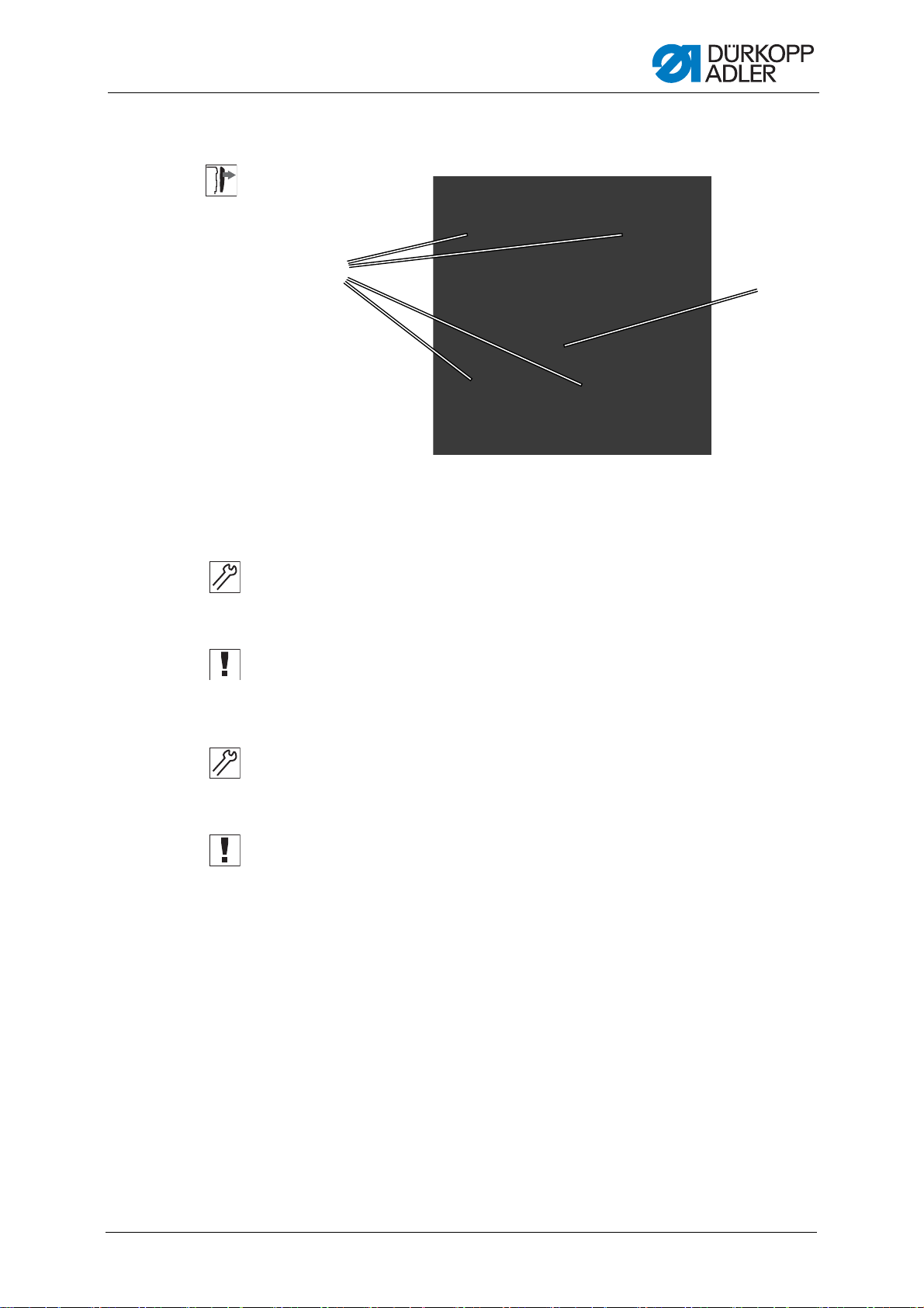
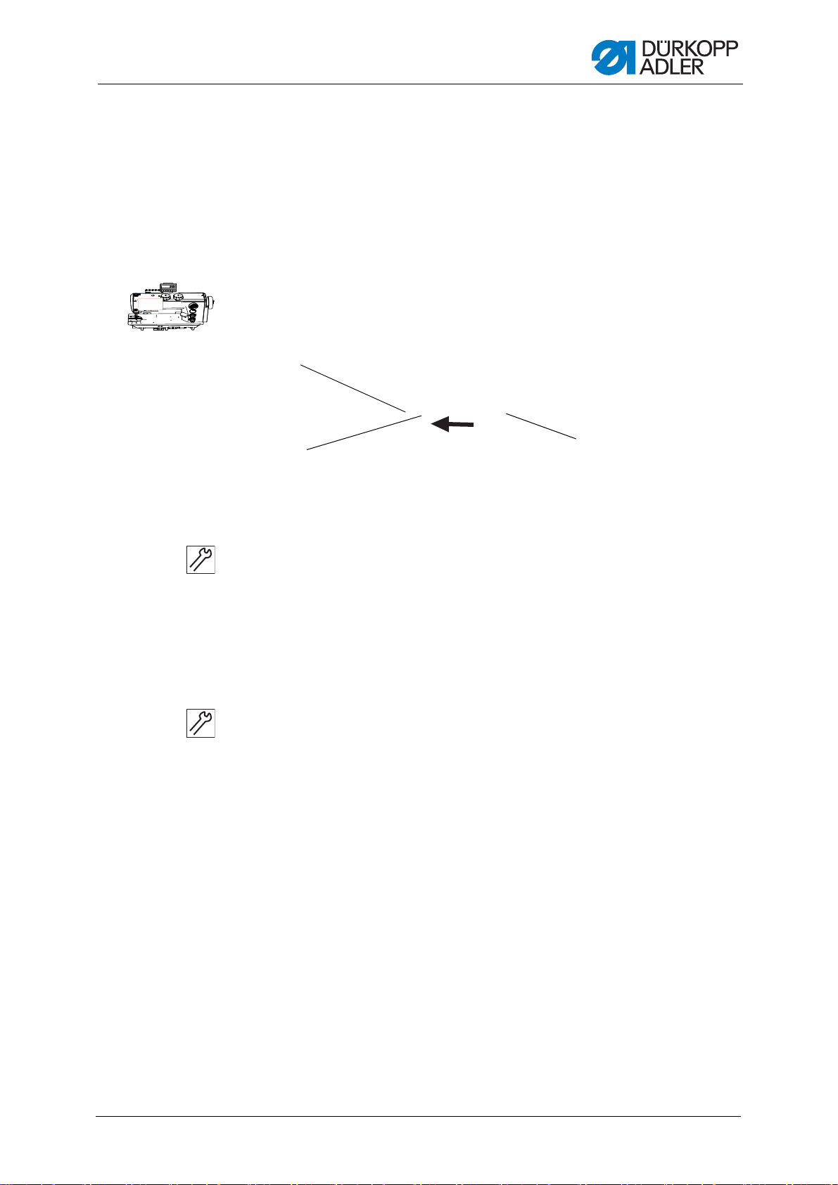
3.3.1 Tilting and erecting the machine head
To access the components on the underside of the machine, swivel up the
machine head.
Fig. 1: Tilting and erecting the machine head
Tilting the machine head
To tilt the machine head:
1. Tilt the machine head as far as it will go.
Erecting the machine head
To erect the machine head:
1. Erect the machine head.
10 Service Instructions 667 - 00.0 - 04/2016
Page 13

Working basis
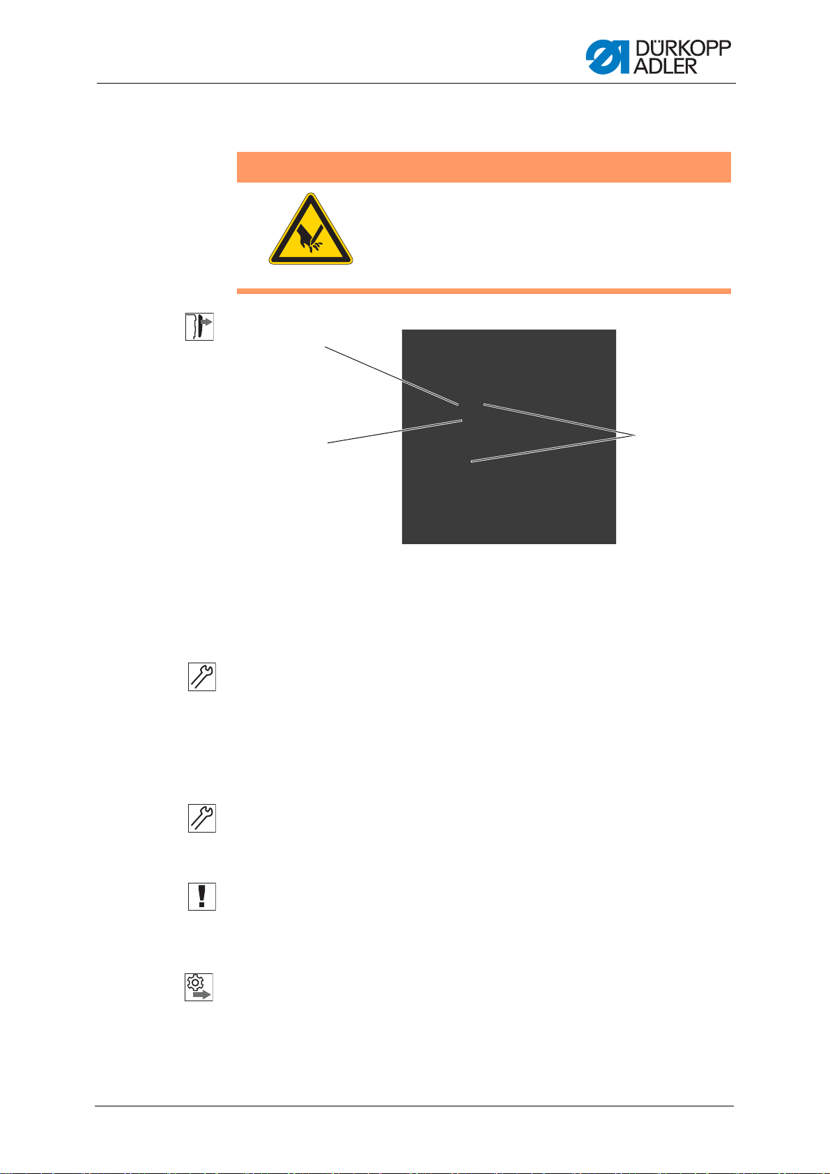
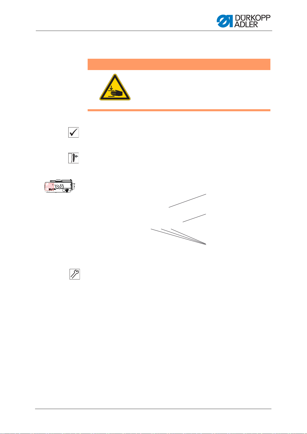
(1) - Screws
(2) - Left adjusting wheel for sewing
foot stroke
(3) - Arm cover
②
③
①
3.3.2 Removing and placing the arm cover
Fig. 2: Removing and placing the arm cover
Removing the arm cover
To remove the arm cover:
1. Position the left adjusting wheel for the sewing foot stroke (2) to 2.
2. Loosen the screws (1).
3. Hold the arm cover (3) at the adjusting wheels and remove it.
Placing the arm cover
To place the arm cover:
1. Position the left adjusting wheel for the sewing foot stroke (2) to 2.
2. Place the arm cover (3).
3. Tighten the screws (1).
Service Instructions 667 - 00.0 - 04/2016 11
Page 14

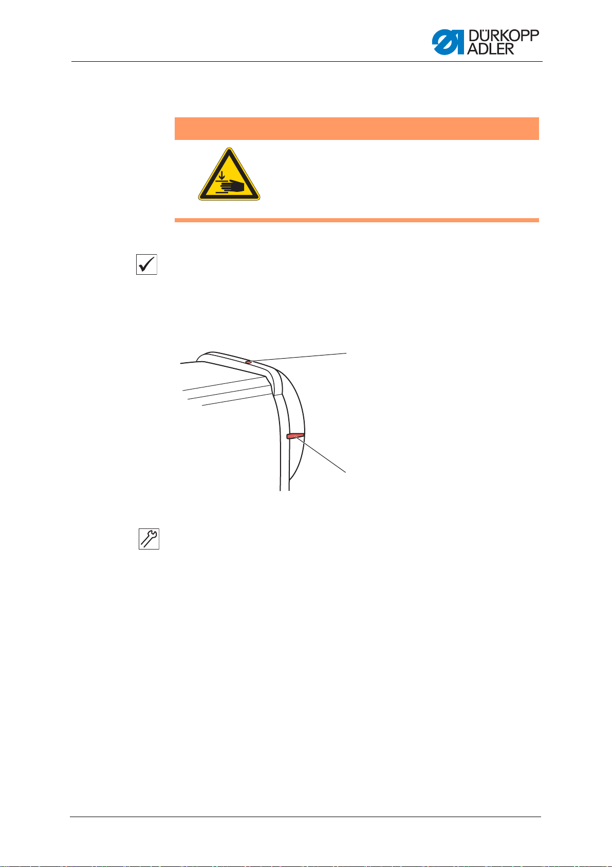
3.3.3 Removing and placing the head cover
(1) - Screws (2) - Head cover
②
①
Fig. 3: Removing and placing the head cover
Working basis
Removing the head cover
To remove the head cover:
1. Loosen the screws (1).
2. Remove the head cover (2).
Placing the head cover
To place the head cover:
1. Place the head cover (2).
2. Tighten the screws (1).
12 Service Instructions 667 - 00.0 - 04/2016
Page 15
Working basis
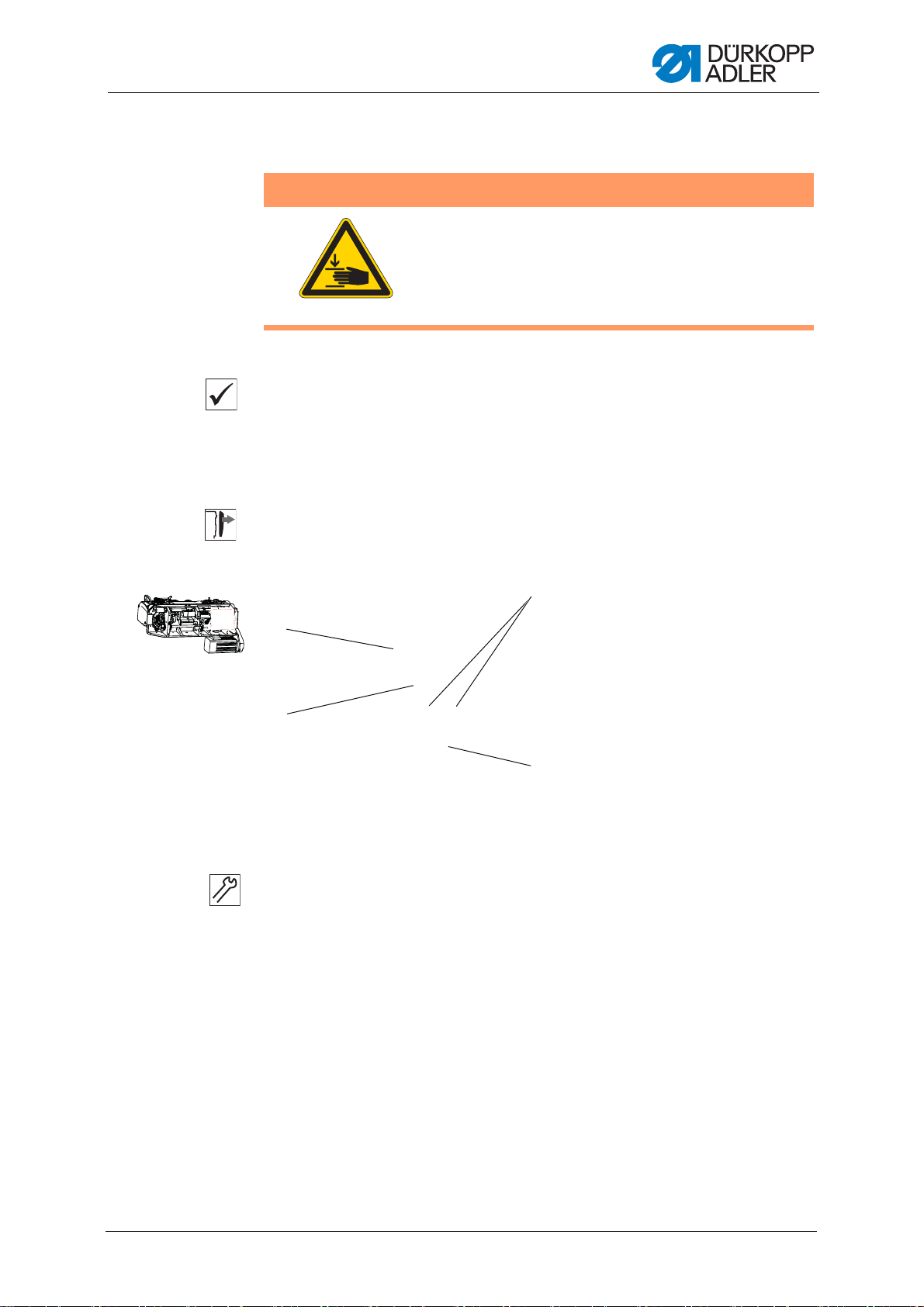
(1) - Screws (2) - Valve cover
②
①
3.3.4 Removing and placing the valve cover
Fig. 4: Removing and placing the valve cover
Removing the valve cover
To remove the valve cover:
1. Loosen all 4 screws (1).
2. Remove the valve cover (2).
Important
When removing the valve cover, be sure not to pull off any cables.
Placing the valve cover
To place the valve cover:
1. Place the valve cover (2).
2. Tighten all 4 screws (1).
Important
When placing the valve cover, be sure not to pull off any cables.
Service Instructions 667 - 00.0 - 04/2016 13
Page 16

3.3.5 Removing and installing the throat plate
(1) - Screws (2) - Throat plate
①
②
WARNING
Risk of injury from sharp and moving parts!
Crushing and puncture possible.
Switch off the machine before you remove or install
the throat plate.
Fig. 5: Removing and installing the throat plate
Working basis
Removing the throat plate
To remove the throat plate:
1. Loosen the screws (1).
2. Remove the throat plate (2).
Installing the throat plate
To install the throat plate:
1. Insert the throat plate (2).
2. Tighten the screws (1).
14 Service Instructions 667 - 00.0 - 04/2016
Page 17
Working basis
①
②
③
3.3.6 Removing and installing the feed dog
WARNING
Risk of injury from sharp and moving parts!
Crushing and puncture possible.
Switch off the machine before you remove or install
the feed dog.
Fig. 6: Removing and installing the feed dog
(1) - Feed dog (2) - Feed dog carrier
(3) - Screws
Removing the feed dog
To remove the feed dog:
1. Tilt the machine head.
2. Loosen the screws (3).
3. Take the feed dog (1) off the feed dog carrier (2).
Installing the feed dog
To install the feed dog:
1. Place the feed dog (1) onto the feed dog carrier (2).
2. Tighten the screws (3).
Important
Check the feed dog position in its movement at maximum stitch length
(depending on the equipment: 6, 9 or 12) by turning the handwheel.
The feed dog must not hit against the throat plate.
Order
Then check the following setting:
• Feed dog ( p. 36)
Service Instructions 667 - 00.0 - 04/2016 15
Page 18
Working basis
2
1
(1) - Flat (2) - Shaft
(1) - Arresting pin
(2) - Large arresting groove
(3) - Small arresting groove
(4) - Arm shaft crank
①
②
③
5 mm
3 mm
④
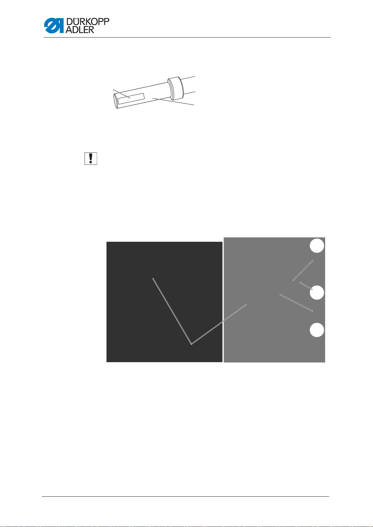
3.4 Flats on shafts
Fig. 7: Flats on shafts
Some shafts have flat surfaces at the points where the components are
screwed on. This stabilizes the connection and makes adjustment easier.
Important
Always ensure that the screws are completely flush with the surface.
3.5 Locking the sewing machine in place
For some settings, the machine must be locked in place. To do this, the
arresting pin from the accessory pack is inserted into a slot on the arm
shaft crank, blocking the arm shaft.
Fig. 8: Locking the sewing machine in place (1)
16 Service Instructions 667 - 00.0 - 04/2016
Page 19
Working basis
(1) - Slot
(2) - Locking opening
(3) - Arresting pin
①
②
③
There are 2 securing positions:
• Position 1: Loop stroke position
• 5 mm end in the large slot
• Setting the loop stroke and needle bar height
• Position 2: Handwheel zero position
• 3 mm end in the small slot
• Setting the handwheel position and checking the top dead center
for the needle bar
Fig. 9: Locking the sewing machine in place (2)
Locking the machine in place
1. Remove the plug from the locking slot (2).
2. Turn the handwheel until the appropriate groove (1) is in front of the
locking opening (2):
• Small slot at handwheel position 0°
• Large groove at handwheel position 200 – 205°
3. Insert the arresting pin (3) with the appropriate end in the groove (1).
Removing the positional lock
1. Pull the arresting pin (3) out of the groove (1).
2. Insert the plug into the locking opening (2).
Service Instructions 667 - 00.0 - 04/2016 17
Page 20

Working basis
(1) - Graduated
scale
(2) - Marking
①
②
3.6 Setting the handwheel into position
For some settings, the graduated scale on the handwheel has to be moved
to a certain position.
Fig. 10: Setting the handwheel into position
To set the handwheel into position:
1. Turn the handwheel until the specified number on the graduated
scale (1) is next to the marking (2).
18 Service Instructions 667 - 00.0 - 04/2016
Page 21
Positioning the arm shaft
(1) - Arm shaft crank
(2) - Machine casting
(3) - Threaded pins
4 Positioning the arm shaf t
Proper setting
The 3 threaded pins (3) on the arm shaft crank (1) are seated completely
on the flat. The arm shaft crank (1) is flush with the machine casting (2).
Cover
• Arm cover ( p. 11)
Fig. 11: Positioning the arm shaft
WARNING
Risk of injury from moving parts!
Crushing possible.
Switch off the machine before you check and set
the position of the arm shaft crank.
1
2
3
To position the arm shaft:
1. Loosen all threaded pins (3) on the arm shaft crank (1).
2. Turn the arm shaft crank (1) such that the threaded pins (3) are seated
completely on the flat of the arm shaft.
3. Push the arm shaft (1) to the right as far as it will go and flush with the
machine casting.
4. Tighten all the threaded pins (3) on the arm shaft crank (1).
Service Instructions 667 - 00.0 - 04/2016 19
Page 22

Positioning the arm shaft
20 Service Instructions 667 - 00.0 - 04/2016
Page 23
Setting the handwheel scale
(1) - Screw opening (2) - Marking
5 Setting the handwheel scale
Checking the proper setting
1. Lock the machine in place at position 2 ( p. 16).
The handwheel is at position 0°.
If a different degree number is next to the marking (2) then you will
have to reset the graduated scale.
Fig. 12: Setting the handwheel scale
WARNING
Risk of injury from moving parts!
Crushing possible.
Switch off the machine before you check and set
the position of the handwheel on the arm shaft.
1
2
To set the handwheel scale:
The handwheel is fastened using 2 threaded pins, which you can see
through the screw opening (1).
1. Turn handwheel until the first threaded pin is under the opening (1).
2. Loosen the threaded pin through the opening (1).
3. Turn the handwheel by 50° such that the second threaded pin is under
the opening (1).
4. Loosen the threaded pin through the opening (1).
5. Lock the machine in place at position 2 ( p. 16).
6. Turn the handwheel scale so that the 0° is at the center of the
marking (2).
7. Tighten the threaded pin through the opening (1).
8. Removing the lock ( p. 16).
9. Move the handwheel into the 50° position.
10. Tighten the threaded pin through the opening (1).
Service Instructions 667 - 00.0 - 04/2016 21
Page 24

Setting the handwheel scale
22 Service Instructions 667 - 00.0 - 04/2016
Page 25

Positioning the toothed belt wheels
6 Positioning the toothed belt wheels
The two toothed belt wheels must be positioned one on top of the other
such that the toothed belt can run correctly. In machines with normal
lengths, the winder wheel is directly next to the upper toothed belt wheel
and determines its alignment. In long arm machines, the winder wheel is
fastened farther away in the center of the arm.
Order
• Always check the position of the other toothed belt wheel after making a
change on either of the toothed belt wheels.
The position of the upper toothed belt wheel is defined by the distance to
the winder wheel.
Therefore, you must first align the upper toothed belt wheel on the winde r
wheel and then align the lower toothed belt such that the toothed belt runs
correctly over both wheels.
6.1 Setting the upper toothed belt wheel
WARNING
Risk of injury from moving parts!
Crushing possible.
Switch off the machine before you check and set
the upper toothed belt wheel.
Proper setting
The 2 threaded pins for the upper toothed belt wheel are seated flush on
the flat.
The distance between the winder wheel and the upper toothed belt wheel
is 0.8 mm.
Cover
• Arm cover ( p. 11)
Service Instructions 667 - 00.0 - 04/2016 23
Page 26

Positioning the toothed belt wheels
3
4
5
2
1
(1) - Upper toothed belt wheel
(2) - Threaded pins
(3) - Winder wheel (position in machines
with normal lengths)
(4) - Toothed belt
(5) - Surface of arm shaft
Fig. 13: Setting the upper toothed belt wheel
To set the upper toothed belt wheel:
1. Using the screwdriver, push the toothed belt (4) sufficiently far to the
side so that the 2 threaded pins (2) can be reached.
2. Loosen the threaded pins (2).
3. Turn the upper toothed belt wheel (1) such that the threaded pins (2)
are seated flush on the flat (5) of the arm shaft.
4. Move the upper toothed belt wheel (1) to the side such that the dista nce
to the winder wheel (3) is 0.8 mm.
5. Tighten the threaded pins (2).
6. Use the screwdriver to push the toothed belt (4) back again.
24 Service Instructions 667 - 00.0 - 04/2016
Page 27
Positioning the toothed belt wheels
2
1
3
4
(1) - Toothed belt
(2) - Retaining ring
(3) - Lower toothed belt wheel
(4) - Threaded pins
6.2 Setting the lower toothed belt wheel
Proper setting
The 2 threaded pins for the lower toothed belt wheel are seated flush on
the flat of the lower shaft.
The toothed belt runs correctly without running against the retaining ring
or slipping off.
Cover
• Tilt the machine head ( p. 10)
WARNING
Risk of injury from moving parts!
Crushing possible.
Switch off the machine before you check and set
the lower toothed belt wheel.
Fig. 14: Setting the lower toothed belt wheel
To set the lower toothed belt wheel:
1. Loosen the threaded pins (4).
2. Turn the lower toothed belt wheel (3) such that the threaded pins (4)
are seated on the flat of the arm shaft.
3. Move the lower toothed belt wheel (3) sufficiently far to the side so that
the toothed belt (1) makes contact with the retaining ring (2) without
being pushed away.
4. Tighten the threaded pins (4).
Service Instructions 667 - 00.0 - 04/2016 25
Page 28

Positioning the toothed belt wheels
26 Service Instructions 667 - 00.0 - 04/2016
Page 29

Setting the stitch length adjusting wheels
0
1
2
4
3
5
6
7
8
9
10
11
12
0
1
2
4
3
5
6
7
8
9
10
11
12
+/–+/–
3
1
2
(1) - Button for the stitch length
on the machine arm
(2) - Upper stitch length adjusting wheel
(3) - Lower stitch length adjusting wheel
7 Setting the stitch length adjusting wheels
Fig. 15: Setting the stitch length adjusting wheels
The 2 adjusting wheels on the machine column determine the stitch length.
• Upper adjusting wheel: larger stitch length
• Lower adjusting wheel: smaller stitch length
It is not possible to set a larger stitch length on the lower adjusting wheel
than on the upper adjusting wheel.
To switch over between the stitch lengths: Press the button for the stitch
length on the machine arm (1).
If the upper adjusting wheel is activated, then the button (1) lights up.
Upon switching on the machine, the stitch length adjusting wheel activated
most recently is always active.
An automatic switchover to the upper adjusting wheel is made when you
switch off the machine at the main switch.
Order
Set the upper stitch length adjusting wheel first, then the lower stitch length
adjusting wheel.
Service Instructions 667 - 00.0 - 04/2016 27
Page 30

Setting the stitch length adjusting wheels
(1) - Upper stitch length adjusting wheel
(2) - Screw
(3) - Lower stitch length adjusting wheel
(4) - Adjusting mark
(5) - Shaft
(6) - Scale
(7) - Wrench
②
①
④
③
⑤
⑥
⑦
7.1 Setting the upper stitch length adjusting wheel
WARNING
Risk of injury from moving parts!
Crushing possible.
Switch off the machine before you set the upper
toothed belt wheel.
Proper setting
Upper stitch length adjusting wheel to 0:
No play on the stitch regulator gear. The plates for the gear are parallel;
the frame cannot be moved.
Cover
• Tilt the machine head ( p. 10)
To set the upper stitch length adjusting wheel:
1. Switch off the machine at the main switch.
The machine switches over to the upper stitch length adjusting
wheel.
Fig. 16: Setting the upper stitch length adjusting wheel (1)
2. Hold the upper stitch length adjusting wheel (1) in place using a
wrench (7).
3. Loosen the screw (2).
4. Remove the upper stitch length adjusting wheel (1) from the shaft (5).
28 Service Instructions 667 - 00.0 - 04/2016
Page 31

Setting the stitch length adjusting wheels
(8) - Frame for the stitch regulator gear
(9) - Plates for the stitch regulator gear
(10) - Hole
(11) - Tension spring
(12) - Screw
⑨
⑧
⑪⑩ ⑫
NOTICE
Property damage may occur!
Risk of machine damage if the shaft is turned too hard.
If you turn the shaft too far, parts on the stitch regulator gear may
bend or get stuck.
Turn the shaft carefully and stop as soon as you feel a slight
resistance.
5. Carefully turn the shaft (5) clockwise using a size 10 wrench.
Fig. 17: Setting the upper stitch length adjusting wheel (2)
6. Check whether the frame (8) for the stitch regulator gear can be moved.
Information
In machines that have a stitch adjustment lever, check this by pressing
the stitch adjustment lever.
In machines that do not have a stitch adjustment lever, insert the arresting pin or a hex key into the opening (10) and try to move the frame (8) up
and down.
7. As soon as the frame (8) stops moving: Remove the wrench from the
shaft (5).
8. Turn the scale (6) so that the 0 is exactly next to the adjusting mark (4).
9. Place the upper stitch length adjusting wheel (1) onto the shaft (5) and
tighten it with a wrench (7).
10. Tighten the upper stitch length adjusting wheel (1) using screw (2).
11. Check whether the plates for the stitch regulator gear (9) are parallel
to one another.
Service Instructions 667 - 00.0 - 04/2016 29
Page 32

Setting the stitch length adjusting wheels
(1) - Button for the stitch length
on the machine arm
(2) - Upper stitch length adjusting wheel
(3) - Lower stitch length adjusting wheel
+/–
Important
If the plates (8) are not parallel to one another:
12. Remove the tension spring (11).
13. Loosen the screw (12).
14. Manually position the plates (9) so that they are parallel.
15. Tighten the screw (12).
16. Attach the tension spring (11).
7.2 Setting the lower stitch length adjusting wheel
WARNING
Risk of injury from moving parts!
Crushing possible.
The lower stitch length adjusting wheel has to be
set when the machine is switched on because
a switchover is automatically made to the upper
stitch length adjusting wheel when the machine is
switched off.
Carry out all work with extreme caution.
Checking the proper setting
Sewing with 2 different stitch lengths:
• The stitch lengths on the seam correspond with the set stitch lengths.
• The lower stitch length adjusting wheel can only be turned up to the
stitch length set on the upper stitch length adjusting wheel.
Cover
• Tilt the machine head ( p. 10)
Fig. 18: Setting the lower stitch length adjusting wheel (1)
0
1
2
3
4
5
6
7
9
8
3
2
4
5
6
7
8
9
10
11
2
3
1
12
11
10
1
+/–
0
12
30 Service Instructions 667 - 00.0 - 04/2016
Page 33

Setting the stitch length adjusting wheels
(1) - Upper stitch length adjusting wheel
(2) - Screw
(3) - Lower stitch length adjusting wheel
(4) - Adjusting mark
(5) - Shaft
(6) - Scale
(7) - Wrench
②
①
④
③
⑤
⑥
⑦
To set the lower stitch length adjusting wheel:
1. Position the upper stitch length adjusting wheel (2) > 3.
2. Switch the machine to short stitch length.
The button for the stitch length (1) does not light up.
If the button lights up, press button (1) again.
Fig. 19: Setting the lower stitch length adjusting wheel (2)
3. Hold the lower stitch length adjusting wheel (3) in place using the
wrench (7).
4. Loosen the screw (2).
5. Remove the lower stitch length adjusting wheel (3) from the shaft (5).
NOTICE
Property damage may occur!
Risk of machine damage if the shaft is turned too hard.
If you turn the shaft too far, parts on the stitch regulator gear may
bend or get stuck.
Turn the shaft carefully and stop as soon as you feel a slight
resistance.
6. Carefully turn shaft (5) clockwise with a size 10 wrench until you feel
significant play on the frame for the stitch regulator gear.
7. Carefully turn shaft (5) counterclockwise with a size 10 wrench until
you no longer feel any play.
8. As soon as the frame stops moving: Remove the wrench from the
shaft (5).
9. Turn the scale (6) so that the 0 is exactly next to the adjusting mark (4).
10. Place the lower stitch length adjusting wheel (3) onto the shaft (5) and
tighten it with a wrench (7).
11. Tighten the lower stitch length adjusting wheel (3) using screw (2).
Service Instructions 667 - 00.0 - 04/2016 31
Page 34

Setting the stitch length adjusting wheels
2
3
1
(1) - Upper stitch length adjusting wheel
(2) - Screw
(3) - Mark-off openings
7.3 Setting the stitch length limit
If not all of the stitch lengths are available during sewing operation, a limit
can be placed on the maximum stitch length that can be set.
WARNING
Risk of injury from moving parts!
Crushing possible.
Switch off the machine before setting the maximum
stitch length limit.
9 or 6 mm can be selected as the maximum stitch length. The appropriate
throat plate must be selected for the selected maximum stitch length.
The throat plate cut-out must be large enough to prevent the feed dog
from hitting the edges of the throat plate at the front and rear d ead center.
NOTICE
Property damage may occur!
Risk of damaging the feed dog due to incorrect throat plate size.
If the throat plate cut-out is too small, the feed dog may hit against
the edges.
Make sure that an appropriate throat plate is used for the selected
maximum stitch length.
Proper setting
Turn the upper stitch length adjusting wheel clockwise as far as it will go.
The upper stitch length adjusting wheel can only be turned up to the
set maximum stitch length.
Fig. 20: Setting the stitch length limit
32 Service Instructions 667 - 00.0 - 04/2016
Page 35

Setting the stitch length adjusting wheels
To set the stitch length limit:
1. Position the upper stitch length adjusting wheel (1) to 0.
2. Hold the upper stitch length adjusting wheel (1) in place using a wrench.
3. Loosen the screw (2).
4. Remove the upper stitch length adjusting wheel (1).
5. Loosen the threaded pin from one of the 3 mark-off openings (3).
6. Screw the threaded pin into the mark-off opening for the required maximum stitch length. The openings are marked with numbers for the
stitch length.
7. Turn the scale so that the 0 is exactly next to the adjusting mark.
8. Place the upper stitch length adjusting wheel (1) and hold it in position
using a wrench.
9. Tighten the screw (2).
7.4 Setting the eccentric for the forward and backward
stitches
WARNING
Risk of injury from moving parts!
Crushing possible.
Switch off the machine before setting the eccentric
screw.
Proper setting
The forward and backward stitches are the same length.
As a test, sew a seam forward, stop, and sew a seam backward. The inser-
tions of the forward and backward stitches have to lie within one another.
Cover
• Tilt the machine head ( p. 10)
Service Instructions 667 - 00.0 - 04/2016 33
Page 36

Setting the stitch length adjusting wheels
2
4
3
1
2
(1) - Block
(2) - Threaded pin
(3) - Eccentric
(4) - Recess
Fig. 21: Setting the eccentric for the forward and backward stitches
To set the eccentric for forward and backward stitches:
1. Loosen the threaded pin (2).
2. Turn the eccentric screw (3) from the right through the opening in the
base plate:
Initial position:
The slot in the eccentric screw (3) is parallel to the threaded pin (2),
the recess (4) faces the front.
If the forward and backward stitches are not the same length:
• Turn clockwise:
The forward stitch becomes larger, the backward stitch smaller.
• Turn counterclockwise:
The forward stitch becomes smaller, the backward stitch larger.
3. Tighten the threaded pin (2).
34 Service Instructions 667 - 00.0 - 04/2016
Page 37

Setting the feed dog
8 Setting the feed dog
The position and the movement of the feed dog and needle bar have to be
coordinated such that the needle pierces exactly in the center of the needle hole of the feed dog.
Order
First, check the following setting:
• Needle bar linkage ( p. 43)
8.1 Setting the feed dog position
WARNING
Risk of injury from moving parts!
Crushing possible.
Switch off the machine before you set the feed dog
position.
Proper setting
The feed dog is exactly in the center of the throat plate cut-out, both sideways and in the sewing direction.
If the stitch length is 0, the needle pierces exactly in the center of the ne edle hole.
Various settings can be made depending on how far the position of the
feed dog differs from the correct setting:
• For minimal deviations, it suffices to move the feed dog on the carrier
( p. 36).
• If this is not sufficient, move the entire feed dog carrier on the sliding
shaft ( p. 36).
Service Instructions 667 - 00.0 - 04/2016 35
Page 38

8.1.1 Moving the feed dog
①
②
③
Cover
• Throat plate ( p. 14)
Fig. 22: Moving the feed dog
Setting the feed dog
(1) - Feed dog
(2) - Feed dog carrier
To move the feed dog:
1. Loosen the screws (3).
2. Move the feed dog (1) on the feed dog carrier (2).
Place the removed throat plate next to it as an aid for orientation so
that the feed dog can be screwed on straight.
3. Tighten the screws (3).
(3) - Screws
36 Service Instructions 667 - 00.0 - 04/2016
Page 39

Setting the feed dog
①
⑧
②
③
④
⑤
⑥
⑦
8.1.2 Moving the feed dog carrier
The feed dog carrier is connected to the stitch regulator gear via the sliding
shaft, and can be moved on this shaft.
Cover
• Tilt the machine head ( p. 10)
Fig. 23: Moving the feed dog carrier
(1) - Adjusting rings
(2) - Threaded pins
(3) - Lever
(4) - Stroke eccentric
To move the feed dog carrier:
1. Position the upper stitch length adjusting wheel to 0.
2. Loosen threaded pins (2), (5), (7) and screw (6).
3. Move the feed dog carrier perpendicular to the sewing direction so that
the feed dog is exactly in the center of the throat plate cut-out.
4. Push the adjusting rings (1) toward each other as far as they will go.
Important
Make sure that the sliding shaft (8) is tightened by the clamping rings.
5. Tighten the threaded pins (2).
6. Tighten the threaded pins (5) for the stroke eccentric (5).
7. The stroke eccentric (4) and the slot of the lever (3) must be in a line.
8. Move the feed dog carrier in the sewing direction such that the feed
dog is exactly in the center of the throat plate cut-out.
9. Tighten screw (6) and threaded pin (7).
In the process, make sure that the feed dog height has the correct set-
ting ( p. 39).
(5) - Threaded pins
(6) - Screw
(7) - Threaded pins
(8) - Sliding shaft
Service Instructions 667 - 00.0 - 04/2016 37
Page 40

Setting the feed dog
(1) - Pusher eccentric
(2) - Threaded pins
(3) - Connecting rod
①
②
③
8.2 Setting the feed dog movement
The feed dog moves in an elliptical cycle. To align this correctly, the feed
movement and the stroke height and the stroke movement of the feed dog
all have to be set.
Order
First, check the following setting:
• Feed dog ( p. 35)
8.2.1 Setting the feed movement
WARNING
Risk of injury from moving parts!
Crushing possible.
Switch off the machine before you check and set
the feed movement of the feed dog.
The proper setting for the feed movement is checked at standstill and set
using the pusher eccentric.
Proper setting
Lock the machine in place at position 1 and position the upper stitch length
wheel to stitch length 0.
The slots of the feed dog eccentric and of the connecting rod are in a
line.
Cover
• Tilt the machine head ( p. 10)
Fig. 24: Setting the feed movement
38 Service Instructions 667 - 00.0 - 04/2016
Page 41

Setting the feed dog
(1) - Stroke eccentric
(2) - Threaded pins
(3) - Lever
(4) - Locking ring
①
②
③
④
To set the feed movement:
1. Position the upper stitch length adjusting wheel to 0.
2. Lock the machine in place at position 1.
3. Loosen the threaded pins (2) on the pusher eccentric (1).
4. Turn the pusher eccentric (1) such that the slot is in a line with the slot
of the connecting rod.
5. Tighten the threaded pins (2).
8.2.2 Setting the feed dog height at top dead center
WARNING
Risk of injury from moving parts!
Crushing possible.
Switch off the machine before you check and set
the feed dog height.
The feed dog reaches the maximum stroke height at top dead center when
the handwheel is positioned at 190°.
Proper setting
Place the feed dog in the uppermost position by turning the handwheel.
The upper edge of the feed dog protrudes 0.5 mm above the throat
plate.
Cover
• Tilt the machine head ( p. 10)
Fig. 25: Setting the feed dog height at top dead center
Service Instructions 667 - 00.0 - 04/2016 39
To set the feed dog height at top dead center:
1. Position the upper stitch length adjusting wheel to 0.
2. Place the feed dog in the uppermost position by turning the handwheel.
Page 42

Setting the feed dog
(1) - Stroke eccentric (2) - Lever
(3) - Stroke eccentric
①
②
③
3. Loosen the threaded pins (2).
4. Turn the stroke eccentric (1) such that the upper edge of the feed dog
protrudes 0.5 mm above the throat plate.
5. Move the stroke eccentric (1) to the left such that the feed dog has no
play in relation to the lever (3).
6. Tighten the threaded pins (2).
8.2.3 Setting the stroke movement
WARNING
Risk of injury from moving parts!
Crushing possible.
Switch off the machine before you check and set
the stroke movement of the feed dog.
Order
First, check the following setting:
• Feed dog height ( p. 39)
Proper setting
Machine locked in place at position 1 and upper stitch length adjusting
wheel set to 0.
Cover
• Tilt the machine head ( p. 10)
Fig. 26: Setting the stroke movement
To set the feed stroke:
1. Position the upper stitch length adjusting wheel to 0.
2. Lock the machine in place at position 1.
40 Service Instructions 667 - 00.0 - 04/2016
Page 43

Setting the feed dog
3. Loosen the threaded pins (3).
4. Turn the stroke eccentric (1) such that the slot is in a line with the slot
of the lever.
5. Tighten the threaded pins (3).
Service Instructions 667 - 00.0 - 04/2016 41
Page 44

Setting the feed dog
42 Service Instructions 667 - 00.0 - 04/2016
Page 45

Aligning the needle bar linkage
1
2
4
3
(1) - Threaded pins
(2) - Adjusting rings
(3) - Throat plate
(4) - Needle bar linkage
9 Aligning the needle bar linkage
Order
First, check the following setting:
• A straight and undamaged needle must be inserted
( Operating Instructions, chap. Inserting and replacing the needle)
Proper setting
Position the upper and lower stitch length adjusting wheel to 0.
The needle pierces exactly in the center of the feed dog needle hole.
9.1 Moving the needle bar linkage sideways
WARNING
Risk of injury from moving parts!
Crushing possible.
Switch off the machine before aligning the needle
bar linkage sideways.
Cover
• Arm cover ( p. 11)
• Head cover ( p. 12)
Fig. 27: Moving the needle bar linkage sideways (1)
Service Instructions 667 - 00.0 - 04/2016 43
To move the needle bar linkage sideways:
1. Set the upper and lower stitch length adjusting wheel to 0.
2. Loosen the threaded pins (1) on the two adjusting rings (2) at the righthand end of the shaft for the needle bar linkage.
Page 46

Aligning the needle bar linkage
5
6
7
(5) - Arm shaft crank
(6) - Threaded pins
(7) - Thread lever
Fig. 28: Moving the needle bar linkage sideways (2)
3. Loosen both threaded pins (6) on the arm shaft crank (5). Make sure
that the threaded pins stay on the surface.
4. Move the needle bar linkage (4) sideways such that the needle pierces
exactly in the center of the needle hole (3) for the feed dog.
5. Push the two adjusting rings (2) inwards as far as they will go and
tighten them.
6. Tighten the threaded pins (1) on the two adjusting rings (2).
7. Align the thread lever (7) exactly in the middle of the slot.
8. Tighten both threaded pins (6) on the arm shaft crank (5).
Order
Then check the following settings:
• Loop stroke position ( p. 49)
• Distance of the hook to the needle ( p. 47)
44 Service Instructions 667 - 00.0 - 04/2016
Page 47

Aligning the needle bar linkage
(1) - Arm surface
(2) - Center of bolt
(3) - Lever
(4) - Threaded pins
(5) - Screw
①
③
②
④
⑤
9.2 Aligning the needle bar linkage in the sewing direction
Cover
• Valve cover ( p. 13)
• Tilt the machine head ( p. 10)
Fig. 29: Aligning the needle bar linkage in the sewing direction
WARNING
Risk of injury from moving parts!
Crushing possible.
Switch off the machine before you check and set
the position of the needle bar linkage in the sewing
direction.
126,6 mm
Proper setting
Stitch length adjusting wheels to 0.
The lever (3) is positioned such that the distance from the surface of
the arm (1) to the middle of the bolt (2) is 126.6 mm.
To align the needle bar linkage in the sewing direction:
1. Position the lower stitch length adjusting wheel to 0.
2. Position the upper stitch length adjusting wheel to 0.
3. Loosen the threaded pins (4).
4. Loosen the screw (5).
5. Position the lever (3).
6. Tighten the threaded pins (4).
7. Tighten the screw (5).
Service Instructions 667 - 00.0 - 04/2016 45
Page 48

Order
Then check the following setting:
• Loop stroke position ( p. 49)
Aligning the needle bar linkage
46 Service Instructions 667 - 00.0 - 04/2016
Page 49

Position of the hook and needle
10 Position of the hook and needle
10.1 Setting the hook side clearance
Order
First, check the following settings:
• A straight and undamaged needle has been inserted
( Operating Instructions, chap. Inserting and replacing the needle)
• Needle bar linkage ( p. 43)
• Loop stroke position ( p. 49)
WARNING
Risk of injury from moving parts!
Crushing possible.
Switch off the machine before you check and set
the hook side clearance.
NOTICE
Property damage may occur!
Damage to the machine, needle breakage, or thread damage due to
an incorrect clearance between the needle and hook tip.
Check and, if necessary, readjust the distance to the hook tip after
inserting a new needle with a different size.
Proper setting
Machine locked in place at position 1 ( p. 16).
Maximum 0.1 mm distance between the hook tip and the groove for
the needle.
Cover
• Tilt the machine head ( p. 10)
• Throat plate ( p. 14)
• Feed dog ( p. 15)
Service Instructions 667 - 00.0 - 04/2016 47
Page 50

Position of the hook and needle
(1) - Threaded pins
(2) - Slot for screw
(3) - Hook tip
(4) - Needle groove
①
②
③
④
Fig. 30: Setting the hook side clearance
To set the hook side clearance:
1. Position the upper stitch length adjusting wheel to 0.
2. Lock the machine in place at position 1.
3. Remove the middle section from the hook.
4. Loosen the threaded pins (1) through the slot (2).
5. Move the hook sideways such that the distance between the hook
6. Tighten the threaded pins (1).
7. Remove the lock.
st
The 1
tip (3) and the groove for the needle (4) is 0.1 mm at most, without the
hook tip (3) touching the needle.
screw in the direction of rotation is located on the flat.
48 Service Instructions 667 - 00.0 - 04/2016
Page 51

Position of the hook and needle
(1) - Vertical center line of the needle (2) - Hook tip
①
②
10.2 Setting the loop stroke position
The loop stroke is the path length from the lower dead center of the needle
bar up to the position where the hook tip is exactly on the vertical center
line of the groove for the needle.
Fig. 31: Setting the loop stroke position (1)
WARNING
Risk of injury from sharp and moving parts!
Crushing and puncture possible.
Switch off the machine before you check and set
the loop stroke position.
The loop stroke is precisely 2 mm.
Order
First, check the following settings:
• Needle bar linkage ( p. 43)
• A straight and undamaged needle must be inserted
( Operating Instructions, chap. Inserting and replacing the needle)
Proper setting
Machine locked in place at position 1 and stitch length set to 0.
The hook tip (2) points exactly to the vertical center line (1) of the
needle.
Disturbance caused by an incorrect setting
• Missing stitches
Service Instructions 667 - 00.0 - 04/2016 49
Page 52

Cover
(1) - Threaded pins
(2) - Hook tip
(3) - Needle groove
①
③
②
• Tilt the machine head ( p. 10)
• Throat plate ( p. 14)
• Feed dog ( p. 15)
Fig. 32: Setting the loop stroke position (2)
Position of the hook and needle
To set the loop stroke position:
1. Lock the machine in place at position 1 ( p. 16).
2. Position the upper stitch length adjusting wheel to 0.
3. Loosen the threaded pins (1).
4. Turn the hook such that the hook tip (2) points exactly to the vertical
center line of the groove (3).
5. Tighten the threaded pins (1).
6. Remove the lock.
Order
Then check the following settings:
• Timing of cutting by the thread cutter ( p. 65)
50 Service Instructions 667 - 00.0 - 04/2016
Page 53

Position of the hook and needle
1
4
3
2
(1) - Needle bar
(2) - Screw
(3) - Needle groove
(4) - Hook tip
10.3 Setting the needle bar height
Order
First, check the following settings:
• Loop stroke position ( p. 49)
• A straight and undamaged needle must be inserted
( Operating Instructions, chapter Inserting and replacing the needle)
Proper setting
Machine locked in place at position 1 and upper stitch length adjusting
wheel set to 0.
WARNING
Risk of injury from sharp and moving parts!
Crushing and puncture possible.
Switch off the machine before you check and set
the needle bar height.
The hook tip is level with the lower third of the groove on the needle.
Disturbances caused by an incorrect needle bar height
• Damage to the hook tip
• Jamming of the needle thread
• Missing stitches
• Thread breaking
• Needle breakage
Cover
• Head cover ( p. 12)
Fig. 33: Setting the needle bar height
To set the needle bar height:
1. Lock the machine in place at position 1 ( p. 16).
2. Position the upper stitch length adjusting wheel to 0.
Service Instructions 667 - 00.0 - 04/2016 51
Page 54

Position of the hook and needle
3. Loosen the screw (2) of the needle bar (1).
4. Move the height of the needle bar (1) such that the hook tip (4) is in
the middle of the lower third of the groove for the needle.
Important
When doing so, take care not to twist the needle to the side.
The groove (3) must face toward the hook.
5. Tighten the screw (2) for the needle bar (1).
6. Remove the lock ( p. 16).
Order
Then check the following setting:
• Position of the needle guard ( p. 51)
52 Service Instructions 667 - 00.0 - 04/2016
Page 55

Sewing feet
5
6
4
1
2
9
1
2
3
(1) - Presser foot
(2) - Feeding foot
(3) - Adjusting wheels for the sewing foot
stroke
11 Sewing feet
The two adjusting wheels (3) on the machine arm determine how high the
presser foot (1) and feeding foot (2) are raised during the sewing process.
The left adjusting wheel determines the normal sewing foot stroke.
The right adjusting wheel determines the elevated sewing foot stroke.
The elevated sewing foot stroke must not be lower than the normal sewing
foot stroke.
Fig. 34: Sewing feet
NOTICE
Property damage may occur!
Machine can be damaged if the adjusting wheels are forced.
Do not attempt to use force to set a smaller sewing foot stroke at the
right adjusting wheel.
Service Instructions 667 - 00.0 - 04/2016 53
Page 56

Sewing feet
1
2
3
4
(1) - Presser foot
(2) - Feeding foot
(3) - Screw
(4) - Sewing foot lever
11.1 Setting an even sewing foot stroke
WARNING
Risk of injury from sharp and moving parts!
Crushing and puncture possible.
Switch off the machine before you check and set
the sewing foot stroke.
Proper setting
For sewing foot stroke 3, the presser foot and feeding foot are raised by
the same height.
Cover
• Arm cover ( p. 11)
Fig. 35: Setting an even sewing foot stroke
To set the even sewing foot stroke:
1. Set the handwheel to the 0° position.
2. Loosen the screw (3).
3. Lower the presser foot (1) and feeding foot (2) together down to the
throat plate.
Important
While doing so, make sure that the feeding foot is only lowered down to
the throat plate. Do not inadvertently lower the feeding foot through the
throat plate cut-out down to the feed dog.
4. Tighten the screw (3).
54 Service Instructions 667 - 00.0 - 04/2016
Page 57

Sewing feet
2
1
3
(1) - Feeding foot
(2) - Feed dog
(3) - Needle tip
11.2 Setting the stroke movement for the feeding foot
WARNING
Risk of injury from sharp and moving parts!
Crushing and puncture possible.
Switch off the machine before you check and set
the stroke movement for the feeding foot.
In order to ensure a correct feed, the stroke movement for the feeding foot
must be aligned to the stroke movement for the feed dog.
Order
First, check the following settings:
• Feed dog movement ( p. 38)
• Even sewing foot stroke ( p. 54)
Proper setting
Left adjusting wheel for the sewing foot stroke set to 9 and the upper stitch
length adjusting wheel to 0.
The feeding foot (1) touches down exactly on the feed dog (2) when
the downward movement of the needle tip (3) reaches the upper
edge of the feeding foot. This will occur when the handwheel is in the
95° position.
Fig. 36: Setting the stroke movement for the feeding foot (1)
Service Instructions 667 - 00.0 - 04/2016 55
Cover
• Arm cover ( p. 10)
Page 58

Sewing feet
1
2
3
(1) - Stroke eccentric
(2) - Threaded pins
(3) - Threaded pin
Fig. 37: Setting the stroke movement for the feeding foot (2)
Proper setting
The feeding foot reaches the level of the throat plate at the same time as
the following elements:
• The feed dog moving up
• The needle tip moving down
To set the stroke movement for the feeding foot:
1. Screw in the threaded pin (3) so that there is a stroke.
2. Loosen the threaded pins (2).
3. Turn the stroke eccentric (1) such that the feeding foot reaches the
level of the throat plate at the same time as the feed dog and the tip
of the needle.
Important
When doing so, ensure not to move the stroke eccentric (1) laterally on the
axle.
4. Tighten the threaded pins (2).
5. Unscrew the threaded pin (3) far enough so that there is no longer any
contact with the clamp.
56 Service Instructions 667 - 00.0 - 04/2016
Page 59

Sewing feet
1
(1) - Adjusting wheel for the sewing foot pressure
11.3 Setting the sewing foot pressure
The adjusting wheel at the top left of the machine arm determines the
pressure for the sewing feet on the sewing material. The pressure can be
adjusted continuously by turning the adjusting wheel.
The correct pressure depends on the sewing material:
• Lower pressure for soft materials, e. g. silk
• Higher pressure for harder materials, e. g. leather
Proper setting
The sewing material does not slip and is correctly transported.
Fig. 38: Setting the sewing foot pressure
To set the sewing foot pressure:
1. Turn the adjusting wheel for the sewing foot pressure (1):
• greater pressure: turn clockwise
• lower pressure: turn counterclockwise
Service Instructions 667 - 00.0 - 04/2016 57
Page 60

Sewing feet
(1) - Adjusting screw
(2) - Counternut
11.4 Setting the sewing foot lifting height
WARNING
Risk of injury from moving parts!
Crushing possible
The machine must remain switched on so that the
sewing feet can be raised.
Work very carefully when you check and set the
lifting height for the sewing feet.
Do not put your hands under the sewing feet when
they are being lowered.
When the pedal is pressed back halfway, the sewing feet can be raised
during sewing, e. g. to move the sewing material.
When the pedal is pressed completely back, the sewing feet will be raised
after the thread is cut so that the sewing material can be exchanged.
Proper setting
The distance between the raised sewing feet and the throat plate is preset
to 25 mm on delivery.
Fig. 39: Setting the sewing foot lifting height
1
2
Setting steps
1. Loosen the counternut (2) for the adjusting screw (1).
2. Turn the adjusting screw (1) to set the distance between the raised
sewing feet and the throat plate:
• Raise the sewing feet to a lesser height: turn clockwise
• Raise the sewing feet higher: turn counterclockwise
58 Service Instructions 667 - 00.0 - 04/2016
3. Tighten the counternut (2) for the adjusting screw (1).
Page 61

Setting the needle thread tension
+
1234
+
–
2
1
(1) - Needle thread regulator
(2) - Screw
12 Setting the needle thread tension
12.1 Setting the needle thread regulator
The needle thread regulator determines the tension applied to guide the
needle thread around the hook. The required tension depends on the
thickness of the sewing material, thread strength, and stitch length.
Lower thread tension for
• thin sewing material
• low thread strengths
Greater thread tension for
• thick sewing material
• high thread strengths
Proper setting
The loop of the needle thread slides at low tension over the thickest point
of the hook, without forming loops or snagging.
Cover
• Throat plate slide ( p. 14)
Fig. 40: Setting the needle thread regulator
To set the needle thread regulator:
1. Turn the handwhee l and observe the cycle of the needle thread around
the hook.
2. Loosen the screw (2).
3. Moving the needle thread regulator
• Reduce tension: slide to the left
• Increase tension: slide to the right
4. Tighten the screw (2).
Service Instructions 667 - 00.0 - 04/2016 59
Page 62

Setting the needle thread tension
2
3
4
1
(1) - Stop collar
(2) - Spring
(3) - Tension disk
(4) - Screw
12.2 Setting the thread tensioning spring
The thread tensioning spring holds the needle thread under tension from
the top dead center of the thread lever up to the point when the needle eye
plunges into the sewing material.
Proper setting
Initial position: The thread tensioning spring does not contact the stop
until the needle eye has plunged into the sewing material.
Important
The setting for the thread tensioning spring must be varied according to
the sewing material and the required sewing result.
Fig. 41: Setting the thread tensioning spring
To set the thread tensioning spring:
1. Loosen the screw (4).
2. Setting the spring travel: Turn the stop collar (1):
• Longer spring travel: turn counterclockwise
• Shorter spring travel: turn clockwise
3. Setting the spring tension: Turn the tension disk (3):
• Greater spring tension: turn counterclockwise
• Lower spring tension: turn clockwise
Important
Do not twist the stop collar in doing so.
4. Tighten the screw (4).
60 Service Instructions 667 - 00.0 - 04/2016
Page 63

Winder
(1) - Screws
(2) - Screw
(3) - Winder lever
(4) - Arm
13 Winder
13.1 Setting the winder
Proper setting
The winder wheel runs smoothly and without axial play.
The winding process will stop automatically when the required filling quan-
tity of the bobbin is reached.
Cover
• Arm cover ( p. 11)
Removing the winder
Fig. 42: Removing the winder
1
4
2
3
To remove the winder:
1. Loosen the screws (1).
2. Remove the winder.
Setting the winder filling quantity
To set the winder filling quantity:
The position of the arms on the screw (2) determines the filling quantity:
• Parallel: Automatic winding stop at 0.5 mm below the edge of the
winder
• Closer together: Automatic stop with larger filling quantity
• Further apart from each other: Automatic stop with smaller filling
quantity
3. Turn the screw (2):
• Arms closer together: turn counterclockwise
• Arms further apart from each other: turn clockwise
4. Put the completely filled bobbin onto the winder.
5. Fold the winder lever (3) upwards as far as it will go to the thread.
Service Instructions 667 - 00.0 - 04/2016 61
Page 64

Setting the winder spacing
6
^
<
+
5
,
3
(3) - Bobbin lever
(5) - Block
(6) - Winder wheel
(11) - Thread-pulling knife
(12) - Winder spindle
(13) - Right-hand screw hole
(14) - Locking disk
6
8
9
9
0
5
7
(5) - Block
(6) - Winder wheel
(7) - Threaded pin
(8) - Threaded pin
(9) - Switch cam
(10) - Leaf spring
Fig. 43: Setting the winder spacing
To set the winder spacing:
Winder
1. Turn the winder spindle (12) such that the thread-pulling knife (11) is
at the top right and is facing the right-hand screw hole (13).
2. Loosen the threaded pin in the block (5).
3. Set the winder lever (3) such that the upper arm is above the marking
for the XXL hook (15).
The distance between the winder lever and the outer thread on the
bobbin is 2 – 3 mm.
4. Set the block (5) such that it is resting against the locking disk (14).
5. Set the block (5) such that its distance to the winder wheel (6) is 0.5 mm.
6. Tighten the threaded pin in the block (5).
Setting the winder run
Fig. 44: Setting the winder run
62 Service Instructions 667 - 00.0 - 04/2016
Page 65

Winder
(1) - Screws (15) - Marking for XXL hook
To set the winder run:
1. Loosen the threaded pin (8).
2. Set the switch cam (9) such that it is just contacting the leaf spring (10)
when the block (5) has engaged in the locking disk.
3. Set the switch cam (9) such that the winder lever (3) has no axial play.
4. Tighten the threaded pin (8).
Installing the winder
Fig. 45: Installing the winder
1
.
To install the winder:
1. Place the winder on the machine arm.
2. Tighten the screws (1).
Service Instructions 667 - 00.0 - 04/2016 63
Page 66

Winder
2
1
(1) - Screw (2) - Hook thread guide
13.2 Setting the hook thread guide
The position of the hook thread guide determines how the thread is wound
onto the winder.
Proper setting
The thread is wound on evenly over the entire width of the bobbin.
Fig. 46: Setting the hook thread guide
To set the hook thread guide:
1. Loosen the screw (1).
2. Turn the hook thread guide (2):
• To the front: The thread will be wound on further to the front
• To the rear: The thread will be wound on further to the rear
64 Service Instructions 667 - 00.0 - 04/2016
Page 67

Thread cutter
①
②③
14 Thread cutter
WARNING
Risk of injury from sharp and moving parts!
Cutting and crushing possible.
Switch off the machine before setting the thread
cutter.
14.1 Setting the control cam position
Fig. 47: Setting the control cam position
(1) - Hook pinion
(2) - Control cam
Proper setting
The control cam (2) makes contact with the hook pinion (1).
The first screw (3) in the hook's direction of rotation must be located on the
flat of the shaft. This defines the timing of the knife movement.
To set the position of the control cam:
1. Loosen the screw (3) on the control cam (2).
2. Rotate the control cam (2).
The first screw in the direction of rotation is located on the flat of the
shaft.
3. Tighten the screw (3).
Service Instructions 667 - 00.0 - 04/2016 65
(3) - Screw
Page 68

Thread cutter
①
②
③
④⑤
⑥
14.2 Setting the armature of the thread cutter magnet
Fig. 48: Setting the armature of the thread cutter magnet
(1) - Block
(2) - Pull rod
(3) - Roller
Proper setting
When the magnet is at rest, the distance between the roller (3) and the
highest point of the control cam (4) must range between 0.2 and 0.3 mm.
To check the armature of the thread cutter magnet:
1. Slide the pull rod (2) with the block (1) all the way to the left.
2. Check the distance between the roller (3) and the control cam (4) using
a feeler gage.
To set the armature of the thread cutter magnet:
3. Turn the nut (6) on the armature (5).
4. Check the setting and correct it if necessary.
(4) - Control cam
(5) - Armature
(6) - Nut
66 Service Instructions 667 - 00.0 - 04/2016
Page 69

Thread cutter
①③
②
⑥
⑦
④
⑤
14.3 Setting the position of the thread-pulling knife
Fig. 49: Setting the position of the thread-pulling knife (1)
(1) - Tip
(2) - Stationary knife
Fig. 50: Setting the position of the thread-pulling knife (2)
(4) - Block
(5) - Pull rod
(3) - Thread-pulling knife
(6) - Roller
(7) - Screw
Proper setting
When the knife is at rest, the tip (1) of the thread-pulling knife (3) must be
positioned flush below the cutting edge of the stationary knife (2).
To set the position of the thread-pulling knife:
1. Turn the handwheel until the thread lever is positioned slightly beyond
its highest point.
2. Loosen the screw (7).
3. Set the thread-pulling knife (3).
Service Instructions 667 - 00.0 - 04/2016 67
Page 70

Thread cutter
① ②
③
④
⑤
4. Slide the pull rod (5) to the left under slight pressur e to keep the play
inside the mechanics of the thread cutter at a minimum.
5. Position the block (4) with the roller (6) against the control cam.
6. Tighten the screw (7).
7. Check the setting and correct it if necessary.
14.4 Setting the cutting pressure
Fig. 51: Setting the cutting pressure (1)
(1) - Screw (2) - Thread-pulling knife
Fig. 52: Setting the cutting pressure (2)
(3) - Block
(4) - Roller
(5) - Control cam
Proper setting
The thread should be cut at a pressure that is as low as possible.
A low cutting pressure will keep knife wear at a minimum.
Two of the thickest threads used must be reliably cut at the same time.
68 Service Instructions 667 - 00.0 - 04/2016
Page 71

Thread cutter
Important
If the cutting pressure is too high, the thread cut ter magnet will not swivel
out the thread-pulling knife. The thread will not be cut.
To check the cutting pressure:
1. Turn the handwheel until the threa d-pulling knife (2) can be swung out
by hand.
2. To do this, press the block (3) with the roller (4) to the right against the
control cam.
The thread-pulling knife (2) swivels out.
3. Insert 2 threads to be cut into the thread-pulling knife (2).
4. Turn the handwheel further until the thread-pulling knife (2) is swiveled
down.
5. Check whether the threads have been cleanly cut.
To set the cutting pressure:
1. Turn the screw (1).
• greater cutting pressure: turn clockwise
• lower cutting pressure: turn counterclockwise
2. Check the setting and correct it if necessary.
Service Instructions 667 - 00.0 - 04/2016 69
Page 72

Thread cutter
70 Service Instructions 667 - 00.0 - 04/2016
Page 73

Setting the potentiometer
ESC
ABCD
OK
++++
––––
P
RESET
1
2
3
4
5
(1) - ESC button
(2) - P button
(3) - Plus/Minus buttons
(4) - Reset button
(5) - OK button
15 Setting the potentiometer
The potentiometer adjusts the number of stitches to the set sewing foot
stroke and reduces the number of stitches if the sewing foot stroke is too
much.
Proper setting
After accessing the technician level and pressing the OK button, the left
display will show 1 in the first instance and the relevant maximum speed
next to it.
WARNING
Risk of injury from moving parts!
Crushing possible.
Carry out all work with great caution.
Cover
• Arm cover ( p. 11)
Fig. 53: Setting the potentiometer (1)
To set the potentiometer:
1. Switch off the machine at the main switch.
2. Keep the P button (2) and Reset button (3) pressed down simultaneously and switch on the machine at the main power switch in doing so.
Service Instructions 667 - 00.0 - 04/2016 71
The display starts.
3. Release the P button (2) and the reset button (3).
The display indicates the current level.
The potentiometer is set at technician level t 10 04.
If the display indicates a different level:
4. Call up the technician level using the Plus/Minus buttons (3):
As the case may be, press the Plus or Minus button below the letter
or the number until the display indicates t1004.
Page 74

Setting the potentiometer
3
4
1
2
(1) - Threaded pins
(2) - Connecting clamp for lifting cylinder
(3) - Threaded pin for the setting shaft
(4) - Potentiometer
5. Press the OK button (5).
Fig. 54: Setting the potentiometer (2)
6. Check whether the lifting gear plates are flush.
If the plates are not flush:
7. Loosen the threaded pins (1).
8. Set the connecting clamp (2) for the lifting cylinder such that the plates
are flush.
9. Tighten the threaded pins (1).
10. Loosen the threaded pin (3).
11. Turn the potentiometer axle such that the left display shows 1 in the
first instance and the relevant maximum speed next to it.
12. Tighten the threaded pin (3) without changing the value shown in the
display.
13. Press the ESC button two times.
Important
14. Switch off the machine at the main switch.
15. Switch on the m achine at the main switch.
Switching off and on will save the setting.
72 Service Instructions 667 - 00.0 - 04/2016
Page 75

Maintenance
16 Maintenance
This chapter describes maintenance work that needs to be carried out on
a regular basis to extend the service life of the machine and achieve the
desired seam quality.
WARNING
Risk of injury from sharp parts!
Punctures and cutting possible.
Prior to any maintenance work, switch off the
machine or set the machine to threading mode.
WARNING
Risk of injury from moving parts!
Crushing possible.
Prior to any maintenance work, switch off the
machine or set the machine to threading mode.
Maintenance interval
Work to be carried out Operating hours
8 40 160 500
Cleaning
Removing lint and thread remnants
Cleaning the motor fan mesh
Lubricating
Lubricating the machine head
Lubricating the hook
Servicing the pneumatic system
Checking the operating pressure
Draining the water condensation
Cleaning the filter element
Servicing specific components
Checking the toothed belt
Service Instructions 667 - 00.0 - 04/2016 73
Page 76

Maintenance
16.1 Cleaning
16.1.1 Cleaning the machine
Lint and thread remnants should be removed after every 8 operating hours
using a compressed air gun or a brush. If very fluffy sewing material is being sewn the machine must be cleaned more frequently.
WARNING
Risk of injury from flying particles!
Flying particles can enter the eyes, causing injury.
Wear safety goggles.
Hold the compressed air gun so that the particles
do not fly close to people.
Make sure no particles fly into the oil pan.
NOTICE
Property damage from soiling!
Lint and thread remnants can impair the operation of the machine.
Clean the machine as described.
NOTICE
Property damage from solvent-based cleaners!
Solvent-based cleaners will damage paintwork.
Use only solvent-free substances for cleaning.
74 Service Instructions 667 - 00.0 - 04/2016
Page 77

Maintenance
(1) - Area around the needle
(2) - Hook
(3) - Area under the throat plate
(4) - Cutter on the winder
②
③
①
④
(1) - Tabletop (2) - Motor fan mesh
②
①
Fig. 55: Cleaning the machine
Areas particularly susceptible to soiling:
• Cutter on the winder for the hook thread (4)
• Area under the throat plate (3)
• Hook (2)
• Area around the needle (1)
To clean the machine:
1. Remove any dust and thread remnants using a compressed air gun or
a brush.
16.1.2 Cleaning the motor fan mesh
The motor fan mesh must be cleaned once a month using a compressed
air gun. If very fluffy sewing material is being sewn, the motor fan mesh
must be cleaned more frequently.
Fig. 56: Cleaning the motor fan mesh
To clean the motor fan mesh:
Service Instructions 667 - 00.0 - 04/2016 75
1. Remove any sewing dust and thread remnants using a compressed
air gun.
Page 78

16.2 Lubricating
CAUTION
Risk of injuries from contact with oil!
Oil can cause a rash if it comes into contact with
skin.
Avoid skin contact with oil.
If oil has come into contact with your skin, wash the
affected areas thoroughly.
NOTICE
Property damage from incorrect oil!
Incorrect oil types can result in damage to the machine.
Only use oil that complies with the data in the instructions.
Maintenance
CAUTION
Risk of environmental damage from oil!
Oil is a pollutant and must not enter the sewage
system or the soil.
Carefully collect up used oil.
Dispose of used oil and oily machine parts in
accordance with national regulations.
For topping off the oil reservoir, use only lubricating oil DA 10 or oil of
equivalent quality with the following specifications:
Viscosity at 40 °C: 10 mm²/s
• Flash point: 150 °C
You can order the lubricating oil from our sales offices using the following
part numbers:
Container Part no.
250 ml 9047 000011
1 l 9047 000012
2 l 9047 000013
5 l 9047 000014
76 Service Instructions 667 - 00.0 - 04/2016
Page 79

Maintenance
MAX
MIN
(1) - Filler opening
(2) - Minimum level marking
(3) - Maximum level marking
②
③
①
16.2.1 Lubricating the machine head
The central oil lubrication system supplies all bearing positions automatically with oil from the reservoir.
NOTICE
Machine damage possible from incorrect oil level!
Too little or too much oil can cause damage to the machine.
Check the oil level every day and top off the oil if necessary.
Proper setting
The oil level is correct if it is positioned between the minimum and the
maximum marking.
Fig. 57: Lubricating the machine head
To lubricate the machine head:
1. Check the oil level indicator every day.
2. If the oil level is below the minimum level marking (3):
Pour oil through the refill opening (1) but no higher than t he maximum
level marking (2).
Information
Notice for machines with CLASSIC equipment
If the oil level drops below the minimum level marking (3), the oil level indicator lights up red.
1. Turn the sewing machine off, then on again after refilling oil.
The red light will turn off.
Service Instructions 667 - 00.0 - 04/2016 77
Page 80

Maintenance
(1) - Screw
①
16.2.2 Lubricating the hook
WARNING
Risk of injury!
Risk of crushing injuries and stab wounds from
sharp and moving parts.
When holding the blotting paper, make sure it does
not enter the area of the hook or below the needle
and the sewing foot.
Switch the sewing machine off before lubricating
the hook.
The oil quantity necessary for lubricating the hook has been set at the factory. Hold a sheet of blotting paper next to the hook while sewing.
Proper setting
After sewing a stretch of approx. 1 m, the blotting paper will have been
sprayed with a thin and even film of oil.
Cover
• Throat plate ( p. 14)
Fig. 58: Lubricating the hook
To lubricate the hook:
1. Turn the screw (1):
• Counterclockwise: the oil quantity increases
• Clockwise: the oil quantity decreases
Important
Any change in oil quantity will not take effect until the machine has been
in operation for a few minutes. Before checking the setting again, sew for
a few minutes first.
78 Service Instructions 667 - 00.0 - 04/2016
Page 81

Maintenance
①
②
16.3 Servicing the pneumatic system
16.3.1 Setting the operating pressure
NOTICE
Property damage from incorrect setting!
Incorrect operating pressure can result in damage to the machine.
Ensure that the machine is only used when the operating pressure
is set correctly.
Proper setting
Refer to the Technical data ( p. 87) chapter for the permissible operating
pressure. The operating pressure cannot deviate by more than ± 0.5 bar.
Check the operating pressure on a daily basis.
Fig. 59: Setting the operating pressure
(1) - Pressure controller (2) - Pressure gage
To set the operating pressure:
1. Pull the pressure controller (1) up.
2. Turn the pressure controller until the pressure gage (2) indicates the
proper setting:
• Increase pressure = turn clockwise
• Reduce pressure = turn counterclockwise
3. Push the pressure controller (1) down.
Service Instructions 667 - 00.0 - 04/2016 79
Page 82

Maintenance
①
②③
16.3.2 Draining the water condensation
NOTICE
Property damage from excess water!
Excess water can cause damage to the machine.
Drain water as required.
Water condensation accumulates in the water separator (2) of the pressure
controller.
Proper setting
Water condensation must not rise up to the level of the filter element (1).
Check the water level in the water separator (2) on a daily basis.
Fig. 60: Draining the water condensation
(1) - Filter element
(2) - Water separator
To drain water condensation:
1. Disconnect the machine from the compressed air supply.
2. Place the collection tray under the drain screw (3).
3. Loosen the drain screw (3) completely.
4. Allow water to drain into the collection tray.
5. Tighten the drain screw (3).
6. Connect the machine to the compressed air supply.
(3) - Drain screw
80 Service Instructions 667 - 00.0 - 04/2016
Page 83

Maintenance
①
②③
16.3.3 Cleaning the filter element
NOTICE
Damage to the paintwork from solvent-based cleaners!
Solvent-based cleaners damage the filter.
Use only solvent-free substances for washing out the filter tray.
Fig. 61: Cleaning the filter element
(1) - Filter element
(2) - Water separator
To clean the filter element:
1. Disconnect the machine from the compressed air supply.
2. Drain the water condensation ( p. 80).
3. Loosen the water separator (2).
4. Loosen the filter element (1).
5. Blow out the filter element (1) using a compressed air gun.
6. Wash out the filter tray using benzine.
7. Tighten the filter element (1).
8. Tighten the water separator (2).
9. Tighten the drain screw (3).
10. Connect the machine to the compressed air supply.
(3) - Drain screw
Service Instructions 667 - 00.0 - 04/2016 81
Page 84

Maintenance
16.4 Servicing specific components
Checking the toothed belt
WARNING
Risk of injury!
Crushing injuries from moving parts.
Before checking the condition of the toothed belt,
switch off the machine at the main switch.
The condition of the toothed belt must be checked once a month.
Important
A damaged toothed belt must be replaced immediately.
Proper setting
• The toothed belt exhibits no cracks or fragile areas
• When pressed with a finger, the toothed belt must yield no more than
10 mm.
16.5 Parts list
A parts list can be ordered from Dürkopp Adler. Or visit our website for further information at:
www.duerkopp-adler.com
82 Service Instructions 667 - 00.0 - 04/2016
Page 85

Decommissioning
17 Decommissioning
You need to perform a number of activities if the machine is to be shut
down for a longer period of time or completely decommissioned.
WARNING
Risk of injury from a lack of care!
Serious injuries may occur.
ONLY clean the machine when it is switched off.
Allow ONLY trained personnel to disconnect the
machine.
CAUTION
Risk of injuries from contact with oil!
Oil can cause a rash if it comes into contact with
skin.
Avoid skin contact with oil.
If oil has come into contact with your skin, wash the
affected areas thoroughly.
To decommission the machine:
1. Switch off the machine.
2. Unplug the power plug.
3. If applicable, disconnect the machine from the compressed air supply.
4. Remove residual oil from the oil pan using a cloth.
5. Cover the control panel to protect it from soiling.
6. Cover the control to protect it from soiling.
7. Cover the entire machine if possible to protect it from contamination
and damage.
Service Instructions 667 - 00.0 - 04/2016 83
Page 86

Decommissioning
84 Service Instructions 667 - 00.0 - 04/2016
Page 87

Disposal
18 Disposal
The machine must not be disposed of in the normal household waste.
The machine must be disposed of in a suitable and proper manner and in
accordance with all applicable national regulations.
CAUTION
Risk of environmental damage from improper
disposal!
Improper disposal of the machine can result in
serious environmental damage.
ALWAYS comply with the legal regulations
regarding disposal.
When disposing of the machine, be aware that it consists of a range of different materials (steel, plastic, electronic components, etc.). Follow the
applicable national regulations when disposing of these materials.
Service Instructions 667 - 00.0 - 04/2016 85
Page 88

Disposal
86 Service Instructions 667 - 00.0 - 04/2016
Page 89

Technical data
19 Technical data
Data and characteristic values
Technical data Unit Class
Machine type 667
Stitch type Lockstitch 301
Hook type Horizontal hook, Xl or XXL
Number of needles 1
Needle system 134-35
Needle strength [Nm] 80-150, 100-180
Thread strength [Nm] 80/3-15/3
Stitch length [mm] 9
Speed maximum
Speed on delivery
Operating pressure [bar] 6
Length [mm] 630
Width [mm] 255
Height [mm] 420
Weight [kg] 50
-1
[min
[min-1]
]
3000
2800
Characteristics
The machine is equipped with a large or extra large horizontal hook.
The maximum sewing foot lift is 20 mm.
The remaining thread length following the thread cutting process is
approx. 10mm.
A safety friction clutch prevents any misadjustment or damage to the hook
in the event of a thread jamming.
Automatic wick lubrication with an inspection glass housed in the arm for
lubricating the machine and one inspection glass in the base plate for
lubricating the hook.
All subclasses, except for the classes without a thread cutting device, are
equipped with a button bar. An additional button panel has been placed
within easy reach of the sewer and allows the sewer to assign the same
6 functions of the buttons housed in the button bar.
Service Instructions 667 - 00.0 - 04/2016 87
Page 90

Technical data
88 Service Instructions 667 - 00.0 - 04/2016
Page 91

Page 92

DÜRKOPP ADLER AG
Potsdamer Str. 190
33719 Bielefeld
Germany
Phone: +49 (0) 521 925 00
Email: service@duerkopp-adler.com
www.duerkopp-adler.com
Subject to design changes - Part of the machines shown with additional equipment - Printed in Germany
© Dürkopp Adler AG - Service Instructions - 0791 667640 EN - 00.0 - 04/2016
 Loading...