

DURKOPP ADLER H-TYPE Series, H-TYPE ECO Long, H-TYPE CLASSIC, H-TYPE ECO, H-TYPE CLASSIC Long Additional Instructions
Page 1

H-TYPE
Additional Instructions
Replacing the winder
Page 2
IMPORTANT
READ CAREFULLY BEFORE USE
KEEP FOR FUTURE REFERENCE
All rights reserved.
Property of Dürkopp Adler AG and protected by copyright. Any reuse of these contents,
including extracts, is prohibited without the prior written approval of Dürkopp Adler AG.
Copyright © Dürkopp Adler AG 2017
Page 3

Table of Contents
1 General information ...................................................................3
2 Disassembling the old tensioning plate...................................5
3 Assembling the new tensioning plate ...................................... 8
Additional Instructions H-TYPE - 00.0 - 09/2017 1
Page 4

Table of Contents
2 Additional Instructions H-TYPE - 00.0 - 09/2017
Page 5
General information
1 General information
The H-TYPE machines come with a new winder that is part of the tensioning plate. This makes it necessary to change the entire tensioning plate in
order to replace the winder.
Versions of the tensioning plate
The tensioning plate of the H-TYPE machine is available in four versions:
ECO, CLASSIC, ECO Long, CLASSIC Long. You need to select a new
tensioning plate that matches the corresponding machine type
Machine type Part number OLD Part number NEW
:
ECO
CLASSIC
ECO Long
CLASSIC Long
H667 110244 H667 110524
H667 110254 H667 110534
H667 110424 H667 110544
H667 110434 H667 110554
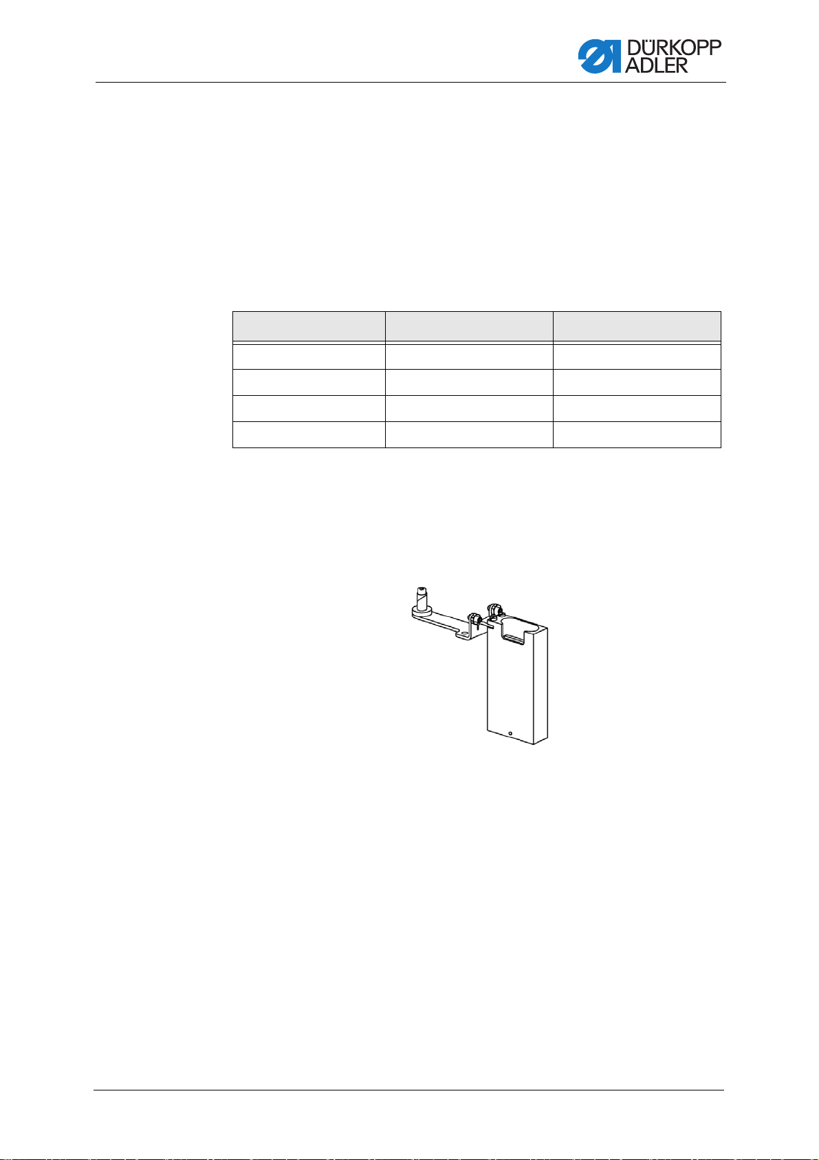
In addition to the new tensioning plate, you MUST order:
• Carrier for the control (H667 170844)
• Connection cable (ECO, CLASSIC - 9870 967009)
(ECO Long, CLASSIC Long - 9870 967010)
Fig. 1: Carrier for the control
Additional Instructions H-TYPE - 00.0 - 09/2017 3
Page 6
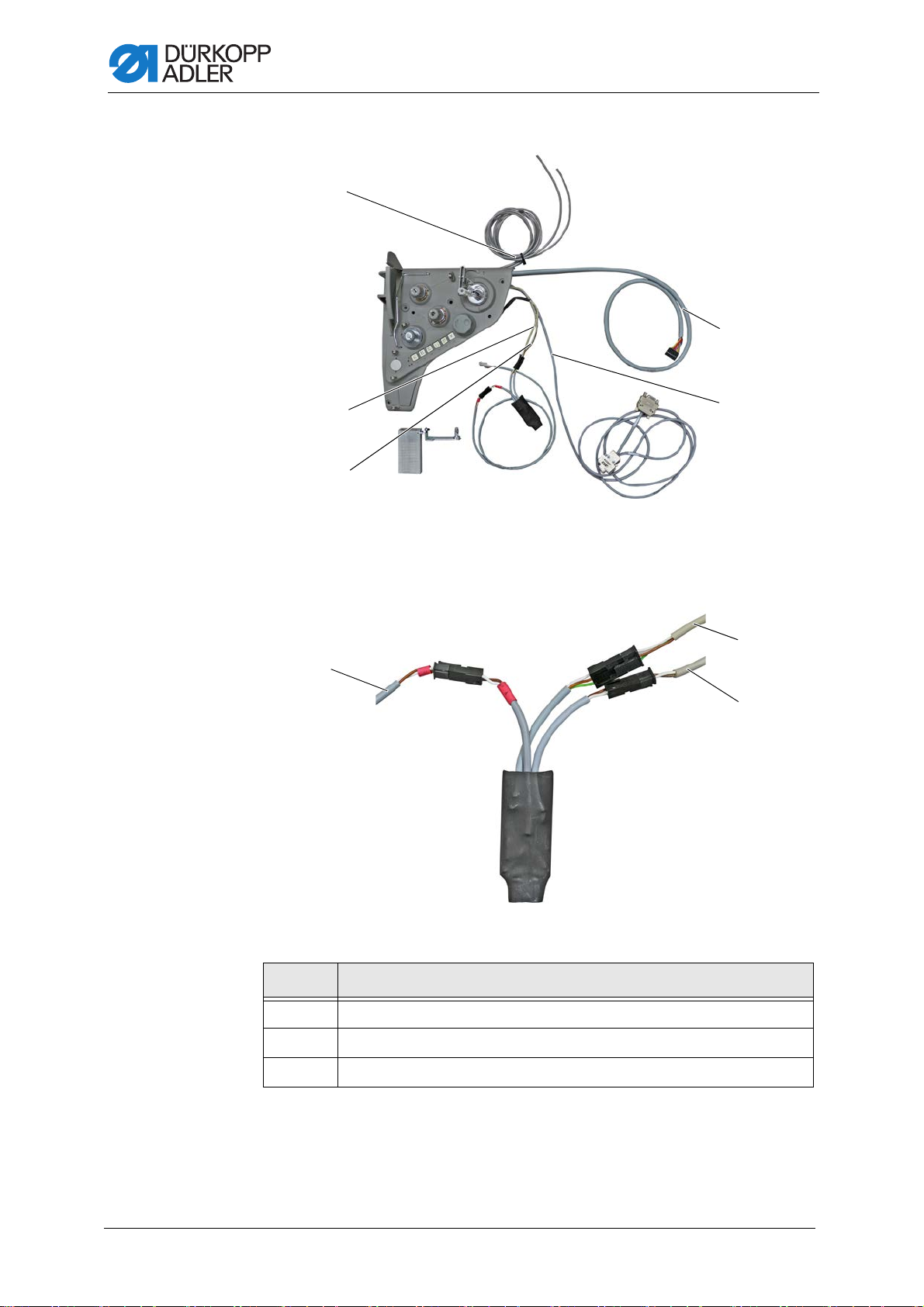
Fig. 2: Tensioning plate kit
①
②
③
④
⑤
⑧
⑦
⑥
General information
(1) - Pneumatic hoses
(2) - Cable motor current
(3) - Cable microswitch
Fig. 3: Control motor
Cables of the control:
(4) - Cable electronic handwheel
(5) - Cable push button panel
No. Description
⑥
⑦
⑧
Cable supply (labeled white, brown - red)
Cable microswitch (white, brown)
Cable motor current (green, white, brown)
4 Additional Instructions H-TYPE - 00.0 - 09/2017
Page 7

Disassembling the old tensioning plate
①②
2 Disassembling the old tensioning plate
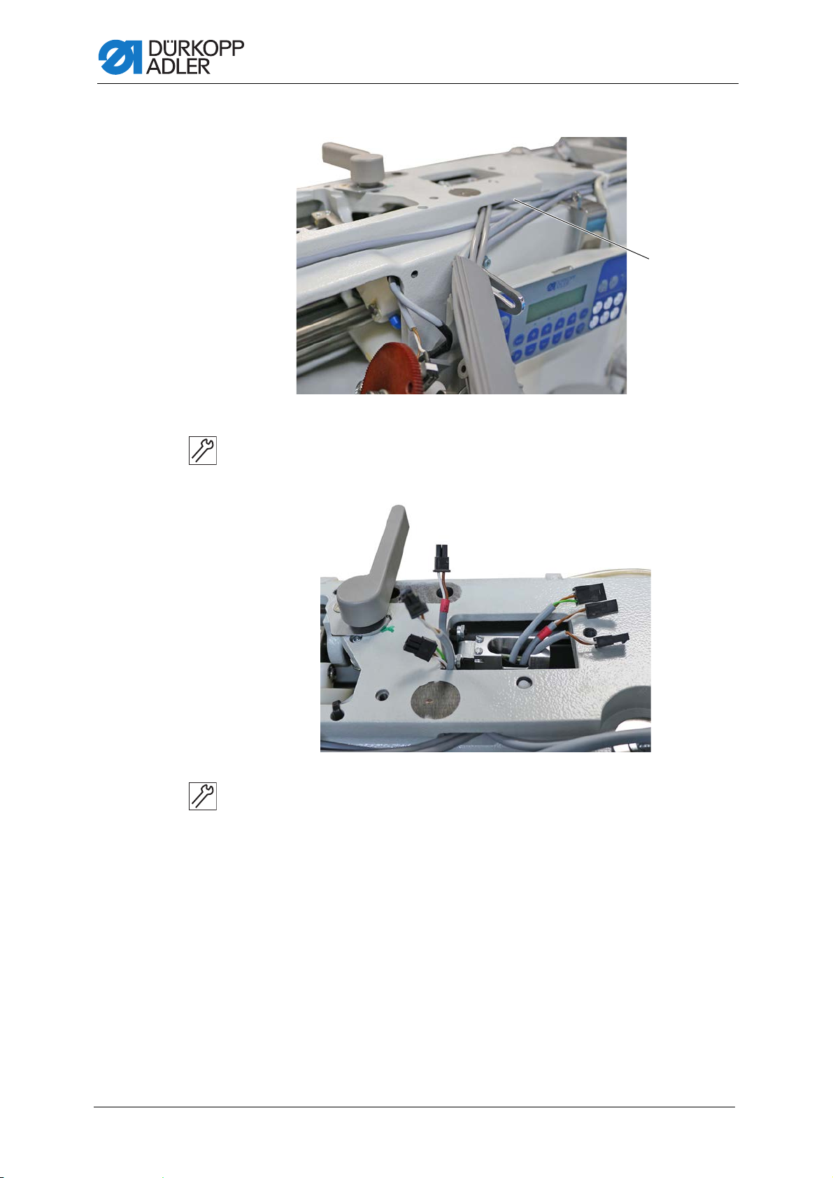
Fig. 4: Disassembling the old tensioning plate
WARNING
The tensioning plate may only be disassembled by
qualified specialists.
Switch off the machine and disconnect the power
plug before disassembling the tensioning plate.
Make sure the power plug cannot be
unintentionally reinserted.
(1) - Left arm cover (2) - Right arm cover
To disassemble the old tensioning plate:
1. Switch off the machine.
2. Loosen 5 screws on the left arm cover (1).
3. Remove the left arm cover (1).
4. Loosen 5 screws on the right arm cover (2).
5. Remove the right arm cover (2) while disconnecting the cable of the
lifter at the plug.
Additional Instructions H-TYPE - 00.0 - 09/2017 5
Page 8

Disassembling the old tensioning plate
⑥
⑤
③
④
⑦
⑧
⑧
Fig. 5: Disassembling the old tensioning plate
(3) - Screw
(4) - Belt cover
6. Loosen 3 screws (3) on the handwheel (6).
7. Remove the handwheel (6).
8. Loosen 4 screws (5) on the belt cover (4).
9. Remove the belt cover (4).
Fig. 6: Disassembling the old tensioning plate
(5) - Screw
(6) - Handwheel
(7) - Tensioning plate (8) - Screw
10. Loosen 5 screws (8) on the tensioning plate (7).
11. Pull the tensioning plate (7) sightly forward to remove it.
6 Additional Instructions H-TYPE - 00.0 - 09/2017
Page 9

Disassembling the old tensioning plate
⑨
⑩
⑪
⑫
⑦
Fig. 7: Disassembling the old tensioning plate
(7) - Tensioning plate
(9) - Cable motor current
(10) - Cable electronic handwheel
12. Attached to the tensioning plate (7) are 3 cables (9) (10) (11) and
2 pneumatic hoses (12).
13. Carefully loosen the cables and the hoses from their installed positions
inside the machine before detaching them from their slots.
14. Remove the old tensioning plate completely.
The tensioning plate has been disassembled.
(11) - Cable push button panel
(12) - Pneumatic hoses
Additional Instructions H-TYPE - 00.0 - 09/2017 7
Page 10

Assembling the new tensioning plate
①
②
3 Assembling the new tensioning plate
WARNING
The tensioning plate may only be assembled by
qualified specialists.
Switch off the machine and disconnect the power
plug before assembling the tensioning plate.
Make sure the power plug cannot be
unintentionally reinserted.
NOTICE
Property damage may occur!
The cables and hoses may become damaged by kinking, crushing
or chafing.
Lay cables and hoses in such a way that they will NOT be kinked,
pinched or chafed.
Fig. 8: Assembling the new tensioning plate
(1) - Holder (2) - Carrier
To assemble the new tensioning plate:
1. Unscrew the holder (1) from the carrier (2) of the control.
2. Insert the holder (1) from below into the hole (3) in the machine arm.
8 Additional Instructions H-TYPE - 00.0 - 09/2017
Page 11

Assembling the new tensioning plate
③
④
①
⑤
⑥
⑤
①
Fig. 9: Assembling the new tensioning plate
(1) - Holder
(3) - Hole
3. Tighten the screw (4) from above.
The screw (4) will clamp itself in place.
Fig. 10: Assembling the new tensioning plate
(1) - Holder
(5) - Counternut
4. Secure the holder (1) to prevent it from shifting using the adjusting
screws (6) and the counternuts (5).
(4) - Screw
(6) - Adjusting screw
Additional Instructions H-TYPE - 00.0 - 09/2017 9
Page 12

Fig. 11: Assembling the new tensioning plate
①
⑧
⑦
⑨
Assembling the new tensioning plate
(1) - Holder
(7) - Screw
5. Slip the carrier (8) of the control onto the holder (1) and tighten it using
the screws (7).
Fig. 12: Assembling the new tensioning plate
(9) - Control
6. Loosen the 3 plugs of the cables to disconnect them from the control (9).
(8) - Carrier
7. Place the control (9) into the previously assembled carrier (8).
10 Additional Instructions H-TYPE - 00.0 - 09/2017
Page 13

Assembling the new tensioning plate
⑪
⑭
⑬
⑫
⑩
⑮
⑬
⑫
Fig. 13: Assembling the new tensioning plate
(10) - Tensioning plate
(11) - Cable motor current
(12) - Cable microswitch
8. Lay the 4 cables (11) (12) (14) (15) and pneumatic hoses (13) of the
new tensioning plate (10) inside the machine as shown above.
9. Tighten the tensioning plate (10) using 5 screws.
Fig. 14: Assembling the new tensioning plate
(13) - Pneumatic hoses
(14) - Cable push button panel
(15) - Cable electronic handwheel
(11) - Cable motor current (12) - Cable microswitch
10. Lay cables (11) and (12) behind the tensioning plate (10) and under
the casting to the control (9).
Additional Instructions H-TYPE - 00.0 - 09/2017 11
Page 14
Assembling the new tensioning plate
⑯
Fig. 15: Assembling the new tensioning plate
(16) - Connecting cable
11. Slip the connecting cable (16) (marked in red) through the slot and
guide it to the control (9).
Fig. 16: Assembling the new tensioning plate
12. Use the plugs to connect the cables with the control:
white/brown - white/brown (marked in red)
white/brown - white/brown (2-prong plug)
green/white/brown - green/white/brown (3-prong plug)
13. Carefully push the plug down, preventing you from being pinched by
the arm cover.
14. Lay cables (14) and (15) and the pneumatic hoses (13) in the same
way as the old cables, avoiding any wear, crushing and shearing points.
12 Additional Instructions H-TYPE - 00.0 - 09/2017
Page 15

Assembling the new tensioning plate
⑰
⑬
Fig. 17: Assembling the new tensioning plate
(17) - Plug
15. Insert the plug (17) of the cable used for the electronic handwheel (15)
into the control.
Fig. 18: Assembling the new tensioning plate
(13) - Pneumatic hoses
16. Slip the pneumatic hoses (13) onto the valves.
Additional Instructions H-TYPE - 00.0 - 09/2017 13
Page 16

Fig. 19: Assembling the new tensioning plate
⑯
⑱
⑲
⑭
Assembling the new tensioning plate
(14) - Cable push button panel
(16) - Connecting cable
17. Use the black plug to insert the cable of the push button panel (14) into
the matching slot on the circuit board.
18. Use the white plug and the brown plug to connect the connecting
cable (16) that supplies power to the winder via the control to pin 8 (18)
and pin 10 (19), respectively, of the X22 terminal strip on the circuit
board.
19. Place the belt cover back on and fix it in place with 4 screws.
20. Assemble the handwheel and fix it in place with 3 screws.
21. Tighten the right arm cover with 5 screws while reconnecting the lifter.
22. Re-tighten the left arm cover using 5 screws.
23. Plug the power cable back in.
24. Switch on the machine.
The machine is ready for sewing.
(18) - Pin 8 (24V)
(19) - Pin 10 (0V)
14 Additional Instructions H-TYPE - 00.0 - 09/2017
Page 17

Page 18

DÜRKOPP ADLER AG
Potsdamer Str. 190
33719 Bielefeld
Germany
Phone: +49 (0) 521 925 00
Email: service@duerkopp-adler.com
www.duerkopp-adler.com
Subject to design changes - Part of the machines shown with additional equipment - Printed in Germany
© Dürkopp Adler AG - Additional Instructions - 0791 967701 EN - 00.0 - 09/2017
 Loading...