

Page 1

969
Service Instructions
Page 2

All rights reserved.
Property of Dürkopp Adler AG and protected by copyright. Any reuse of these contents,
cluding extracts, is prohibited without the prior written approval of Dürkopp Adler AG.
in
Copyright © Dürkopp Adler AG - 2015
Page 3

Table of Contents
1 About these Service Instructions..............................................3
1.1 Scope of the Service Instructions.................................................3
1.2 Representation conventions – symbols and characters...............3
1.3 Other documents..........................................................................4
1.4 Liability..........................................................................................4
2 Safety...........................................................................................5
2.1 Basic safety instructions...............................................................5
2.2 Signal words and symbols used in warnings................................6
3 Basic Principles of Working with the Machine........................9
3.1 Sequence of the settings..............................................................9
3.2 Cable routing................................................................................9
3.3 Removing the covers..................................................................10
3.3.1 Access to the underside of the machine.....................................10
3.3.2 Removing and fitting the arm cover............................................11
3.3.3 Removing and fitting the head cover..........................................12
3.3.4 Removing and fitting the cover plate..........................................12
3.3.5 Removing and fitting the handwheel and belt cover...................13
3.3.6 Removing and installing the thread tension plate.......................13
3.3.7 Removing and installing the hook compartment cover...............14
3.3.8 Removing and installing the throat plate .................................... 15
3.3.9 Removing and installing the feed dog ........................................ 16
3.4 Flats on shafts ............................................................................17
3.5 Axial play for shafts running in plain bearings............................18
3.6 Locking the machine in place.....................................................19
3.7 Moving the handwheel into position ........................................... 20
4 Positioning the arm shaft.........................................................21
5 Setting the handwheel scale ...................................................23
6 Setting the drive .......................................................................25
6.1 Setting the drive ratio..................................................................25
6.1.1 Removing the belt.......................................................................25
6.1.2 Adjusting the drive pulley............................................................26
6.1.3 Adjusting the belt tension ...........................................................27
6.2 Adjusting the positioning of the machine....................................28
6.2.1 Determining the drive ratio in the control program......................28
6.2.2 Adjusting the reference position of the handwheel.....................28
7 Setting the stitch length adjusting wheels............................. 31
7.1 Setting the upper stitch length adjusting wheel.......................... 31
7.2 Setting the lower stitch length adjusting wheel...........................33
7.3 Setting the stitch length limit.......................................................35
7.4 Setting the eccentric for the forward and backward stitches......37
8 Setting the feed dog.................................................................39
8.1 Setting the feed dog position......................................................39
8.1.1 Moving the feed dog...................................................................40
8.1.2 Moving the feed dog carrier........................................................40
8.2 Setting the feed dog movement..................................................42
8.2.1 Adjusting the forward movement................................................42
Service Instructions 969 - 01.0 - 12/2015
1
Page 4

Table of Contents
8.2.2 Setting the feed dog height at top dead center...........................43
8.2.3 Setting the stroke movement......................................................44
9 Aligning the needle bar linkage...............................................47
9.1 Moving the needle bar linkage sideways....................................47
9.2 Aligning the needle bar linkage in the sewing direction..............49
10 Position of the hook and needle .............................................51
10.1 Tensioning the hook drive toothed belt.......................................51
10.2 Adjusting the dead center of the reciprocating movement of
the driver.....................................................................................52
10.3 Setting the loop stroke position .................................................. 53
10.4 Setting the hook clearance.........................................................54
10.5 Adjusting the loop former............................................................55
10.6 Setting the needle bar height......................................................56
11 Adjusting the sewing foot feed ...............................................59
11.1 Adjusting the zero stroke of the feet, tension force of the
torsion spring..............................................................................59
11.2 Adjusting the drive dog for the presser foot bar..........................60
11.3 Aligning the feed stroke of the feet.............................................61
11.4 Setting the stroke movement for the feeding foot.......................62
12 Adjusting the foot stroke.........................................................65
12.1 Adjusting the foot stroke using the hand lever............................65
12.2 Adjusting the foot stroke using the pneumatic cylinder...............66
13 Adjusting the thread system ...................................................67
13.1 Setting the thread tensioning spring........................................... 67
13.2 Setting the winder.......................................................................68
13.3 Setting the hook thread guide.....................................................72
14 Adjusting the thread cutter...................................................... 75
14.1 Adjusting the thread cut-off point................................................75
14.2 Basic setting of the thread cutter................................................76
14.3 Adjusting the position of the movable knife................................ 77
14.4 Adjusting the cutting pressure of the knife..................................78
15 Soft start....................................................................................81
16 Maintenance..............................................................................83
16.1 Cleaning the filter element..........................................................83
16.2 Lubricating the needle bar..........................................................85
2
Service Instructions 969 - 01.0 - 12/2015
Page 5

About these Service Instructions
1.
2.
etc.
•
1 About these Service Instructions
These instructions for sewing machine 969 have been compiled with the
utmost care. They contain information and notes intended to ensure longterm and reliable operation.
1.1 Scope of the Service Instructions
These instructions describe the setting and maintenance work on the
969 machine. They apply to all submodels.
The intended use and setup is described in the Ope
1.2 Representation conventions – symbols and characters
Various information in these instructions is represented or highlighted by the
following characters in order to facilitate easy and quick understanding:
Proper setting
Indicates proper setting.
rating Instructions.
Malfunctions
Specifies the faults that can occur due to an incorrect setting.
Steps to be performed when operating the machine (sewing and
e
quipping)
Steps to be performed for service, maintenance, and installation
Steps to be performed via the software control panel
The individual steps are numbered:
1. First step
2. Second step
The steps must always be followed in the specified order.
Lists are marked by bullet points.
Result of performing an operation
Change to the machine or display.
Important
Special attention must be paid to this point when performing a step.
Service Instructions 969 - 01.0 - 05/2015
3
Page 6

About these Service Instructions
Information
Additional information, e.g. on alternative operating options.
Sequence
Specifies the work to be performed before or after a setting.
References
Reference to another section in these instructions.
Safety Important warnings for the machine users are specially designated. Since
safety is of particular importance, hazard symbols, levels of danger and
their signal words are described separately in section 2 Safety.
Orientation If no other clear location markers are used in a diagram, indications of right
or left are always from the operator's point of view.
1.3 Other documents
Some of the machine's built-in components have been made by third-party
manufacturers. Each manufacturer has performed a hazard assessment
for these purchased parts and confirmed their design compliance with applicable European and national regulations. The proper use of these components is described in each manufacturer's instructions.
1.4 Liability
All information in these service instructions was compiled in accordance
with the current state of the art and the applicable standards and
regulations.
Dürkopp Adler cannot be held liable for damages resulting from:
• Breakage and damage during transport
• Failure to follow the operating instructions
• Improper use
• Unauthorized modifications to the machine
• Use of untrained personnel
• Use of unapproved replacement parts
4
Service Instructions 969 - 01.0 - 05/2015
Page 7

Safety
2 Safety
This chapter contains basic information for your safety. Read the instructions carefully before setting up or operating the machine. Always follow
t
he information included in this section. Failure to do so can result in seri-
ous injury and property damage.
2.1 Basic safety instructions
The machine may only be used as described in these instructions.
The instructions should be available at th
Work on live components and equipment is prohibited
e machine's location at all times.
. Exceptions are de-
fined in the DIN VDE 0105.
For the following work, the machine must be disconnected from the power
ly using the main switch or by disconnecting the power plug:
supp
• Replacing the needle or other sewing tools
• Leaving the workstation
• Performing maintenance work and repairs
• Threading
Missing or faulty spare parts could impair safety and damage the machine.
Make sure
Transport Use a sturdy lifting carriage or forklift truck for transporting the machine.
you only use original replacement parts from the manufacturer.
Raise the machine max. 20 mm and secure it to prevent it from slipping
ff.
o
Setup The power cable must have a plug that is authorized for use in the country
in which the machine is being used. The power plug may only be connected to the power cable by qualified specialists.
Obligations
of the operator
Observe the country-specific safety and accident prevention regulations
and the legal regulations concerning industrial safety and the protection of
the environment.
All the warnings and safety signs on the machine must always be in legible
ition, and must not be removed. Missing or damaged labels must be
cond
replaced immediately.
Requirements
to be met by
the personnel
The machine may only be set up by qualified specialists.
Maintenance work and repairs may only be carried out by qualified
pecialists.
s
Work on electrical equipment may only be carried out by qualified
pecialists.
s
Only authorized persons may work on the machine. Every person who
works o
Service Instructions 969 - 01.0 - 12/2015 5
n the machine must first have understood these instructions.
Page 8

Safety
Operation Inspect the machine for any externally visible damage during use. Stop
working if you notice any changes to the machine. Report any changes to
your supervisor. Machines must no longer be used if they are damaged.
Safety
equipment
Safety equipment should not be removed or deactivated. If it is essential
to remove or deactivate safety equipment for a repair operation, it must be
refitted and put back into service immediately afterward.
2.2 Signal words and symbols used in warnings
Warnings in the text are distinguished by color bars. The color scheme
based on the severity of the danger. Signal words indicate the severity of
the danger.
Signal words Signal words and the hazard that they describe:
Signal word Meaning
DANGER (with hazard symbol)
If ignored, fatal or serious injury will result
WARNING (with hazard symbol)
If ignored, fatal or serious injury can result
CAUTION (with hazard symbol)
If ignored, moderate or light injury can result
NOTICE (without hazard symbol)
If ignored, property damage can result
Symbols The following symbols indicate the type of danger to personnel:
Symbol Type of danger
General
Electric shock
Puncturing
Crushing
Environmental damage
6 Service Instructions 969 - 01.0 - 12/2015
Page 9

Safety
Examples Examples of the layout of warnings in the text:
DANGER
Type and source of danger!
Consequences of non-compliance.
Measures for avoiding the danger.
This is what a warnin
injury or even death if ignored.
g looks like for a hazard that will result in serious
WARNING
Type and source of danger!
Consequences of non-compliance.
Measures for avoiding the danger.
This is wh
ous or even fatal injury if ignored.
at a warning looks like for a hazard that could result in seri-
CAUTION
Type and source of danger!
Consequences of non-compliance.
Measures for avoiding the danger.
This is what a warn
moderate or minor injury if the warning is ignored.
ing looks like for a hazard that could result in
CAUTION
Type and source of danger!
Consequences of non-compliance.
Measures for avoiding the danger.
This is what
environmental damage if ignored.
Service Instructions 969 - 01.0 - 12/2015 7
a warning note looks like for a hazard that could result in
Page 10

Safety
NOTICE
Type and source of danger!
Consequences of non-compliance.
Measures for avoiding the danger.
This is what a warning looks like for a hazard that could result in
property damage if ignored.
8 Service Instructions 969 - 01.0 - 12/2015
Page 11

Basic Principles of Working with the Machine
3 Basic Principles of Working with the Machine
3.1 Sequence of the settings
The setting positions for the machine are interdependent.
Always adhere to the specified sequence for the individual setting steps.
Always observe all the information on requirements and following settings
marked at the side with .
NOTICE
Risk of machine damage due to incorrect sequence.
Always adhere to the working se
instructions.
quence specified in these
3.2 Cable routing
Ensure that all cables in the machine are laid in such a way that they do
not impair the function of the moving parts.
1. Lay any excess cabling neatly in
2. Tie the snakes together using a cable tie.
If possible, bind the snakes to fixed parts.
The cables must be fixed firmly in place.
3. Cut any excess material off the cable tie.
proper cable snakes.
NOTICE
Machine damage and malfunctions can be caused by laying
the cables incorrectly.
Excess cabling may prevent moving ma
correctly. This will affect the sewing operation, and may cause
damage.
Lay excess cabling as described above.
chine parts from functioning
Service Instructions 969 - 01.0 - 12/2015
9
Page 12

Basic Principles of Working with the Machine
①
3.3 Removing the covers
WARNING
Risk of injury!
Crushing injuries from moving parts.
Switch the machine off before you remove the
cove
rs or refit them.
For many types of setting work, you will have to remove the machine covers in order to access the components.
This section describes how to remove the
The text for each type of setting work then specifies only the cover that
needs to be removed at that particular time.
individual covers and refit them.
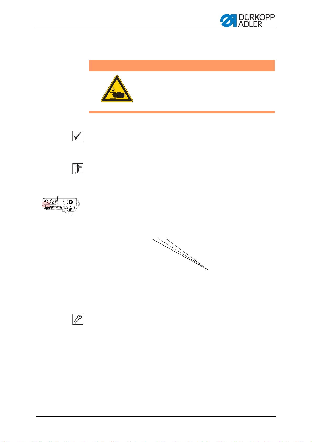
3.3.1 Access to the underside of the machine
In order to access the components on the underside of the machine, you
must first swivel up the machine head.
Fig. 1: Tilting and erecting the machine head
Tilting the machine head
1. Push the lever (1) up.
Th
e locking mechanism disengages.
2. Tilt the machine head.
10
Erecting the machine head
1. Tilt the machine head forward.
2
. Pull the lever (1) up again and carefully tilt the machine head back down.
Service Instructions 969 - 01.0 - 12/2015
Page 13
Basic Principles of Working with the Machine
(1) - Right adjusting wheel
(2) - Left adjusting wheel
(3) - Screws
(4) - Upper left cover
(5) - Upper right cover
(6) - Screws
(7) - Lever
①
②
③
④
⑤
⑥
⑦
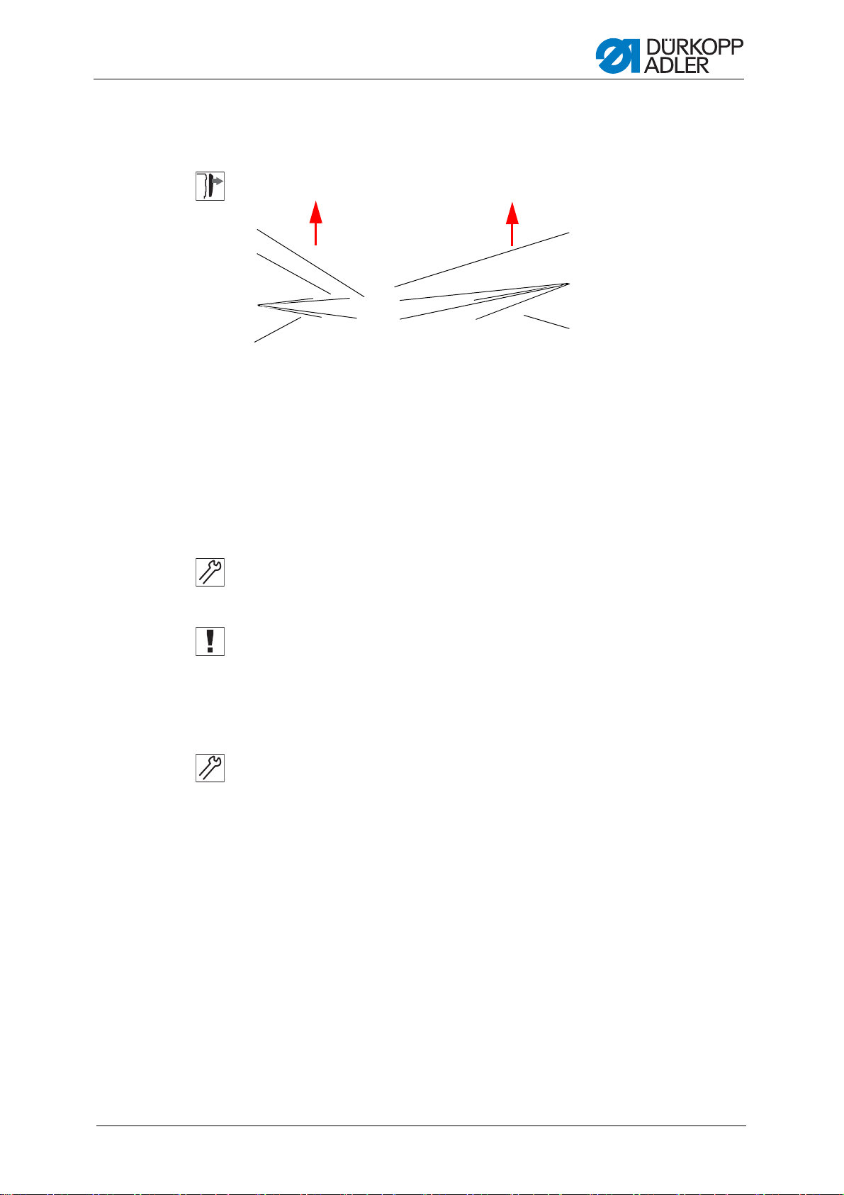
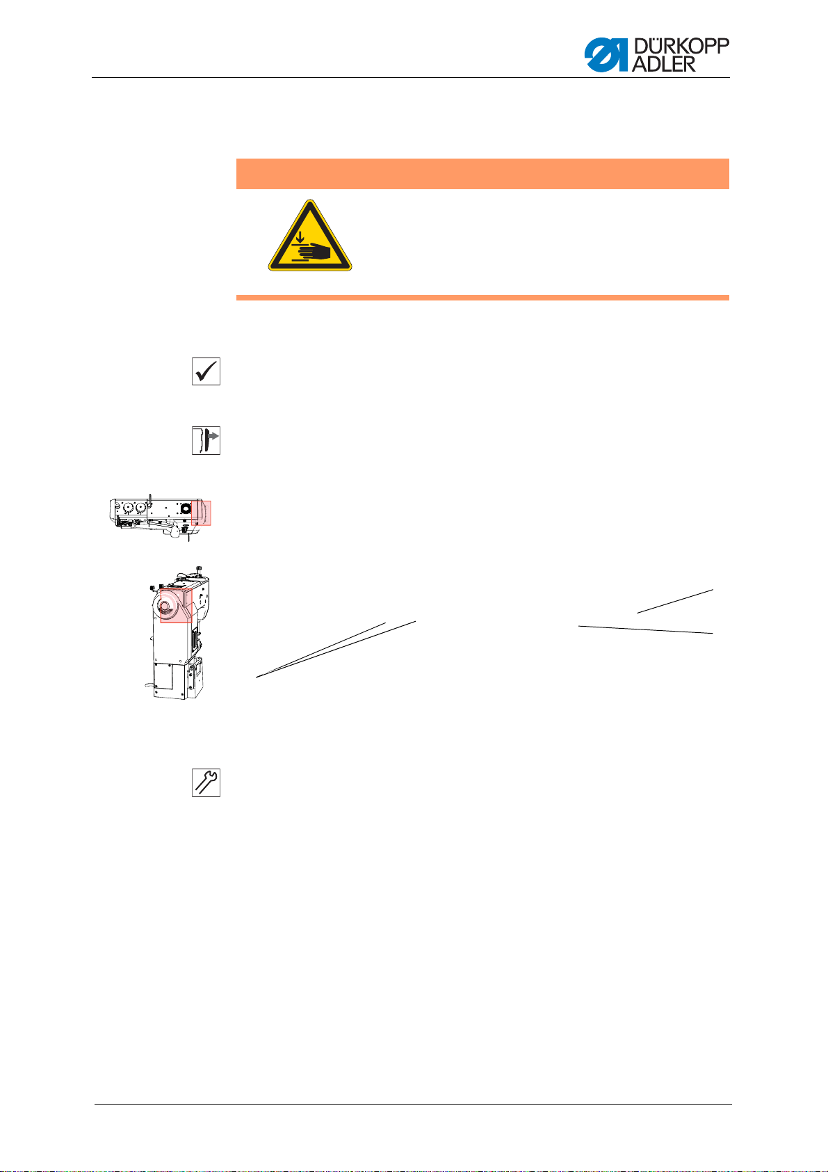
3.3.2 Removing and fitting the arm cover
If necessary, each of the two top covers can be removed separately.
Fig. 2: Removing and fitting the arm cover
Removing the left arm cover
1. Turn left adjusting wheel (2) to position 0.
2
. Turn right adjusting wheel (1) to position 8.
The cover cannot be removed unless the adjusting wheels are set to
the proper position.
3. Loosen the screws (3).
4. Lift the upper left cover (4) up in the direction of the arrow.
Removing the right arm cover
1. Turn the lever (7) clockwise as far as it will go.
2
. Loosen the screws (6).
3. Raise the cover and disconnect the power plug for the fan that is attached
to the underside of the cover.
4. Lift the upper right cover (5) up in the direction of the arrow.
Service Instructions 969 - 01.0 - 12/2015
11
Page 14

Basic Principles of Working with the Machine
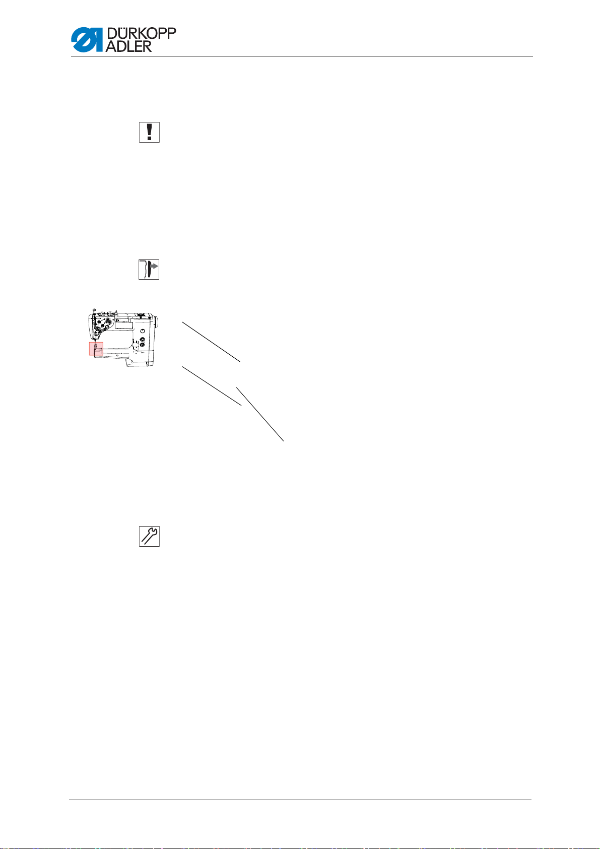
(1) - Head cover (2) - Screws
①
②
(1) - Cover plate (2) - Screws
①
②
3.3.3 Removing and fitting the head cover
Fig. 3: Removing the head cover
Removing the head cover
1. Loosen the screws (2).
2. Remove the head cover (1).
3.3.4 Removing and fitting the cover plate
Fig. 4: Removing the cover plate
Removing the cover plate
12
1. Loosen the screws (2).
2
. Remove the cover plate (1).
Service Instructions 969 - 01.0 - 12/2015
Page 15

Basic Principles of Working with the Machine
(1) - Handwheel fastening screws
(2) - Handwheel
(3) - Belt cover
(4) - Belt cover fastening screws
①
③
④
(1) - Upper right cover
(2) - Thread tension plate fastening
screws
(3) - Thread tension plate
①
③
3.3.5 Removing and fitting the handwheel and belt cover
Fig. 5: Removing the belt cover
Removing the belt cover
1. Loosen the screws (1).
2
. Remove the handwheel (2).
3. Loosen the screws (4).
4. Take off the belt cover (3).
3.3.6 Removing and installing the thread tension plate
Fig. 6: Removing the thread tension plate
Service Instructions 969 - 01.0 - 12/2015
13
Page 16
Basic Principles of Working with the Machine
(1) - Cover (2) - Screw
③
Removing the thread tension plate
1. Start by removing the upper right cover (1).
As the th
read tension plate is connected to cables and hoses that are
attached below the upper right cover, you will need to remove this cover first.
2. Loosen the screws (2).
3. Take off the thread tension plate (3).
3.3.7 Removing and installing the hook compartment cover
Fig. 7: Removing the hook compartment cover
Removing the hook compartment cover
1. Push in the cover (1) at position (3).
2
. Turn the cover (1) clockwise.
3. Loosen the screw (2).
4. Remove the cover (1).
14
Service Instructions 969 - 01.0 - 12/2015
Page 17

Basic Principles of Working with the Machine
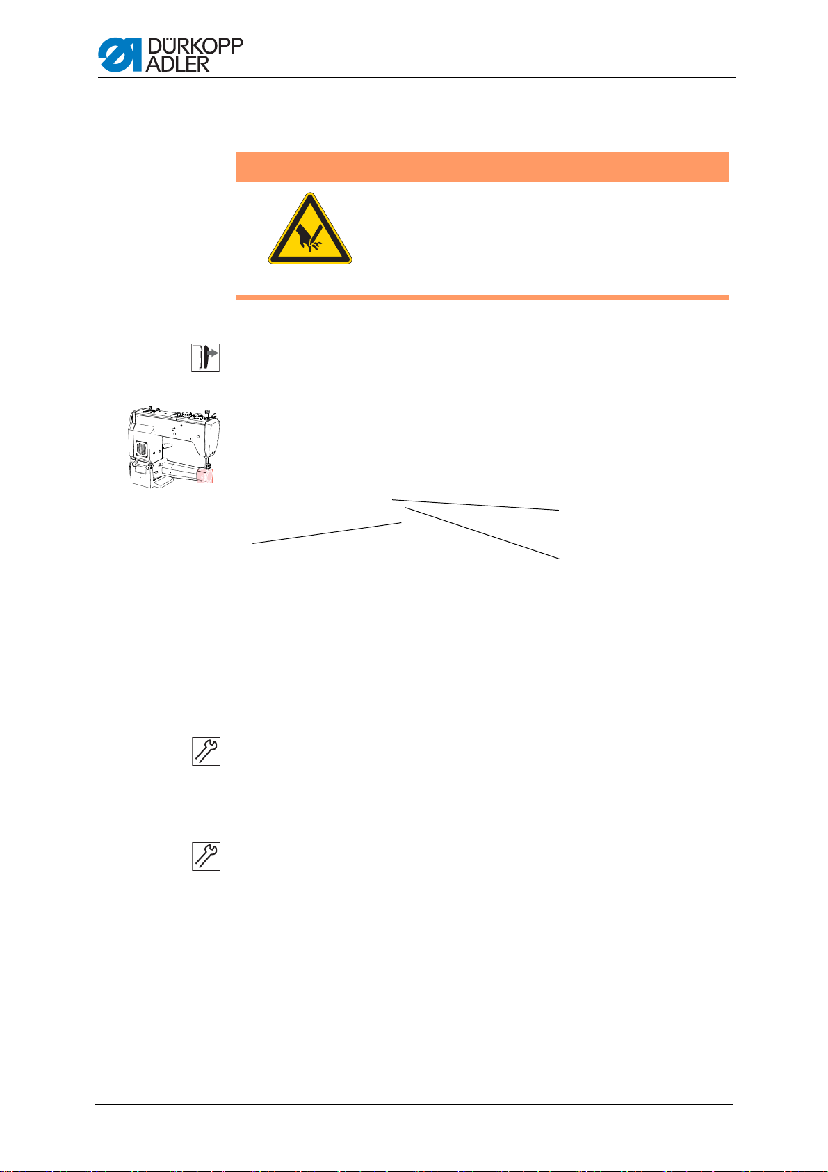
(1) - Throat plate (2) - Screws
①
②
3.3.8 Removing and installing the throat plate
WARNING
Risk of injury!
Risk of crushing injuries and stab wounds from
sharp
Switch the machine off before you remove or install
th
Fig. 8: Removing and installing the throat plate
and moving parts.
e throat plate.
Removing the throat plate
1. Raise the sewing feet.
2
. Loosen the screw (2).
3. Remove the throat plate (1).
Service Instructions 969 - 01.0 - 12/2015
15
Page 18
Basic Principles of Working with the Machine
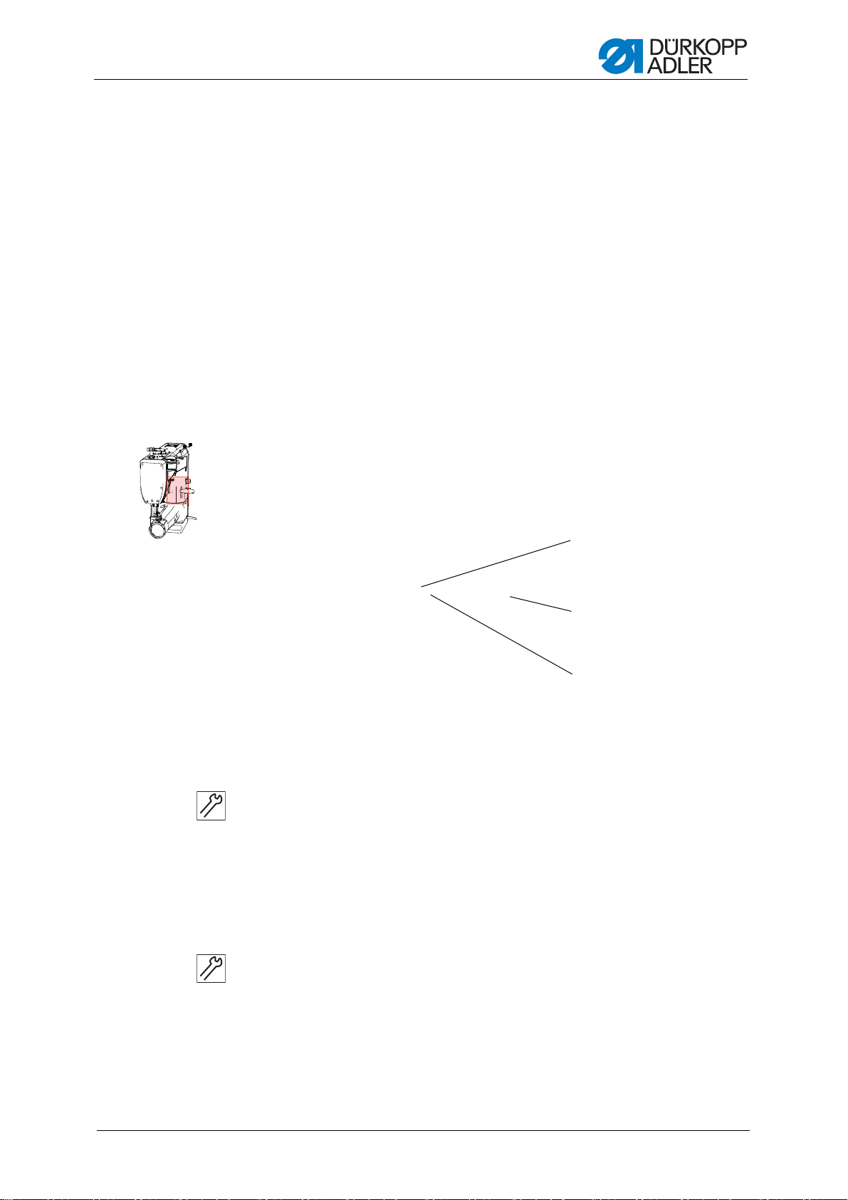
(1) - Feed dog carrier
(2) - Screws
(3) - Feed dog
②
③
3.3.9 Removing and installing the feed dog
WARNING
Risk of injury!
Risk of crushing injuries and stab wounds from
sharp
Switch the machine off before you remove or install
th
Fig. 9: Removing and installing the feed dog
and moving parts.
e feed dog.
16
Removing the feed dog
1. Remove the throat plate ( p
. 15).
2. Loosen the screws (2).
3. Take the feed dog (3) off the feed dog carrier (1).
Installing the feed dog
1. Place the feed dog (3) on the feed dog carrier (1) and lightly tighten the
screws (2).
2
. Install the throat plate ( p. 15)
3. Adjust the feed dog (3) so that it has an equal amount of play on both
sides when inside the throat plate.
4. Tighten the screws (2).
Service Instructions 969 - 01.0 - 12/2015
Page 19

Basic Principles of Working with the Machine
(1) - Shaft (2) - Surface
①
3.4 Flats on shafts
Fig. 10: Flats on shafts
Some shafts have flat surfaces at the points where the components are
screwed on. This stabilizes the connection and makes adjustment easier.
Always ensure that the screw faces are completely flush with the surface.
Service Instructions 969 - 01.0 - 12/2015
17
Page 20

Basic Principles of Working with the Machine
(1) - Plain bearing shell
(2) - Shaft
(3) - Lever
(4) - Adjusting ring
④
3.5 Axial play for shafts running in plain bearings
Fig. 11: Axial play for shafts running in plain bearings
Shafts (2) running in plain bearing shells (1) are axially adjusted when the
lever (3) and the adjusting ring (4) touch the front face of the bearing
shells (1).
When adjusting components mounted on shafts running in plain bearings,
always ensure that the axial play of these shafts is as small as possible,
or 0.
18
Service Instructions 969 - 01.0 - 12/2015
Page 21
Basic Principles of Working with the Machine
(1) - Slot
(2) - Arresting pin
(3) - Locking opening
①
②
③
3.6 Locking the machine in place
For some settings, the machine has to be locked in place. To do this, the
arresting pin from the accessory pack is inserted into a slot on the arm
shaft crank, blocking the arm shaft.
There are 2 securing positions:
• Posi
• Posi
Fig. 12: Locking the machine in place
tion 1: Loop stroke position
• 5 mm end in the large slot
•
Setting the loop stroke and needle bar height
tion 2: Handwheel zero position
• 3 mm end in the small slot
•
Setting the handwheel position and checking the bottom dead cen-
ter for the needle bar
Locking the machine in place
1. Turn the handwheel until t he appropriate slot (1) is in front of the locking
op
ening (3):
• Small slot at handwheel position 180°
• Large slot at handwheel position 200 – 205°
2. Insert the corresponding end of the arresting pin (2) into the slot (1).
Removing the positional lock
1. Pull the arresting pin (2) out of the slot (1).
Service Instructions 969 - 01.0 - 12/2015
19
Page 22

Basic Principles of Working with the Machine
①
②
(1) - Graduated scale (2) - Marking
3.7 Moving the handwheel into position
For some settings, the graduated scale on the handwheel has to be
moved to a certain position.
Fig. 13: Moving the handwheel into position
Setting steps
1. Turn the handwheel until the specified number on the graduated
scale
(1) is next to the marking (2).
20
Service Instructions 969 - 01.0 - 12/2015
Page 23
Positioning the arm shaft
(1) - Setscrews
①
4 Positioning the arm shaf t
Proper setting
The 3 setscrews (1) are seated flush on
flush with the machine casting.
Cover
• Upper left cover, ( p. 11).
WARNING
Risk of injury!
Crushing injuries from moving parts.
Switch the machine off before you check and set
th
e position of the arm shaft crank.
the flat. The arm shaft crank is
Fig. 14: Setting the arm shaft crank
Setting steps
1. Loosen all the setscrews (1) on the arm shaft crank.
2
. Turn the arm shaft crank so that the setscrews (1) are seated flush on
the flat of the arm shaft.
3. Push the arm shaft to the right as far as it will go, un til it is flush with the
machine casting.
4. Tighten all the setscrews (1) on the arm shaft crank.
Service Instructions 969 - 01.0 - 12/2015
21
Page 24

Positioning the arm shaft
22
Service Instructions 969 - 01.0 - 12/2015
Page 25
Setting the handwheel scale
(1) - Screws
(2) - Handwheel
(3) - Opening for the hex key
①
②
③
5 Setting the handwheel scale
Proper setting
Lock the machine in place at position 2 ( p. 19).
Th
e handwheel is at the 180° position.
Cover
• Remove handwheel and belt cover ( p. 13).
Fig. 15: Setting the handwheel scale
WARNING
Risk of injury!
Crushing injuries from moving parts.
Switch the machine off before you check and set
th
e position of the handwheel on the arm shaft.
Setting steps
1. Remove the belt cover and handwheel (
drive belt ( p. 25).
2. Loosen the screws (1).
3. Install the belt cover and handwheel.
4. Lock the machine in place at position 2 ( p. 19).
5. Set the handwheel (2) to 180° position ( p. 20).
6. Slide the hex key through the opening (3) and into the adjusting screw,
then tighten the screw.
7. Remove the belt cover and handwheel ( p. 13).
8. Tighten the screws (1).
9. Install the ridged drive belt together with the belt cover and handwheel.
Service Instructions 969 - 01.0 - 12/2015
p. 13), and take off the ridged
23
Page 26

Setting the handwheel scale
24
Service Instructions 969 - 01.0 - 12/2015
Page 27

Setting the drive
(1) - Ridged drive belt
(2) - Tensioning roller
(3) - Belt tensioner
(4) - Belt tensioner screws
①
②
③
④
6 Setting the drive
6.1 Setting the drive ratio
WARNING
Risk of injury!
Crushing injuries from moving parts.
Switch off the machine before checking and setting
th
e drive transmission ratio.
The machine is equipped with a 2-step pulley, which can be used to adjust
the drive ratio between the drive motor and the machine, and increase the
penetration force of the needle.
In order to change the ratio, the drive belt must be removed and the pulley
chan
ged to the opposite position. The drive belt is then refitted and
tensioned.
Cover
•Belt cover ( p. 13).
• Handwheel
6.1.1 Removing the belt
Fig. 16: Removing the belt
Service Instructions 969 - 01.0 - 12/2015
Setting steps
1. Loosen the screws (4) on the belt tensioner (3).
2
. Rotate the tensioning roller (2) and belt tensioner (3).
25
Page 28

Setting the drive
(1) - Driven pulley
(2) - Drive pulley
(3) - Adjusting screws
②
16 mm
16 mm
3. Take off the ridged drive belt (1).
6.1.2 Adjusting the drive pulley
WARNING
Risk of injury!
Crushing injuries from moving parts.
Switch off the machine before checking and setting
e drive pulley.
th
Proper setting
Regardless of which side of the drive pulley (2) is being used, there is a
ifference in height of 16 mm between the faces of the two pulleys.
d
Fig. 17: Adjusting the drive pulley
26
Setting steps
1. Loosen the screws (3).
2
. Pull the drive pulley (2) off the motor shaft and put it back on the other
way round.
3. Set a height difference of 16 mm between the faces of the drive pulley (2)
and the driven pulley (1).
4. Tighten the screws (3).
Service Instructions 969 - 01.0 - 12/2015
Page 29

Setting the drive
(1) - Checking point
(2) - Hexagonal opening
(3) - Belt tensioner
(4) - Screws
(5) - Drive pulley
(6) - Tensioning roller
(7) - Ridged drive belt
⑦
③
④
⑤
⑥
②
6.1.3 Adjusting the belt tension
WARNING
Risk of injury!
Crushing injuries from moving parts.
Turn off the machine before adjusting the belt
te
nsion.
Proper setting
The belt must be tight enough to not deflect by more than approx. 2 mm if
ressure is exerted at point 1.
p
Fig. 18: Adjusting the belt tension
Service Instructions 969 - 01.0 - 12/2015
Setting steps
1. Insert the ridged drive belt (7).
. Turn the tensioning roller (6) with the belt tensioner (3) against the ridged
2
drive belt (7).
3. Insert the hex key into the hexagonal opening (2), tension the ridged
drive belt (7) and tighten the screws (4).
4. Check the belt tension.
5. Correct the tension of the belt if necessary.
27
Page 30

Setting the drive
(1) - OP1000 control panel (2) - Handwheel
①
②
6.2 Adjusting the positioning of the machine
The machine will stop automatically at two angular positions on the main
shaft (of the handwheel). To ensure that the machine stops properly at
these positions, you need to set the reference position for the handwheel.
In order to ensure that the reference position is set p roperly, the drive ratio
b
etween motor and main shaft must be entered correctly into the control
program of the machine.
Fig. 19: Adjusting the positioning of the machine
6.2.1 Determining the drive ratio in the control program
Setting steps
1. Select parameter setting mode on the OP1000 control panel (1) and set
th
e parameter t 08 19 ( DAC basic/classic Service Instructions).
2. Manually rotate the handwheel (2) by at least 2 turns.
The display on the control panel will show a new value for the drive
ratio.
3. Press the OK key to confirm this new parameter value.
6.2.2 Adjusting the reference position of the handwheel
Proper setting
The reference position is at 105° on the handwheel scale (2).
Setting steps
1. Select parameter setting mode on the OP1000 control panel (1) and set
the parameter t 08 10 ( DAC basic/classic Service Instructions).
2. Manually rotate the handwheel (2) by at least one turn before turning it
to 105° on the scale ( p. 20).
28
Service Instructions 969 - 01.0 - 12/2015
Page 31

Setting the drive
3. Press the OK key to confirm the set position.
4. Press the Esc key to exit parameter setting mode.
5. Switch the machine on and off.
Service Instructions 969 - 01.0 - 12/2015
29
Page 32

Setting the drive
30
Service Instructions 969 - 01.0 - 12/2015
Page 33

Setting the stitch length adjusting wheels
(1) - Key for the stitch length
on the machine arm
(2) - Lower stitch length adjusting wheel
(3) - Upper stitch length adjusting wheel
①
②
③
7 Setting the stitch length adjusting wheels
Fig. 20: Stitch length adjusting wheels
The 2 adjusting wheels on the machine column determine the stitch
length.
• Upper adjusting wheel: large stitch length
• Lower adjusting wheel: small stitch length
It is not possible to set a larger stitch length on the lower adjusting wheel
han on the upper adjusting wheel.
t
To switch over between the stitch lengths: Press the key for the stitch
lengt
h on the machine arm (1).
If the upper adjusting wheel is activated, then the key (1) lights up.
When the machine is switched on, the most recently activated stitch length
a
djusting wheel is always active.
Sequence
Set the upper stitch length adjusting wheel first, then the lower stitch
lengt
h adjusting wheel.
7.1 Setting the upper stitch length adjusting wheel
WARNING
Risk of injury!
Crushing injuries from moving parts.
Switch the machine off before you set the upper
stitch le
ngth adjusting wheel.
Proper setting
Upper stitch length adjusting wheel to 0:
Service Instructions 969 - 01.0 - 12/2015
31
Page 34

Setting the stitch length adjusting wheels
(1) - Upper stitch length adjusting wheel
(2) - Screw
(3) - Lower stitch length adjusting wheel
(4) - Adjusting mark
(5) - Shaft
(6) - Scale
(7) - Wrench
②
①
④
③
⑤
⑥
⑦
No play on the stitch regulator gear. The plates for the gear are paral-
lel; the frame cannot be moved.
Cover
• Tilt the machine head ( p. 10)
Setting steps
1. Switch off the machine at the main switch.
The machine switches over to the uppe
Fig. 21: Setting the upper stitch length adjusting wheel I
r stitch length adjusting wheel.
2. Hold the upper stitch length adjusting wheel (1) in place using a
wrench (7).
3. Loosen the screw (2).
4. Remove the upper stitch length adjusting wheel (1) from the shaft (5).
NOTICE
Risk of machine damage if the shaft is turned too hard.
If you turn the shaft too far, parts on the stitch regulator gear may
bend o
r get stuck.
Turn the shaft carefully and stop as soon as you feel a slight
resistance.
5. Carefully turn the shaft (5) clockwise using a 10 mm wrench.
32
Service Instructions 969 - 01.0 - 12/2015
Page 35

Setting the stitch length adjusting wheels
(7) - Frame for the stitch regulator gear
⑧
Risk of injury!
The lower stitch length adjusting wheel has to be
set when the machine is switched on, as the machine automatically switches to the upper adjusting
wheel when it is switched off.
Carry out all work with extreme caution.
WARNING
Fig. 22: Setting the upper stitch length adjusting wheel II
6. Check whether the frame (8) for the stitch regulator gear can be moved
by pressing the stitch setting lever.
7. As soon as the frame (8) stops moving: Remove the wrench from the
shaft (5).
8. Turn the scale (6) so that the 0 is exactly next to the adjusting mark (4).
9. Place the upper stitch length adjusting wheel (1) onto the shaft (5) and
tighten it with a wrench (7).
10.Tighten the upper stitch length adjusting wheel (1) using screw (2).
Service Instructions 969 - 01.0 - 12/2015
7.2 Setting the lower stitch length adjusting wheel
Checking the correct setting
Sewing with 2 different stitch lengths:
• The stitch lengths on the seam correspond with the set stitch lengths.
• The lower stitch length adjusting wheel can only be turned up to the
stitch length
Cover
• Tilt the machine head ( p. 10)
set on the upper stitch length adjusting wheel.
33
Page 36

Setting the stitch length adjusting wheels
(1) - Key for the stitch length
on the machine arm
(2) - Lower stitch length adjusting wheel
(3) - Upper stitch length adjusting wheel
①
③
②
(1) - Upper stitch length adjusting wheel
(2) - Screw
(3) - Lower stitch length adjusting wheel
(4) - Adjusting mark
(5) - Shaft
(6) - Scale
(7) - Wrench
②
①
④
③
⑤
⑥
⑦
Fig. 23: Setting the lower stitch length adjusting wheel I
Setting steps
1. Position the upper stitch length adjusting wheel (3) > 3.
2
. Switch the machine to short stitch length.
The key for the stitch length (1) does not light up.
If the key lights up, press key (1) again.
Fig. 24: Setting the lower stitch length adjusting wheel II
3. Hold the lower stitch length adjusting wheel (3) in place using the
wrench (7).
4. Loosen the screw (2).
5. Remove the lower stitch length adjusting wheel (3) from the shaft (5).
34
NOTICE
Risk of machine damage if the shaft is turned too hard.
If you turn the shaft too far, parts on the stitch regulator gear may
bend o
r get stuck.
Turn the shaft carefully and stop as soon as you feel a slight
resistance.
Service Instructions 969 - 01.0 - 12/2015
Page 37

Setting the stitch length adjusting wheels
Risk of injury!
Crushing injuries from moving parts.
Switch off the machine before setting the maximum
stitch length limit.
WARNING
6. Carefully turn shaft (5) clockwise with a size 10 wrench until you feel
significant play on the frame for the stitch regulator gear.
7. Carefully turn shaft (5) counterclockwise with a size 10 wrench until you
no longer feel any play.
8. As soon as the frame stops moving: Remove the wrench from the
shaft (5).
9. Turn the scale (6) so that the 0 is exactly next to the adjusting mark (4).
10.Place the lower stitch length adjusting wheel (3) onto the shaft (5) and
tighten it with a wrench (7).
11.Tighten the lower stitch length adjusting wheel (3) using screw (2).
7.3 Setting the stitch length limit
If not all of the stitch lengths are available during sewing operation, a limit
can be placed on the maximum stitch length that can be set.
12, 9, or 6 mm can be selected as the maximum stitch length. The appropriate throat plate must be selected for the selected maximum stitch
h. The throat plate cut-out must be large enough to prevent the feed
lengt
dog from hitting the edges of the throat plate at the front and rear dead
center.
NOTICE
Risk of damaging the feed dog due to incorrect throat plate size
If the throat plate cut-out is too small, the feed dog may hit the edges.
Make sure that an appropriate throat plate is used for the selected
max
imum stitch length.
Proper setting
Turn the upper stitch length adjusting wheel clockwise as far as it will go.
Th
e upper stitch length adjusting wheel can only be turned up to the
set maximum stitch length.
Service Instructions 969 - 01.0 - 12/2015
35
Page 38

Setting the stitch length adjusting wheels
2
3
1
(1) - Upper stitch length adjusting wheel
(2) - Screw
(3) - Mark-off openings
Fig. 25: Setting the stitch length limit
Setting steps
1. Position the upper stitch length adjusting wheel (1) to 0.
2
. Hold the upper stitch length adjusting wheel (1) in place using a wrench.
3. Loosen the screw (2).
4. Remove the upper stitch length adjusting wheel (1).
5. Loosen the setscrew from one of the 3 mark-off openings (3).
6. Screw the setscrew into the mark-off opening for the required maximum
stitch length. The openings are marked with numbers for the stitch
length.
7. Turn the scale so that the 0 is exactly next to the adjusting mark.
8. Fit the upper stitch length adjusting wheel (1) and hold it in place using
a wrench.
9. Tighten the screw (2).
36
Service Instructions 969 - 01.0 - 12/2015
Page 39

Setting the stitch length adjusting wheels
Risk of injury!
Crushing injuries from moving parts.
Switch the machine off before setting the
eccentric.
WARNING
(1) - Eccentric slot
(2) - Recess
(3) - Setscrew
③
7.4 Setting the eccentric for the forward and backward stitches
Proper setting
The forward and backward stitches are the same length.
As a test, sew a seam forward, stop, and sew a seam backward.
The insertions of the forward and backward stitches have to lie within one
a
nother.
Cover
• Tilt the machine head ( p. 10)
Fig. 26: Aligning the stitch length for forward and reverse sewing
Setting steps
1. Loosen the setscrew (3).
2
. Turn the eccentric screw (1) from the right through the opening in the
base plate:
Basic position:
The slot in the eccentric screw (1) is parallel to the axle of the machine,
an
d the recess (2) faces down.
If the forward and backward stitches are not the same length:
• T
urning clockwise:
The forward stitch becomes larger, the backward stitch smaller.
• Turning counterclockwise:
The forward stitch becomes smaller, the backward stitch larger.
3. Tighten the setscrew (3).
Service Instructions 969 - 01.0 - 12/2015
37
Page 40

Setting the stitch length adjusting wheels
38
Service Instructions 969 - 01.0 - 12/2015
Page 41

Setting the feed dog
8 Setting the feed dog
The position and the movement of the feed dog and needle bar have to be
coordinated so that the needle pierces exactly in the center of the needle
hole on the feed dog.
Sequence
First, check the following setting:
• Needle bar linkage ( p. 47)
8.1 Setting the feed dog position
WARNING
Risk of injury!
Crushing injuries from moving parts.
Switch off the machine before setting the feed dog
p
osition.
Proper setting
When the stitch length is set to 0 and the needle is at the bottom dead
r:
cente
Th
e center of the feed dog opening (2) lines up with the axle of the
needle.
Cover
• Tilt the machine head ( p. 10).
Service Instructions 969 - 01.0 - 12/2015
39
Page 42

8.1.1 Moving the feed dog
(1) - Feed dog
(2) - Feed dog carrier
(3) - Screws
①
②
③
Cover
• Throat plate ( p. 15)
Fig. 27: Moving the feed dog on the feed dog carrier
Setting the feed dog
Setting steps
1. Loosen the screws (3).
2
. Move the feed dog (1) on the feed dog carrier (2).
Place the removed throat plate next to it as an aid for orientation,
so that the feed dog can be screwed on straight.
3. Tighten the screws (3).
8.1.2 Moving the feed dog carrier
The feed dog carrier is connected to the stitch regulator gear via the sliding
shaft
, and can be moved on this shaft.
Cover
• Tilt the machine head ( p. 10)
40
Service Instructions 969 - 01.0 - 12/2015
Page 43

Setting the feed dog
(1) - Adjusting ring
(2) - Stroke shaft
(3) - Clamp
(4) - Sliding shaft
(5) - Clamp
(6) - Adjusting ring
(7) - Bolt
①
②
③
④
⑤
⑥
⑦
Fig. 28: Moving the feed dog carrier
Setting steps
1. Set the upper stitch length adjusting wheel to 0.
2
. Loosen the clamp (3) and adjusting ring (1).
3. Loosen the clamp (5) and adjusting ring (6).
4. Move the feed dog carrier perpendicular to the sewing direction so that
the feed dog is exactly in the center of the throat plate cut-out.
5. Slide the adjusting ring (1) and pin (7) toward each other as far as they
will go.
When doing this, make sure that the stroke shaft (2) is held firmly in
place
by the pin (7) and the adjusting ring (1).
6. Tighten the adjusting ring (1) and the clamp (3).
7
. Slide the adjusting ring (6) and clamp (5) toward each other as far as
they will go. When doing this, make sure that the sliding shaft (4) is held
firmly in place by the clamp (5) and the adjusting ring (6).
8. Tighten the adjusting ring (6) and the clamp (5).
Service Instructions 969 - 01.0 - 12/2015
41
Page 44

Setting the feed dog
(1) - Setscrews
(2) - Pusher eccentric
(3) - Stitch adjustment lever
①
②
③
8.2 Setting the feed dog movement
The feed dog moves in an elliptical cycle. To align this correctly, the feed
movement and the stroke height and stroke movement of the feed dog all
have to be set.
Sequence
First, check the following setting:
• Feed dog ( p. 39)
8.2.1 Adjusting the forward movement
WARNING
Risk of injury!
Crushing injuries from moving parts.
Switch the sewing machine off before you check
a
nd set the forward movement of the feed dog.
The correct setting for the feed movement is checked with the machine at
a
standstill, and set using the pusher eccentric.
Proper setting
Set the handwheel to the 190° position and the upper stitch lengt h adjusting wheel to the maximum stitch length.
When the stitch regulator is pressed down, the feed dog stops.
Cover
• Remove the upper right cover ( p. 11)
Fig. 29: Setting the feed movement for the feed dog
42
Service Instructions 969 - 01.0 - 12/2015
Page 45

Setting the feed dog
Setting steps
1. Set the upper stitch length adjusting wheel to the maximum stitch length.
2
. Loosen the setscrews (1).
3. Move the handwheel into the 190° position.
4. Press the stitch adjustment lever (3) down and observe how the feed
dog and needle respond.
5. Turn the pusher eccentric (2) so that the feed dog and needle no longer
move when the stitch adjust ment lever (3) is pressed.
6. Tighten the setscrews (1).
8.2.2 Setting the feed dog height at top dead center
WARNING
Risk of injury!
Crushing injuries from moving parts.
Switch off the machine before checking and setting
th
e feed dog height.
The feed dog reaches the maximum stroke height at top dead center when
t
he handwheel is positioned at 190°.
Proper setting
Place the feed dog in the uppermost positio
Th
e upper edge of the feed dog protrudes 1.3 mm above the throat
n by turning the handwheel.
plate.
Cover
• Tilt the machine head ( p. 10).
Service Instructions 969 - 01.0 - 12/2015
43
Page 46

Setting the feed dog
(1) - Clamp (2) - Stroke shaft
①
②
Figure 30: Setting the height of the feed dog
Setting steps
1. Place the feed dog at top dead center.
. Loosen the clamp (1).
2
3. Turn the stroke shaft (2) so that the upper edge of the feed dog protrudes
1.3 mm above the throat plate.
4. Tighten the clamp (1).
8.2.3 Setting the stroke movement
WARNING
Risk of injury!
Crushing injuries from moving parts.
Switch the machine off before you check and set
th
e stroke movement of the feed dog.
Sequence
First, check the following setting:
• Feed dog height ( p. 43)
Proper setting
The upper edge of the feed dog must be at the same height when the feed
d
og is at front dead center (handwheel position 90°) as when it is at rear
dead center (handwheel position 270°).
At 90°, the feed dog is moving upward, at 270°, it is moving downward.
44
Service Instructions 969 - 01.0 - 12/2015
Page 47

Setting the feed dog
(1) - Setscrews (2) - Stroke eccentric
①
②
Cover
• Remove the upper right cover ( p. 11)
Fig. 31: Setting the feed dog stroke
Setting steps
1. Loosen the setscrews (1).
. Move the handwheel into the 90° position.
2
3. Turn the stroke eccentric (2) so that the upper edge of the feed dog
when moving upward is at the same height as the upper edge of the
throat plate.
4. Tighten the setscrews (1).
5. Check if the feed dog is at the same height at 90° and 270°; adjust if
necessary.
Service Instructions 969 - 01.0 - 12/2015
45
Page 48

Setting the feed dog
46
Service Instructions 969 - 01.0 - 12/2015
Page 49

Aligning the needle bar linkage
9 Aligning the needle bar linkage
The axial movement of pins and shafts running in plain bearings must be
properly restricted before adjustment begins ( p. 18).
9.1 Moving the needle bar linkage sideways
WARNING
Risk of injury!
Crushing injuries from moving parts.
Switch off the machine before aligning the needle
b
ar linkage.
Proper setting
When the stitch length is set to 0 and the value set on the handwheel scale
is
90°:
Th
e needle bar (4), sewing foot bar (5) and presser foot bar (6) are a ll
in a line.
Cover
• Upper covers ( p. 11).
• Front cover ( p. 12).
Service Instructions 969 - 01.0 - 12/2015
47
Page 50

Fig. 32: Lateral alignment of the needle bar
(1) - Screw
(2) - Screws
(3) - Screws
(4) - Needle bar
(5) - Sewing foot bar
(6) - Presser foot bar
(7) - Needle bar guide
(8) - Screw
①
④
⑤
⑥
⑦
⑧
Aligning the needle bar linkage
Setting steps
1. Set stitch length to 0.
2
. Move the handwheel into the 90° position ( p. 20).
3. Loosen the screw (1).
4. Loosen the screws (2).
5. Loosen the screws (3).
6. Loosen the screw (8).
7. Move the needle bar guide (7) sideways so that the needle bar (4),
sewing foot bar (5) and presser foot bar (6) are all in a line.
8. Tighten screws (1), (2), (3), and (8).
48
Service Instructions 969 - 01.0 - 12/2015
Page 51

Aligning the needle bar linkage
(1) - Screw for the upper feed lever
(2) - Needle bar
(3) - Presser foot bar
②
③
L
9.2 Aligning the needle bar linkage in the sewing direction
Proper setting
When the stitch length is set to 0 and the value set on the handwheel scale
is
90°:
Th
e needle bar (2) is parallel to the presser foot bar (3).
Cover
• Upper covers ( p. 11).
Fig. 33: Aligning the needle bar in the sewing direction
Setting steps
1. Loosen the screw for the upper feed lever (1).
. Turn the needle bar (2) until it is parallel to the presser foot bar (3):
2
Set the distance between the bars to L = 44 mm.
3. Tighten the screw (1) and check the axial play ( p. 18).
Service Instructions 969 - 01.0 - 12/2015
49
Page 52

Aligning the needle bar linkage
50
Service Instructions 969 - 01.0 - 12/2015
Page 53

Position of the hook and needle
(1) - Eccentric pin
(2) - Toothed belt
(3) - Adjusting screw
③
10 Position of the hook and needle
10.1 Tensioning the hook drive toothed belt
A special measurement tool is required to achieve the necessary setting.
If you have to guess at the setting for the belt tension, bear the following
points in mind:
• If the tension is too high, the service life of the belt a nd ball bearings is
re
duced.
• If the tension is too low, the belt may slip off the pulleys.
WARNING
Risk of injury!
Crushing injuries from moving parts.
Switch the machine off before checking and setting
th
e hook and the needle bar.
Proper setting
When the toothed belt (2) is pressed in the direction of the arrow, about
midway betwee
n the pulleys, the belt should deflect about 3 mm.
Cover
•Belt cover ( p. 13).
• Tilt the machine head ( p. 10).
Fig. 34: Tensioning the hook drive toothed belt
Setting steps
1. Loosen the adjusting screw (3).
2
. Turn the eccentric pin (1) with the tensioning pulley, and tension the
toothed belt (2).
Service Instructions 969 - 01.0 - 12/2015
51
Page 54

Position of the hook and needle
(1) - Eccentric
(2) - Screws
(3) - Dead center
①
②
③
3. Tighten the adjusting screw (3).
Note that a low tightening torque when turning the eccentric pin (1) can
lead to high toothed belt tension.
4. Check the belt tension and adjust it if necessary.
10.2 Adjusting the dead center of the reciprocating movement
of the driver
Proper setting
At 155°, the driver is at its dead center (movement in counterclockwise
di
rection).
Cover
• Upper right cover ( p. 12).
• Tilt the machine head ( p. 10).
Fig. 35: Dead center of the reciprocating movement of the driver
52
Setting steps
1. Loosen the screws (2).
2. Turn the eccentric (1).
3. Tighten the screws (2).
4. Check if the dead center (3) is at 155°; adjust it again if necessary.
Service Instructions 969 - 01.0 - 12/2015
Page 55

Position of the hook and needle
(1) - Screw
(2) - Screws
(3) - Hook tip
(4) - Groove
①
②
③
④
10.3 Setting the loop stroke position
Proper setting
When the stitch length is set to 0 and the machine is locked in place at
po
sition 1:
Th
e hook tip (3) is at the center in relation to the needle axis.
Fig. 36: Setting the loop stroke position
Setting steps
1. Set stitch length to 0.
. Lock the machine in place ( p. 19).
2
3. Loosen the screw (1).
4. Loosen the screws (2).
5. Turn the tip of the hook (3) so that it is central to the axis of the needle.
6. Tighten the screws (2).
7. Tighten the screw (1).
Service Instructions 969 - 01.0 - 12/2015
53
Page 56

Position of the hook and needle
(1) - Needle
(2) - Hook cage
(3) - Screws
(4) - Drive shaft
(5) - Hook tip
(6) - Screw
③
④
①
⑥
⑤
10.4 Setting the hook clearance
Proper setting
Lock the machine in place at position 1.
Set
The hook tip and needle must not touch each other when the hook tip
Cover
• Throat plate ( p. 15).
• Feed dog ( p. 16).
•Plate ( p. 14).
• Tilt the machine head ( p. 10).
Fig. 37: Setting the hook clearance
the clearance between hook tip and groove to no more than
0.1 mm.
moves past the needle.
54
Setting steps
1. Lock the machine in place at position 1.
2. Loosen the screws (3).
3. Pull the hook cage (2) out.
Service Instructions 969 - 01.0 - 12/2015
Page 57

Position of the hook and needle
(1) - Screws
(2) - Distance piece
(3) - Loop former
(4) - Hook drive dog
④
③
4. Place the required washers under the hook cage (2) so that the distance
from the hook tip (5) to the needle (1) is max. 0.1 mm.
5. Tighten the screws (3).
6. Loosen the screw (6).
7. Move the drive shaft (4) sideways so that it lightly touches the needle (1)
8. Tighten the screw (6).
9. Check if the hook tip (5) is touching the needle (1), and adjust the drive
shaft (4) again if necessary.
10.5 Adjusting the loop former
The loop former (3) guides the thread loop in the needle toward the tip of
the hook, thus increasing the chance of the thread catching. Its lateral p osition must be adjusted to suit the thickness of the needle using the distance piece (2).
NOTICE
Incorrect setting of the loop former can cause damage to
the hook.
After fitting the hook, check that th
to pass between the hook drive dog (4) and the loop former (3).
Cover
• Tilt the machine head ( p. 10).
Fig. 38: Setting the loop former
e needle has sufficient clearance
Service Instructions 969 - 01.0 - 12/2015
55
Page 58

Position of the hook and needle
Setting steps
1. Unscrew the screws (1).
2
. Take out the loop former (3) and distance piece* (2).
3. Select the appropriate distance piece* (2) for the needle thickness in
question.
4. Insert the loop former (3) and distance piece* (2).
5. Tighten the screws (1).
* Distance pieces are contained in the accessory pack for the machine.
10.6 Setting the needle bar height
WARNING
Risk of injury!
Risk of crushing injuries and stab wounds from
sharp
and moving parts.
Switch off the machine before checking and setting
e needle bar height.
th
Sequence
First, check the following settings:
• Loop stroke position ( p. 53)
• A straight and undamaged needle must be used
( Operating Instructions chapter, Insert
ing and replacing the needle)
Proper setting
Machine locked in place at position 1 ( p. 19) and upper stitch length
adjusting wheel set to 0.
Th
e hook tip is level with the lower third of the groove on the needle.
56
Faults caused by an incorrect needle bar height
• Damage to the hook tip
• Jamming of the needle thread
• Missing stitches
• Thread breakage
• Needle breakage
Service Instructions 969 - 01.0 - 12/2015
Page 59

Position of the hook and needle
(1) - Screw
(2) - Needle bar
(3) - Hook tip
(4) - Groove for the needle
①
②
③
④
Cover
• Head cover ( p. 12)
Fig. 39: Setting the needle bar height
Setting steps
1. Lock the machine in place at position 1 ( p
. 19).
2. Set the upper stitch length adjusting wheel to 0.
3. Loosen the screw (1) for the needle bar (2).
4. Move the height of the needle bar (2) so that the hook tip (3) is in the
middle of the lower third of the groove on the needle (4).
When doing so, take care not to twist the needle to the side.
Th
e groove (4) must face toward the hook.
5. Tighten the screw (1) for the needle bar (2).
6
. Remove the locking mechanism ( p. 19).
7. Check the height of the needle bar at maximum stitch length when sew-
ing forward and in reverse; adjust it again if necessary.
Service Instructions 969 - 01.0 - 12/2015
57
Page 60

Position of the hook and needle
58
Service Instructions 969 - 01.0 - 12/2015
Page 61

Adjusting the sewing foot feed
③
④
⑤
⑥
⑦
⑧
⑨
(1) - Connecting rod
(2) - Frame
(3) - Pin
(4) - Screw opening
(5) - Torsion spring
(6) - Screw
(7) - Ball pin
(8) - Counternut
(9) - Stop screw
11 Adjusting the sewing foot feed
11.1 Adjusting the zero stroke of the feet, tension force of the
torsion spring
The zero stroke of the sewing feet must be adjusted with the upper machine cover removed. To perform the adjustment, position the connecting
ods (1) in a line.
r
Proper setting
When the connecting rods (1) are in a line:
WARNING
Risk of injury!
Switch the machine off before checking and
a
djusting the position of the sewing foot feed on the
machine.
Th
e ball pin (7) is touching the stop screw (9).
The torsion spring is twisted 15° to 20°.
Cover
• Arm cover ( p. 11).
Fig. 40: Setting the zero stroke of the feet and the tension force of the torsion spring
Service Instructions 969 - 01.0 - 12/2015
59
Page 62

Adjusting the sewing foot feed
①
②
③
④
⑤
⑥
⑦
Setting steps
1. Loosen the screw in the opening (4).
2
. Loosen the counternut (8).
3. Rotate the frame (2) so that the connecting rods (1) are in a line.
4. Turn the stop screw (9) so that the ball pin (7) is in contact with it and
the connecting rods (1) remain in a line.
5. Tighten the counternut (8).
6. Turn the torsion spring (5) with the pin (3) 15° to 20° in the direction of
the arrow and tighten the screw in the opening (4).
11.2 Adjusting the drive dog for the presser foot bar
Proper setting
When the stitch length is set to 0 and both feet (8) and (9) are at the same
he
ight:
Th
e drive dog (15) is attached to the presser foot bar (10) in such a
position that the needle shaft inserted into the opening (11) touches
the presser foot bar (10).
Cover
• Arm cover ( p. 11).
• Head cover ( p. 12).
Fig. 41: Adjusting the presser foot bar drive dog I
60
(1) - Screw
(2) - Pin
(3) - Screws
(4) - Shaft
(5) - Gully
(6) - Assembly
(7) - Plate
(8) - Presser foot
(9) - Sewing foot
(10) - Presser foot bar
(11) - Opening for the needle shaft
(12) - Slide nut
(13) - Lever
(14) - Drive dog screw
(15) - Drive dog
Service Instructions 969 - 01.0 - 12/2015
Page 63

Adjusting the sewing foot feed
(1) - Screw
(2) - Pin
(3) - Screws
(4) - Shaft
(5) - Gully
(6) - Assembly
(7) - Plate
(8) - Presser foot
(9) - Sewing foot
(10) - Presser foot bar
(11) - Opening for the needle shaft
(12) - Slide nut
(13) - Lever
(14) - Drive dog screw
(15) - Drive dog
①
⑤
⑧
⑨
⑩
⑦
⑪
⑫
⑭
⑮
⑬
Fig. 42: Adjusting the presser foot bar drive dog
Setting steps
1. Move the handwheel into the 0° position ( p. 20)
.
2. Set stitch length to 0.
3. Loosen the screws (3).
4. Loosen the screw (1).
5. Take off the assembly (6) along with the shaft (4) and the pin (2).
6. Loosen the drive dog screw (14).
7. Take out the plate (7) and insert it under the feet with the smooth surface
facing up.
8. Insert the needle shaft into the opening (11), turn the lever (13) so that
the needle shaft touches the presser foot bar (10), and at the same time,
press both feet (8) and (9) onto the plate (7).
9. Tighten the drive dog screw (14).
10.Refit the assembly (6). Make sure there is an axial play of 0.2 to 0.3 mm
between the slide nut (12) and the floor of the gully (5).
11.3 Aligning the feed stroke of the feet
The main purpose of this adjustment is to ensure that, at the start of feeding, the presser foot is lifted above the material an
movement is not obstructed by the sewing foot.
d the material feeding
Proper setting
When the stitch length is set to 0 and the stroke of the foot is set to 0:
The lever is attached to the lift bar of the feet by the screw (5) in such
a way that the presser foot (1) is positioned 0.3 mm higher than the
sewing foot (2).
Service Instructions 969 - 01.0 - 12/2015
61
Page 64

Cover
(1) - Presser foot
(2) - Sewing foot
(3) - Distance piece
(4) - Plate
(5) - Screw
⑤
• Arm cover ( p. 11).
• Head cover ( p. 12)
Fig. 43: Aligning the feed stroke of the feet
.
Adjusting the sewing foot feed
Setting steps
1. Move the handwheel into the 0° position ( p. 20)
.
2. Set stitch length to 0.
3. Adjust the zero stroke of the feet ( p. 59).
4. Loosen the screw (5).
5. Place the plate (4) and distance piece (3) under the feet as illustrated
so that the sewing foot (2) is 0.3 mm lower than the presser foot (1).
6. Manually move both feet down as far as they will go.
7. Tighten the screw (5).
11.4 Setting the stroke movement for the feeding foot
WARNING
Risk of injury!
Risk of crushing injuries and stab wounds from
sharp
and moving parts.
62
Switch the machine off before you check and set
th
e stroke movement for the feeding foot.
Service Instructions 969 - 01.0 - 12/2015
Page 65

Adjusting the sewing foot feed
2
1
3
(1) - Feeding foot
(2) - Feed dog
(3) - Needle tip
(1) - Stroke eccentric
(2) - Setscrews
(3) - Plates
(4) - Setscrew
①
②
③
④
In order to ensure a correct feed, the stroke movement for the feeding foot
must be aligned to the stroke movement for the feed dog.
Proper setting
Left adjusting wheel for the sewing foot stroke set to maximum stroke, and
pper stitch length adjusting wheel set to 0.
u
Th
e feeding foot (1) touches down exactly on the feed dog (2) when
the downward movement of the needle tip (3) reaches the upper edge
of the feeding foot. This will occur when the handwheel is in the
95° position.
Fig. 44: Stroke movement for the feeding foot and feed dog
Cover
• Arm cover ( p. 11).
Fig. 45: Setting the point in time for when the feeding foot touches down
Setting steps
Service Instructions 969 - 01.0 - 12/2015
1. Screw in the setscrew (4) so that there is a stroke.
63
Page 66

Adjusting the sewing foot feed
2. Set the upper stitch length adjusting wheel to 0.
3. Loosen the setscrews (2).
4. Turn the stroke eccentric (1) so that the feeding foot touches down on
the feed dog when the handwheel is in the 95° position, and the tip of
the needle is at the height of the upper edge of the feeding foot.
When doing so, do not move the stroke eccentric (1) laterally on the
axle.
5. Tighten the setscrews (2).
6
. Loosen the setscrew (4) far enough so that the plates (3) are in a line
again.
64
Service Instructions 969 - 01.0 - 12/2015
Page 67

Adjusting the foot stroke
(1) - Hand lever
(2) - Screw
(3) - Stroke lever
(4) - Drive dog
(5) - Hex key
①
③
④
⑤
12 Adjusting the foot stroke
12.1 Adjusting the foot stroke using the hand lever
The hand lever (1) allows the feet to be raised to the heights of 14 and 20 mm.
The length of the two strokes is determined by the dimensions of the elements
of the lift mechanism.
WARNING
Risk of injury!
Crushing injuries from moving parts.
Switch the machine off before checking and
a
djusting the stroke of the feet on the machine.
Proper setting
The presser foot rests on the throat plate, and the hand lever (1) is in the
inactive positio
Th
ere is a guaranteed clearance of 0.3 to 0.5 mm between the stroke
n:
lever (3) and the drive dog (4).
Cover
• Head cover ( p. 12).
Fig. 46: Setting the thrust movement of the feed dog
Setting steps
1. Move the handwheel into the 0° position ( p. 20)
rests on the throat plate.
2. Loosen the screw (2) and leave the hex key (5) inserted.
3. Turn the stroke lever (3) so that there is a clearance of 0.3 to 0.5 mm
between the stroke lever (3) and the drive dog (4).
4. Tighten the screw (2).
Service Instructions 969 - 01.0 - 12/2015
. The presser foot
65
Page 68

Adjusting the foot stroke
(1) - Counternut
(2) - Screw
(3) - Presser foot
30 mm
12.2 Adjusting the foot stroke using the pneumatic cylinder
Proper setting
The presser foot stroke generated by the pneumatic cylinder is 30 mm.
Fig. 47: Adjusting the stroke of the feet using the pneumatic cylinder
Setting steps
1. Move the handwheel into the 0° position ( p. 20)
.
The presser foot (3) rests on the throat plate.
2. Loosen the counternut (1).
3. Activate the pneumatic lifting mechanism for the foot
( see Operating Instructions 969).
The presser foot (3) is lifted.
4. Turn the screw (2) until the height of the presser foot (3) is 30 mm above
the throat plate.
5. Tighten the counternut (1).
66
Service Instructions 969 - 01.0 - 12/2015
Page 69

Adjusting the thread system
(1) - Screw
(2) - Thread tensioning spring
(3) - Body
(4) - Sleeve
③
④
13 Adjusting the thread system
13.1 Setting the thread tensioning spring
The thread tensioning spring (2) tensions the needle thread before the
needle penetrates the material, so that the thread cannot slip under the
needle and be pierced by it.
If the overall thickness of the material is very thin or very thick, the setting
of the spring travel must be adjusted accordingly.
Thin material: normal spring travel (home position: ho
Thick material: long spring travel (home position: vertically downward)
Standard setting
• The home position of the thread tensioning spring (2) is horizontal.
• When at its home position, the spring is turned by 90°.
Fig. 48: Setting the thread tensioning spring
WARNING
Risk of injury!
Crushing injuries from moving parts.
Switch the machine off before checking and
a
djusting the thread system on the machine.
rizontal)
Service Instructions 969 - 01.0 - 12/2015
Setting steps
1. Loosen the screw (1).
. Turn the body (3).
2
3. Turn the sleeve (4) counterclockwise.
4. Hold the sleeve (4) and body (3) to prevent them from turning, and
tighten the screw (1).
67
Page 70

Adjusting the thread system
13.2 Setting the winder
The winder is driven by its own electric motor. After it has wound the bobbin, it switches off automatically.
WARNING
Risk of injury!
Crushing injuries from moving parts.
Switch off the machine before setting the winder.
Proper setting - part 1
The regulating screw (2) is tightened in such a way that the arms of the
winder lever
The winder is switched off mechanically when the winder pulley (5) reaches a distance of L = 8 mm from the internal diameter of the bobbin (4) –
t
he roller is approx. 1 mm below the outer diameter of the bobbin.
When the winder has switched off and is locked at its home position:
(1) are approximately parallel.
Th
e winder pulley (5) is located at a distance of L=14 mm from the
internal diameter of the bobbin.
Cover
• Thread tensioning plate ( p. 13).
68
Service Instructions 969 - 01.0 - 12/2015
Page 71

Adjusting the thread system
(1) - Bobbin lever
(2) - Regulating screw
(3) - Counternut
(4) - Bobbin
(5) - Winder wheel
(6) - Switch-off lever
(7) - Spring
(8) - Blocking cam
(9) - Blocking lever
(10) - Screw
(11) - Screw
①
⑤
⑧
⑨
⑩
⑪
0.5 mm
L
Fig. 49: Setting the winder - part 1
Setting steps
1. Loosen the counternut (3).
2. Tighten the regulating screw (2) so that the arms of the winder lever (1)
are approximately parallel.
3. Adjust the winder pulley (5) to a distance of L=8 mm from the internal
diameter of the bobbin (4).
4. Loosen the screw (11).
5. Swing the switch-off lever (6) into the switch-off position; the edge of
the spring (7) should rest against the edge of the switch-off lever (6).
6. Tighten the screw (11).
7. Check that the winder switches off when the winder pulley (5) reaches
8 mm from the internal diameter of the bobbin (4); correct the setting if
necessary.
8. Turn the winder lever (1) to the 0 position (winder switched off).
9. Loosen the screw (10).
10.Adjust the blocking lever (9) to the base of the recess in the blocking
cam (8).
Service Instructions 969 - 01.0 - 12/2015
69
Page 72

Adjusting the thread system
11.Set the axial play of the blocking cam (8) to approx. 0.5 mm
(see illustration).
12.Keep the blocking cam (8) in the set position.
13.Adjust the winder pulley (4) to a distance of L=14 mm from the internal
diameter of the bobbin.
14.Tighten the screw (10).
Proper setting - part 2
If the winder is switched off:
Th
e distance between the friction disc (12) and rubber pulley (11) is
0.5 mm.
The drive motor is not switched off by the microswitch (7) until the friction
d
isc (12) is out of contact with the rubber pulley (11).
The winder is switched off when the thread has been wound up to
0.
5 to 1 mm below the outer diameter of the bobbin (4).
Cover
• Thread tensioning plate ( p. 13).
70
Service Instructions 969 - 01.0 - 12/2015
Page 73

Adjusting the thread system
(1) - Bobbin lever
(2) - Screw
(3) - Counternut
(4) - Bobbin
(5) - Blocking lever
(6) - Blocking cam
(7) - Microswitch
(8) - Screws
(9) - Eccentric
(10) - Screw
(11) - Rubber pulley
(12) - Friction disc
①
⑤
⑥
⑧
⑨
⑩
⑦
⑪
0.5 mm
⑫
Fig. 50: Setting the winder - part 2
Setting steps
1. Turn the winder lever (1) to the 0 position (winder switched off).
2. Loosen the screw (10).
3. Turn the eccentric (9) so that there is a gap of 0.5 mm between the
friction disc (12) and rubber pulley (11).
4. Tighten the screw (10).
5. Loosen the screws (8).
6. Adjust the position of the microswitch (7).
7. Tighten the screws (8).
8. Turn the blocking cam (6) in the direction of the arrow and switch on the
winder so that the blocking lever (5) rests on the outer diameter of the
blocking cam (6).
The microswitch must no t switch off (a clicking within the microswitch
indicates when it switches off).
9. Turn the winder shaft until the blocking lever (5) engages in the recess
in the blocking cam (6).
At t his position, the microswitch (7) must switch the motor off. If it fails
to do so, correct the position of the microswitch.
Service Instructions 969 - 01.0 - 12/2015
71
Page 74

Adjusting the thread system
(1) - Setscrews
(2) - Bobbin
(3) - Hook thread guide
(4) - Thread tensioning element
(5) - Screw
③
④
⑤
10.Mount the thread tensioning plate on the machine together with the
winder.
11.Test the winder for correct operation. Check if the winder switches off
when the thread has been wound up to 0.5 to 1 mm below the outer
diameter of the bobbin (4).
If this is not the case, tighten the screw (2) or back it off, and repeat the
test. Once the desired result has been obtained, tighten the counternut (3).
13.3 Setting the hook thread guide
WARNING
Risk of injury!
Crushing injuries from moving parts.
Switch off the machine before checking and setting
th
e hook thread guide.
Proper setting
The distance between the thread tensioning element (4) and the machine
a
rm must be set so that the bobbin (2) is wound equally at both ends.
If, due to the position of the thread tensioning element (4), the bobbin (2)
cann
ot be wound equally at both ends, the inclination of the hook thread
guide (3) must be changed to achieve this purpose.
Cover
• Upper right cover ( p. 11).
Fig. 51: Adjusting the thread tensioner and thread guide ahead of the winder
72
Service Instructions 969 - 01.0 - 12/2015
Page 75

Adjusting the thread system
Setting steps
1. Pull the thread in and wind it onto the bobbin.
2
. If the thread is concentrated at one end of the bobbin, loosen screw (5)
and align the thread tensioning element (4) so that it is central to the
thread guide.
3. Tighten the screw (5).
4. If no satisfactory result can be obtained by following point 2, incline the
thread guide (3) using the setscrews (1).
Service Instructions 969 - 01.0 - 12/2015
73
Page 76

Adjusting the thread system
74
Service Instructions 969 - 01.0 - 12/2015
Page 77

Adjusting the thread cutter
(1) - Screw
(2) - Lever
(3) - Control cam
(4) - Screws
(5) - Edge of the arm
(6) - Setting groove
(7) - Pulley
①
③
⑤
⑥
⑦
②
81.5 mm
1 mm
14 Adjusting the thread cutter
14.1 Adjusting the thread cut-off point
Proper setting
The left edge of the lever (2) must be at a distance of 81.5 mm from the
ight edge of the arm (5). The control cam (3) is located at a distance of
r
1 mm from the lever (2).
When the pulley (7) is engaged in the setting groove of the control cam (6):
WARNING
Risk of injury!
Risk of crushing injuries and stab wounds from
sharp
Turn off the machine before setting the thread
cutter.
and moving parts.
Th
e handwheel scale indicates 120°.
Cover
• Upper right cover ( p. 11).
Fig. 52: Setting the position of the lever using the pulley and the control cam
Setting steps
1. Loosen the screw (1).
. Adjust the lever (2) to a distance of 81.5 mm from the right edge of the
2
arm (5).
Service Instructions 969 - 01.0 - 12/2015
75
Page 78

Adjusting the thread cutter
(1) - Roller
(2) - Gage
(3) - Upper lever
(4) - Control cam
(5) - Piston
(6) - Shaft
(7) - Screw
(8) - Screw
①
②
⑤
⑥
⑧
⑦
④
3. Tighten the screw (1).
4. Loosen the screw (4) and set the handwheel to a scale position of 120°.
5. Move the control cam (3) to a distance of 1 mm from the lever (2), manually press the lever down and manually rotate the control cam until the
pulley (7) engages in the setting groove (6).
6. Tighten the screws (4).
14.2 Basic setting of the thread cutter
Proper setting
When the stop lever (6) is touching the base plate (5) of the machine:
Th
e distance between the control cam (4) and the roller (1) must be
0.1 to 0.2 mm.
The piston of the pneumatic cylinder must be 0.5 to 1 mm from the
base of the cylinder (it must not be touching it).
Cover
• Upper right cover ( p. 11).
• Tilt the machine head ( p. 10).
Fig. 53: Basic setting of the thread cutter
76
Service Instructions 969 - 01.0 - 12/2015
Page 79

Adjusting the thread cutter
Setting steps
1. Loosen screws (7) and (8).
2
. Move the handwheel to the 80° position ( p. 20).
3. Insert a 0.1 mm feeler gage (2) between the control cam (4) and roller (1).
4. Press the upper lever (3) down and, at the same time,
5. tighten the screw (8).
6. Check the distance between the roller (1) and control cam (4), and adjust
it if necessary.
7. Turn the piston (8) until it is just short of the stop
(distance of approx. 0.5 mm).
8. Tighten the screws (7).
14.3 Adjusting the position of the movable knife
Proper setting
The axis (tip) of the needle (1) is at the left edge of the groove on the
movable knife (2).
If the stop lever (3) is in the park position:
Th
e marking on the movable knife (7) will be covered by the blade of
the fixed knife (8).
Cover
• Throat plate ( p. 15).
• Feed dog ( p. 16).
• Tilt the machine head ( p. 10).
Service Instructions 969 - 01.0 - 12/2015
77
Page 80

Fig. 54: Adjusting the position of the movable knife
(1) - Needle axis
(2) - Movable knife
(3) - Knife carrier
(4) - Cylinder
(5) - Screw
(6) - Screw
(7) - Marking on the knife
(8) - Fixed knife blade
①
②
③
⑤
⑥
⑦
④
Adjusting the thread cutter
Setting steps
1. Move the handwheel into the 270° position ( p. 2
0).
2. Swing out the movable knife (2).
3. Loosen screws (5) and (6).
4. Move the knife carrier (3) aside so that the axis (tip) of the needle (1) is
at the left edge of the groove on the movable knife (2).
5. Gently tighten the screw (6) so that the knife carrier (3) can be turned
with a slight frictional torque.
6. Hold screw (5) on the cylinder (4) in the park position and turn the knife
carrier (3) so that the marking on the knife (7) is covered by the blade
of the fixed knife (8).
7. Tighten screws (5) and (6).
14.4 Adjusting the cutting pressure of the knife
Proper setting
While it should be as low as possible, the cutting pressure must allow for
t
he thread to be cut in a reliable manner.
78
Service Instructions 969 - 01.0 - 12/2015
Page 81

Adjusting the thread cutter
(1) - Regulating screw (2) - Movable knife
①
②
Faults caused by an incorrect setting
• Very rapid wear of the knife if the pressure is set too high
Cover
• Tilt the machine head ( p. 10).
Fig. 55: Setting the cutting pressure of the knife
Setting steps
1. Move the handwheel into the 270° position ( p. 20).
2. Swing out the movable knife (2).
3. Adjust the cutting pressure using the regulating screw (1).
4. Check that the knife is working correctly and adjust it if necessary.
Service Instructions 969 - 01.0 - 12/2015
79
Page 82

Adjusting the thread cutter
80
Service Instructions 969 - 01.0 - 12/2015
Page 83

Soft start
(1) - OP1000 control panel
①
15 Soft start
The soft start system allows the machine to start at low speed and build
up to maximum speed over a defined number of stitches.
Setting
This setting can only be changed via
the software DAC basic/classic
( see Service Instructions DAC basic/classic, settin
Fig. 56: Soft start
g the soft start).
Service Instructions 969 - 01.0 - 12/2015
81
Page 84

Soft start
82
Service Instructions 969 - 01.0 - 12/2015
Page 85

Maintenance
0
2
8
4
6
10
(1) - Filter element
(2) - Water separator
(3) - Drain screw
①
②
③
16 Maintenance
Work to be carried out Operating hours
8 40 160 500 2000
Cleaning the filter element
Lubricating the needle bar
16.1 Cleaning the filter element
WARNING
Risk of injury!
Switch off the machine at the main switch and
isconnect it from the pneumatic network before
d
you clean the filter element.
Fig. 57: Cleaning the filter element
Service Instructions 969 - 01.0 - 12/2015
Cleaning steps
1. Drain the condensation ( see Operating Instructions).
2. Unscrew the water separator (2).
3. Unscrew the filter element (1).
4. Clean the filter element (1).
5. Clean the filter tray.
83
Page 86

NOTICE
Damage to the filter due to solvent-based cleaners.
Solvent-based cleaners damage the filter.
Use only solvent-free substances for washing out the filter tray.
6. Screw in the filter element (1).
7. Screw in the water separator (2).
8. Screw in the drain screw (3).
Maintenance
84
Service Instructions 969 - 01.0 - 12/2015
Page 87

Maintenance
16.2 Lubricating the needle bar
WARNUNG
Rist of injuries due to contact with oil!
Contact with oil can cause irritation, rashes,
a
llergies or skin injuries.
ALWAYS avoid long-term contact with oil.
ALWAYS thoroughly wash the affected areas if
contact with
oil occurs.
ACHTUNG
Risk of environmental damage from old oil!
Incorrect handling of old oil can result in severe
e
nvironmental damage.
ALWAYS observe the legally prescribed
gulations for handling and disposal of mineral oil.
re
Take care to ensure that oil is NEVER spilled.
For lubricating the machine, use only lubrication oil DA-10 or oil of equivalent quality with the following specifications:
• Viscosity at 40° C: 10 mm2/s
• Flash point: 150° C
DA-10 can be obtained from DÜRKOPP ADLER AG sales offices using
t
he following part number:
Container Part number
250 ml 9047 000011
1 l 9047 000012
2 l 9047 000013
5 l 9047 000014
The special grease for lubricating the machine
components is provided in
the accessory pack. It can also be obtained from DÜRKOPP ADLER AG
s offices using the following part number:
sale
Grease Gun (without grease) 9401 000038
Special Grease 50 g 9047 098004
Service Instructions 969 - 01.0 - 12/2015
Part number
85
Page 88

Fig. 58: Lubricating the needle bar
(1) - Lubricating nipple
(2) - Needle bar frame
(3) - Setscrew
①
②
③
Maintenance
Steps
1. Remove the head cover.
2. Place the grease gun onto the lubricating nipple (1) on the needle
ba
r frame (2) and keep pressing until the flow of grease stops.
The lubricating nipple (1) is used to lubricate the needle bar and the
feeding bar of the presser foot.
3. Loosen the setscrew (3) from the needle bar frame (2).
4. Press a small amount of grease into the opening of the setscrew (3)
to lubricate the upper part of the needle bar.
5. Screw the setscrew (3) back in.
6. Install the head cover.
86
Service Instructions 969 - 01.0 - 12/2015
Page 89

Page 90

DÜRKOPP ADLER AG
Potsdamer Str. 190
33719 Bielefeld
Germany
Phone: +49 (0) 521 925 00
Email: service@duerkopp-adler.com
www.duerkopp-adler.com
Subject to design changes - Part of the machines shown with additional equipment - Printed in Germany
© Dürkopp Adler AG - Service Instructions - 0791 969640 EN - 01.0 - 12/2015
 Loading...