

Page 1
DAC basic/classic
operating manual
part II
class 838
0791 838901
Dürkopp Adler AG, PO Box 17 03 51, D-33703 Bielefeld, Potsdamerstr. 190, D-33719 Bielefeld
Phone +49 (0) 521 9 25 00, Fax +49 (0) 521 9 25 24 35, www.duerkopp-adler.com
Ausgabe/Edition: May 2013 revision index: B02.3
Page 2

Operating manual part II
DAC basic/classic
© 2013 Dürkopp Adler AG
All rights reserved. No parts of this work may be reproduced in any form or by any means - graphic, electronic, or
mechanical, including photocopying, recording, taping, or information storage and retrieval systems - without the
written permission of the publisher.
Products that are referred to in this document may be either trademarks and/or registered trademarks of the
respective owners. The publisher and the author make no claim to these trademarks.
While every precaution has been taken in the preparation of this document, the publisher and the author assume no
responsibility for errors or omissions, or for damages resulting from the use of information contained in this
document or from the use of programs and source code that may accompany it. In no event shall the publisher and
the author be liable for any loss of profit or any other commercial damage caused or alleged to have been caused
directly or indirectly by this document.
Printed: May 2013 in Bielefeld, Germany
Page 3

Operating manual part II
© 2013 Dürkopp Adler AG II-3
Contents
PART II .............................................................................................................................. 4
1 Parameter ......................................................................................................................... 4
1.1
Parameter of class 838 ......................................................................................................................4
1.1.1 Operator-level ......................................................................................................................................4
1.1.2 Technician-level ...................................................................................................................................5
1.1.3 Developer-level ................................................................................................................................. 18
1.2
Sets of parameters for class 838 .................................................................................................. 20
2 Error-, warning- and info-messages ............................................................................. 21
Page 4
Operating manual part II
II-4 © 2013 Dürkopp Adler AG
PART II
1 Parameter
The parameter overview is help a sought-after parameter for finding fast and changing. The construction of the list
has already been explained in the list using structure.
There are parameters, which can be found in the technicians' and developers' level both different consequences,
however, have. All settings in the developers' level aren't accessible for using staff and service technicians but are
adjusted by the software developers to the certain hardware once.
1.1 Parameter of class 838
class:
838
t 51 04 set of parameters:
838-x70522-1,55
for sub-class:
838-170522-1,55,
838-270522-1,55
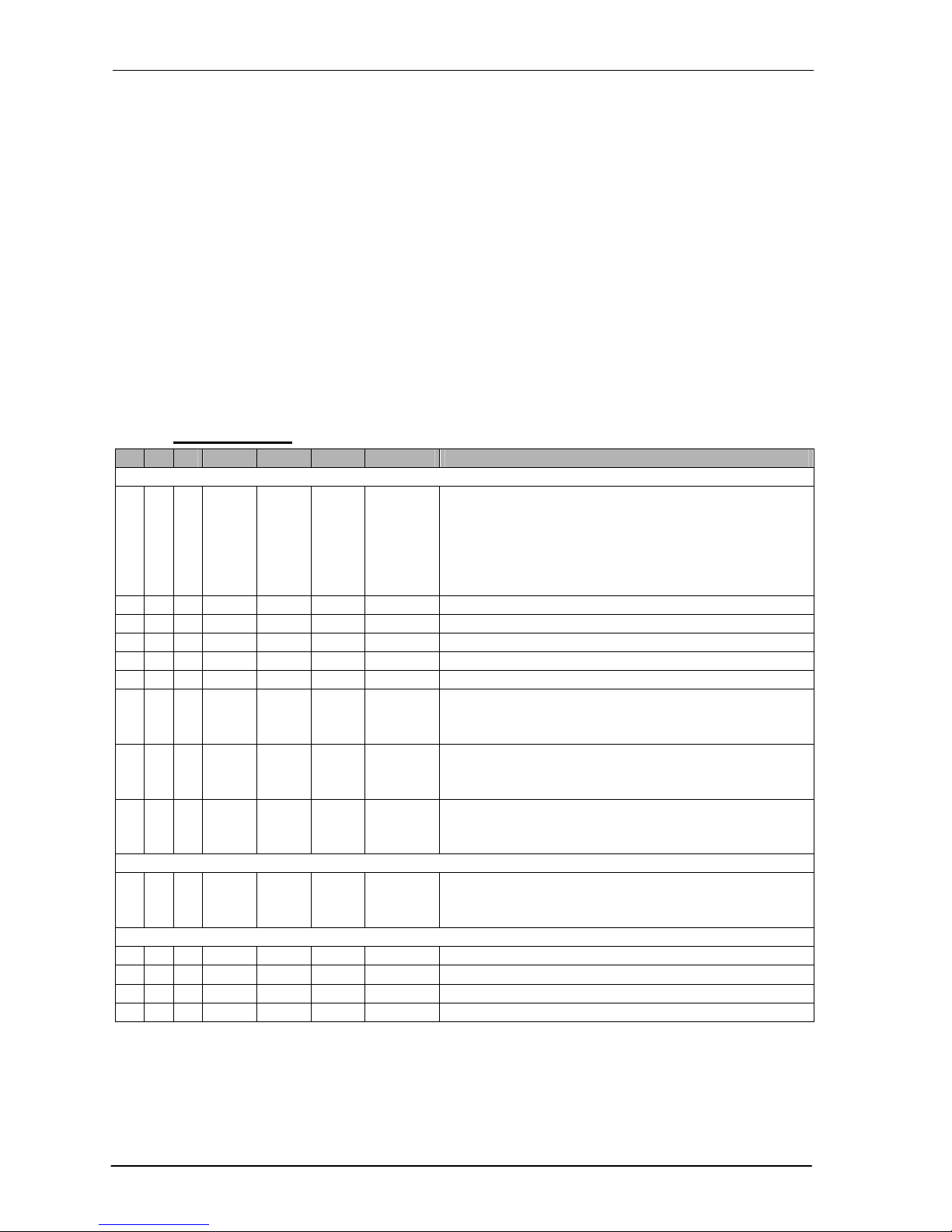
1.1.1 Operator-level
L C P Min Max Preset Unity Description
Bobbin thread counter and bobbin thread monitor
o 06 00 0 4 0 - Activate the bobbin thread counter
0 = off;
1 = Bobbin thread counter A;
2 = Bobbin thread counter B;
3 = Bobbin thread counter C;
4 = Bobbin thread monitor
o 06 01 0,1 999,9 300,0 x o0602
Reset value of the bobbin thread counter A
o 06 02 0,1 999,9 200,0 x o0604
Reset value of the bobbin thread counter B
o 06 03 0,1 999,9 100,0 x o0604
Reset value of the bobbin thread counter C
o 06 04 1 255 10 x stitches Factor of the bobbin thread counter A, B, and C
o 06 05 0 9999 0 stitches
Number of stitches for bobbin thread monitor
o 06 06 0 1 1 - Stopping motor if the counter has reached the value 0.
0 = off;
1 = on
o 06 07 0 1 1 - Sewing foot down after thread trimming.
0 = off;
1 = on
o 06 08 0 1 0 - Display of the bobbin thread counter value
0 = off;
1 = on
Needle cooling
o 13 00 0 1 0 - Needle cooling
0 = off;
1 = on
Light barrier
o 16 00 0 255 0 Stitches Compensating stitches normal stitch length
o 16 01 0 255 0 Stitches Compensating stitches long stitch length
o 16 10 0 255 0 Seams Number of light barrier seams
o 16 20 0 255 0 Stitches Number of stitches of the filter for knitted fabrics
Page 5

Operating manual part II
© 2013 Dürkopp Adler AG II-5
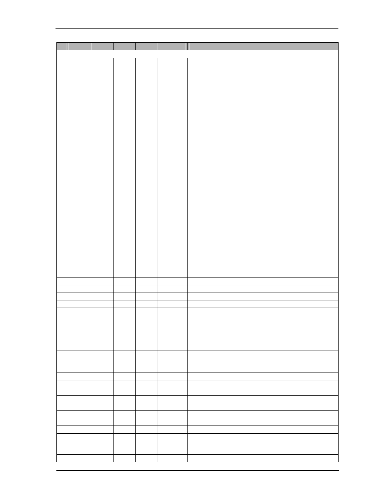
1.1.2 Technician-level
The technician's level must not be accessed by normal users. Modifications at this level must only be done by service
staff.
The technician's level is unlocked by the following key combination:
When switching on the control unit P (23)and the reset (18) button must be pressed at the same time.
This allows access to the technician's level.
Press A+ to get into the technician's level.
L C P Min Max Preset Unity Description
Backtack
t 00 00 300 6000 800 rpm Start backtack speed
t 00 01 0 254 8 10° Pre-control angle when switching on the backtack magnet.
(Switchover of forward backward at the bartack)
t
00 02 0 254 12 10° Pre-control angle when turning the backtack magnet off.
(Changing of backward forward at the bartack)
t 00 03 0 1 0 - Start backtack with the position 0 of the pedal interruptible.
0 = off;
1 = on
t 00 04 0 2 0 - Mode for the end of the start backtack.
0 = You sew further after the end;
1 = Machine stops and must be started by the pedal again;
2 = Thread performance after the start backtack
t 00 05 0 1 1 - Pedal release only to an additional route A
0 = off;
1 = on
t 00 06 0 500 0 ms Delay time up to the speed release after the start backtack
t 00 07 0 255 0 ms Decay time of the backtack magnet
t 00 10 300 6000 800 rpm End backtack speed
t 00 11 0 254 12 10° Pre-control angle when switching on the backtack magnet.
(Switchover of forward backward at the bartack)
t 00 12 0 254 13 10° Pre-control angle when turning the backtack magnet off.
(Changing of backward forward at the bartack)
t 00 13 0 1 0 - Backtack magnet stays switched on (simple with the last
backward way final backtack and multiple backtack ends) till
the needle has been reached the Pos. 2.
0 = off;
1 = on
t 00 20 300 6000 800 rpm Start multiple backtack speed (only at the stuffing program)
t 00 21 0 254 16 10° Pre-control angle when switching on the backtack magnet.
(Switchover of forward backward at the backtack) (only at the
stuffing program)
t 00 22 0 254 22 10° Pre-control angle when turning the backtack magnet off.
(Change of backward forward at the backtack) (only at the
stuffing program)
t 00 23 0 1 0 - Start backtack as a stuffing program.
0 = off;
1 = on
t 00 30 0 1 0 - Ornamental backtack
0 = off;
1 = on
t 00 31 0 2500 800 rpm Ornamental backtack speed
t 00 32 0 1000 150 ms Stop time at the ornamental backtack
t 00 35 0 1 1 - Reducing speed when shifting the feed dog
0 = off;
1 = on
Page 6

Operating manual part II
II-6 © 2013 Dürkopp Adler AG
L C P Min Max Preset Unity Description
t 00 36 0 6000 500 rpm Wished speed reduction when shifting the feed dog.
t 00 40 0 2 1 - Type of the start backtack, if the backtacking is toggled.
0 = Simple start backtack;
1 = Double start backtack;
2 = Start multiple backtack
t 00 41 0 2 1 - Type of the end backtack, if the backtacking is toggled.
0 = Simple end backtack;
1 = Double end backtack;
2 = End multiple backtack
t 00 44 0 3 3 - Mode of the manual backtack
0 = Manual backtack switched immediately;
1 = Manual backtack switched according to parameter
t 00 45 und t 00 46;
2 = If the manual backtack is pressed, the motor will stopped
in the position according to parameter t 0045 und t 00 46;
3 = If the manual backtack is pressed, the motor will stopped
in the position according to parameter t 0045 und t 00 46;
(Only with the parameter t 00 30 = 1)
t 00 45 0 1 0 - Switching on the manual backtack
0 = Needle below;
1 = Needle above
t 00 46 0 1 0 - Turning the manual backtack off
0 = Needle below;
1 = Needle above
t 00 50 0 999 100 ms Drive time of the backtack magnet in the time period t
1
t 00 51 5 100 100 % Pulse duty ratio in the time period t
1
t 00 52 0,0 600,0 100,0 s Drive time of the backtack magnet in the time period t2
(If you adjust 0s the backtack magnet will be driven
permanently)
t 00 53 5 100 40 % Pulse duty ratio in the time period t
2
t 00 54 0 1 1 - Increasing U
mag
when the backtack magnet will be driven
0 = No;
1 = Yes
Page 7
Operating manual part II
© 2013 Dürkopp Adler AG II-7
L C P Min Max Preset Unity Description
Thread Clamp
t 01 00 0 8 6 - Mode of the thread clamp
0 = on switching angle FK = t0101,
out switching angle FK = t0102,
Without FL;
1 = on switching angle FK = 108°,
out switching angle FK = 268°,
Without FL;
2 = on switching angle FK = 49°,
out switching angle FK = 110°,
Without FL;
3 = on switching angle FK = 49°,
out switching angle FK = 190°,
Without FL;
4 = on switching angle FK = 108°,
out switching angle FK 268°,
on switching angle FL = 108°,
out switching angle FL = 154°;
5 = on switching angle FK = 108°,
out switching angle FK = 268°,
on switching angle FL = 44°,
out switching angle FL = 154°;
6 = on switching angle FK = 30°,
out switching angle FK = 200°,
on switching angle FL = 50°,
out switching angle FL = 100°;
7 = Without FK,
on switching angle FL = t0111,
out switching angle FL = t0112;
8 = on switching angle FK = t0101,
out switching angle FK = t0102,
on switching angle FL = t0111,
out switching angle FL = t0112
t 01 01 0 359 30 ° on switching angle of the thread clamp
t 01 02 0 359 200 ° off switching angle of the thread clamp
t 01 11 0 359 50 ° on switching angle of the sewing foot lifting
t 01 12 0 359 100 ° off switching angle of the sewing foot lifting
t 01 13 0 100 100 %
Duty cycle of sewing foot lifting at mode 4-8
t 01 20 0 3 3 - Options of the thread clamp
0 = FK only at the seam beginning;
1 = FK at the seam beginning and at the turning back;
2 = FK at the seam beginning and at the sewing foot lifting;
3 = FK at the seam beginning, turning back and at the sewing
foot lifting
t 01 30 0 1 0 - NSB
0 = Off;
1 = Active with thread clamp
t 01 31 0 359 92 ° On switching angle of the additional thread clamp.
t 01 32 0 359 201 ° Off switching angle of the additional thread clamp.
t 01 33 0 359 105 ° On switching angle of the thread puller.
t 01 34 0 359 203 ° Off switching angle of the thread puller.
t 01 35 0 359 62 ° On switching angle of the thread tension.
t 01 36 0 359 94 ° Off switching angle of the thread tension.
t 01 50 0 999 100 ms Drive time of the thread clamp in the time period t1
t 01 51 5 100 100 % Pulse duty ratio in the time period t1
t 01 52 0,1 120,0 60,0 s Drive time of the thread clamp magnet in the time period t2
(If you adjust 0s the thread clamp magnet will be driven
permanently)
t 01 53 5 100 30 % Pulse duty ratio in the time period t
2
Page 8

Operating manual part II
II-8 © 2013 Dürkopp Adler AG
L C P Min Max Preset Unity Description
t 01 54 0 1 0 - Increasing U
mag
when the thread clamp magnet will be driven
0 = No;
1 = Yes
Thread trimmer
t 02 00 50 750 180 rpm Cutting speed
t 02 01 0 1 0 - Pedal position for starting the cutting process.
0 = Position -2;
1 = Position -1
t 02 10 0 359 120 ° on switching angle t 08 12 <= t 02 10 < t 02 11
t 02 11 0 359 245 ° off switching angle t 02 10 < t 02 11 <= t 08 13
t 02 20 0 255 0 ms Delay time for a repeated activation of the Cutting magnet.
t 02 21 0 255 0 ms Delay time for turning the cutting magnet off
Sewing foot lifting
t 03 00 0 1 1 - sewing foot lifting active
0 = No;
1 = Yes
t 03 10 0 255 80 ms Intermediate lag of the machine after switching the sewing
foot lifting off
t 03 11 0 255 40 ms Turn-on delay of the sewing foot lifting at speed 0
t 03 12 0,0 9,999 0,200 s Turn-on delay of the sewing foot lifting at the seam end
t 03 50 0 999 200 ms Drive time of the sewing foot lifting magnet in the time
period t
1
t 03 51 5 100 100 % Pulse duty ratio in the time period t1
t 03 52 0,0 600,0 60,0 s Drive time of the foot lifting magnet in the time period t2
(If you adjust 0s the thread clamp magnet will be driven
permanently)
t 03 53 5 100 40 % Pulse duty ratio in the time period t
2
t 03 54 0 1 1 - Increasing U
mag
when the foot lifting magnet will be driven
0 = No;
1 = Yes
Soft start
t 05 00 120 1000 400 rpm Soft start speed
t 05 01 1 99 2 Stitches Number of soft start stitches
Seam ways
t 07 00 0 2 0 - Treatment position-2 in seam ways.
0 = Demolition of the seam. The next seam way is sewn; The
seam is broken off with thread trimmer at the last seam of
the program.
1 = Demolition of the seam with thread performances (even if
inactive). The next seam process is a free seam.
2 = Demolition of the seam with thread performances (even if
inactive). Seam program is stopped.
t 07 01 0 1 0 - Automatic system business.
0 = off;
1 = on
Motor
t 08 00 500 9999 1600 rpm Maximum speed
t 08 01 10 400 150 rpm Minimal speed
t 08 02 10 1000 150 rpm Positioning speed
t 08 03 1 100 20 rpm/ms Acceleration ramp
t 08 04 1 100 20 rpm/ms Braking ramp
t 08 05 0 1 0 - Direction of rotation of the motor
0 = on the left;
1 = on the right
Page 9

Operating manual part II
© 2013 Dürkopp Adler AG II-9
L C P Min Max Preset Unity Description
t 08 06 0 2 1 - Motor brake at the normal stop
0 = Brakes for the duration of t0809;
1 = Brake durably actively at the stop
2 = Position will be hold permanently
t 08 07 0,1 6,0 3,0 A Holding current at the machine stop
t 08 08 0 255 40 - Reaction rate at changes of the needle position
t 08 09 0 999 200 ms Period of the motor brake
t 08 10 - - - - Setting the reference position
t 08 11 - - - - Setting the needle positions
t 08 12 0 359 120 ° Lower needle position (Position 1)
t 08 13 0 359 329 ° Thread lever up position (Position 2)
t 08 14 0 359 350 ° Direction finder position
t 08 15 0 359 245 ° on threading position
t 08 19 1 9999 650 - Pulley ratio=
(diameter motor / diameter machine) * 1000
t 08 20 - - - - Calibrating pedal
t 08 21 12 64 24 Steps Number of speed steps of the pedal
t 08 22 0 4 3 - Speed curve
t 08 23 10 255 90 ms Debouncing of the position-1
t 08 24 5 255 15 ms Debouncing of the position-2
t 08 25 0 1 0 - Choice of the pedal
0 = Analogous;
1 = Digital
t 08 26 0 1 0 - Invert the digital signal of the pedal
0 = No;
1 = Yes(Efka-Pedal with adapter )
t 08 30 0 1 1 - Shows the machine speed
0 = No;
1 = Yes
t 08 31 0 1 0 - Shows the current needle position
0 = No;
1 = Yes
t 08 32 0 1 0 - The Needle will move to the upper needle position if the
energy is on and the pedal was used.
0 = No;
1 = Yes
t 08 33 0 6 0 - Output of position signals
0 = No output;
1 = pos1;
2 = pos2;
3 = pos1 & pos2;
4 = machine running (ML);
5 = machine running (ML) & pos1;
6 = machine running (ML) & pos2;
t 08 34 0 255 0 ° Angle for the length of pos1
t 08 35 0 255 0 ° Angle for the length of pos2
t 08 36 10 9999 10 rpm Speed for the activation of motor running signal
t 08 40 500 9999 1500 rpm Speed limitation DB3000
t 08 41 500 9999 1800 rpm Speed limitation DB2000
t 08 50 10 500 180 rpm Speed for single stitch functions(For example half stitch and
full stitch)
Page 10

Operating manual part II
II-10 © 2013 Dürkopp Adler AG
L C P Min Max Preset Unity Description
Thread tension
t 09 00 0 3 2 ° Mode of the thread tension release and thread tension
reduction with active foot lifting.
0 = No thread tension release;
1 = Thread tension release in the seam;
2 = Thread tension release after thread trimming;
3 = Thread tension release in the seam and after thread
trimming.
t 09 01 0 1 1 ° Thread tension release by thread help
0 = No;
1 = Yes
t 09 02 0,0 2,55 0,0 s Delay time of the tread tension release after thread trimming.
(Only active if t 09 00 = 2 or 3)
t 09 03 0 2 0 ° Coupling thread tension with high lift walking foot
0 = No coupling;
1 = Additional thread tension when rapid stroke adjustment;
2 = Additional thread tension when reaching the high lift
walking foot speed limit;
t 09 10 0 359 225 ° on switching angle t 08 of 12 < = t of 09 10 < t 09 11 at the
trimming process
t 09 11 0 359 325 ° off switching angle t of 09 10 < t 09 of 11 < = t 08 13 at the
trimming process
t 09 20 0 255 0 ms Delay time for a repeated activation of the tension magnet at
the trimming process.
t 09 21 0 255 20 ms Delay time for turning the tension magnet off at the trimming
process
t 09 50 0 999 100 ms Drive time of the thread tension magnet in the time period t
1
t 09 51 5 100 100 % Pulse duty ratio in the time period t1
t 09 52 0,0 600,0 60,0 s Drive time of the thread tension magnet in the time period t2
(If you adjust 0s the thread tension magnet will be driven
permanently)
t 09 53 5 100 50 % Pulse duty ratio in the time period t
2
t 09 54 0 1 0 - Increasing U
mag
when the thread tension magnet will be driven
0 = No;
1 = Yes
High lift for walking foot
t 10 00 0 1 0 - High lift for walking foot
0 = No;
1 = Yes
t 10 01 0 9999 1800 rpm High lift walking speed
t 10 02 1 21 10 Step Lower speed break point
t 10 03 1 21 19 Step Upper speed break point
t 10 04 - - - - Show the actual position of the potentiometer and the actual
limitation of the speed
3: 2800
3: = actual position
2800 = speed limitation
t 10 06 0 1 0 - Speed limitation by rapid stroke adjustment
0 = Speed limitation on high lift walking speed for 500 ms;
1 = Permanently speed limitation on high lift walking speed;
t 10 07 0,0 2,55 0,0 s Run-out time of the high lift walking speed
t 10 08 0 255 0 Stiche Minimum number of stitches for high lift for walking foot
t 10 09 0 1 1 - Type of speed limitation potentiometer
0 = 9880 867105;
1 = 9880 867119;
Page 11

Operating manual part II
© 2013 Dürkopp Adler AG II-11
L C P Min Max Preset Unity Description
Function module
t 11 00 0 11 2 - Function of module 1 (X2.30)
0 = No Function;
1 = Additional thread tension;
2 = Switch stitch length;
3 = Single stitch with stitch length switching;
4 = Single stitch backwards with stitch length switching;
5 = Lift/lower roller;
6 = Lift/lower fabric end stop;
7 = Lift/lower edge trimmer;
8 = Switch stitch length (Triflex) with DB2000 and no
backtack;
9 = Fullness control with speed limitation DB3000;
10 = Fullness control without speed limitation DB3000;
11 = Step trimming
t 11 01 0 1 0 - Output of function module 1 (X2.30) inverted
0 = No;
1 = Yes
t 11 02 1 3 1 - State of the function module 1 (X2.30) after thread trimming
1 = Unchanged;
2 = Deactivated;
3 = Activated;
t 11 03 1 3 1 - State of the function module 1 (X2.30) after power on
1 = Unchanged;
2 = Deactivated;
3 = Activated;
t 11 30 0 11 1 - Function of module 2 (X2.20)
0 = Look at parameter t 11 00
t 11 31 0 1 0 - Output of function module 2 (X2.20) inverted
0 = No;
1 = Yes
t 11 32 1 3 1 - State of the function module 2 (X2.20) after thread trimming
1 = Unchanged;
2 = Deactivated;
3 = Activated;
t 11 33 1 3 1 - State of the function module 2 (X2.20) after power on
1 = Unchanged;
2 = Deactivated;
3 = Activated;
t 11 60 0 11 0 - Function of module 3 (X2.15)
0 = Look at parameter t 11 00
t 11 61 0 1 0 - Output of function module 3 (X2.15) inverted
0 = No;
1 = Yes
t 11 62 1 3 1 - State of the function module 3 (X2.15) after thread trimming
1 = Unchanged;
2 = Deactivated;
3 = Activated;
t 11 63 1 3 1 - State of the function module 3 (X2.15) after power on
1 = Unchanged;
2 = Deactivated;
3 = Activated;
t 11 90 0 999 100 ms Drive time of output FF3 in the time period t
1
t 11 91 5 100 100 % Pulse duty ratio in the time period t1
t 11 92 0,0 600,0 0,0 s Drive time of output FF3 in the time period t2
(If you adjust 0s the output FF3 will be driven permanently)
Page 12

Operating manual part II
II-12 © 2013 Dürkopp Adler AG
L C P Min Max Preset Unity Description
t 11 93 5 100 35 % Pulse duty ratio in the time period t2
t 11 94 0 1 0 - Increasing U
mag
when the output FF3 will be driven
0 = No;
1 = Yes
Turning Back
t 12 00 0 1 1 - Turning back
0 = No;
1 = Yes
t 12 01 10 180 30 ° Moving angle of rotation
t 12 02 10 255 40 ms Waiting time up to the turning back
Needle cooling
t 13 00 0 1 0 - Mode of the needle cooling
0 = Normal needle cooling;
1 = Needle cooling depending on speed
t 13 01 0,0 9,999 2,500 s Switch-off delay of needle cooling
t 13 02 100 9999 2000 rpm Speed for activate the needle cooling
t 13 03 0 1 0 - Needle cooling with foot lifting
0 = No;
1 = Yes
Roller
t 14 00 0 3 0 - Mode for lifting the roller
0 = No lifting;
1 = Lifting with sewing foot;
2 = Lifting with bartack;
3 = Lifting with bartack and sewing foot
t 14 01 0 1 0 - Lifting roller when enabling high lift for walking foot.
0 = No;
1 = Yes
t 14 02 0 1 0 - Stitch counting after sewing foot lifting till roller remains
lowered. (t 14 03)
0 = No;
1 = Yes
t 14 03 0 255 0 Stitches Number of stitches till lower the roller
Edge trimmer
t 15 00 0 7 0 - Mode for automatic lifting of the edge trimmer
0 = No automatic lifting;
1 = with foot lifting;
2 = After thread trimming or after stitch counting(t 15 04);
3 = After thread trimming or after stitch counting(t 15 04) and
with foot lifting;
4 = with backtack;
5 = with backtack and foot lifting;
6 = After thread trimming or after stitch counting (t 15 04) or
with backtack;
7 = After thread trimming or after stitch counting (t 15 04) or
with backtack and with foot lifting
t 15 03 0 255 0 Stitches Number of stitches to lowering the edge trimmer.
t 15 04 0 255 0 Stitches Number of stitches to lifting the edge trimmer
(t 15 00 = 2 od. 3).
t 15 10 0 1 0 - Motor of the edge trimmer active
0 = No;
1 = Yes;
t 15 11 0 1 0 - Electrical edge trimmer motor will stop by sewing stop
0 = No;
1 = Yes;
t 15 12 0 100 50 % Minimum duty cycle of edge trimmer motor.
t 15 13 0 100 95 % Maximum duty cycle of edge trimmer motor.
Page 13

Operating manual part II
© 2013 Dürkopp Adler AG II-13
L C P Min Max Preset Unity Description
t 15 14 0 9999 1500 rpm Maximum speed for the maximum duty cycle
t 15 20 0,1 2,55 0,50 s Delay after switch off the edge trimmer for the step trimming
process
t 15 21 0,1 2,55 0,50 s Delay for move out the step trimmer
t 15 22 0,1 2,55 0,50 s Time for blowing during move out the step trimmer
t 15 23 0,1 2,55 0,50 s Delay for switch off the blower after sew stop
t 15 24 0,1 2,55 0,50 s Delay for switch on the edge trimmer after move out/in the
step trimmer.
Light barrier
t 16 00 50 9999 1000 rpm Speed for compensating stitches
t 16 01 1 3 3 - Light barrier mode
1 = Detection on seam begin
2 = Detection on seam end
3 = Detection on seam begin and seam end
t 16 02 0 1 0 - Mode for the seam begin
0 = Release seam start with light barrier;
1 = Start the seam with foot pedal switch and light barrier;
t 16 03 0 1 0 - Filter for knitted fabrics
0 = Off;
1 = On
t 16 04 0 1 0 - Light barrier sensing
0 = uncovered;
1 = covered
Electronic Hand wheel
t 17 00 0 1 0 - Electronic hand wheel active
0 = No;
1 = Yes (t 51 32 und t 51 33 = 0)
t 17 01 1 255 6 - Step for electronic hand wheel
t 17 02 0 1 0 - Direction electronic hand wheel
0 = right;
1 = left
Thread wiper
t 20 00 0 1 0 - Thread wiper
0 = Off;
1 = On
t 20 01 10 255 100 ms On Timer for thread wiper
Stitch length switching
t 30 00 0 2 2 - Speed limitation with long stitch length.
0 = Off;
1 = Speed limitation (DB2000)
2 = Speed limitation (DB3000)
t 30 01 0 2 0 - Stitch length during backtack
0 = Actual stitch length(long/normal);
1 = Normal stitch length
2 = Long stitch length
t 30 02 0 2 0 - Stitch length after thread trimming
0 = Manual chosen stitch length;
1 = Normal stitch length;
2 = Long stitch length;
Stitch length reduction
t 31 00 0 255 0 Stitches Number of stitches with stitch length reduction at seam begin.
t 31 01 0 2 1 - Stitch length reduction on thread trimming process.
0 = Off;
1 = Stitch length reduction for a hole stitch;
2 = Stitch length reduction only in the trimming process
Page 14

Operating manual part II
II-14 © 2013 Dürkopp Adler AG
L C P Min Max Preset Unity Description
Machine run blockage
t 50 00 0 1 1 - Machine run blockage
0 = off;
1 = on
t 50 01 0 1 0 - The mode of operation from machine run blockage switch
0 = NC;
1 = NO
t 50 02 0 1 1 - Emergency shutdown of the motor or motor places
0 = Emergency shutdown;
1 = Direct positioning
Miscellaneous of the control
t 51 00 - - - - Showing software version
t 51 01 - - - - Showing control serial number
t 51 02 0 1 0 - Show the analog value (t 51 12) during sewing process.
0 = No;
1 = Yes
t 51 04 - - - - Showing machine class and –sub class
t 51 05 - - - - Showing hours of operation
t 51 06 - - - - Showing stitches of operation
t 51 07 - - - - Showing piece counter
t 51 10 0 4 - - Load of parameters
0 = Nothing;
1 = Sewing data from the dongle;
2 = Sewing data of the backup area;
3 = Seam ways from the Dongle
4 = Master reset
t 51 11 0 3 - - Store of parameters
0 = Nothing;
1 = Sewing data to the dongle;
2 = Sewing data to the backup area;
3 = Seam ways to the Dongle
Page 15

Operating manual part II
© 2013 Dürkopp Adler AG II-15
L C P Min Max Preset Unity Description
t 51 12 - - - - Hardware-Test
Bold Inputs or Outputs are only available at DACclassic
controls.
1.Analog
Um: Supply Voltage in V
U24: Supply Voltage for Outputs in V
Imo: Current of the 24V supply
PAn: Analog value of the pedal
Nre: X1.4 Analog Input
Ian: X1.1 Analog Input
I2T: I²T of the motor (Attention: Footpedal Switch and
Motor are activated!)
2.Inputs
X1.5: Manual Backtack
X1.6: Nedle up/down
X1.7: Additional thread tension (module 2)
X1.8: Switch stitch length (module 1)
X1.9: Input function module 3 (module 3)
X1.10: Limitation DB3000
X1.11: Machine run blockage
X1.12: Bobbin thread monitor
X1.13: Light barrier
X1.14: Backtack suppression/recall
X2.1: High lift for walking foot (not stored)
X2.2: High lift for walking foot (stored)
X2.3: No Function
X2.4: No Function
X2.6: No Function
X2.7: No Function
3.Outputs
X1.15: Output function module 3 (module 3)
X1.17: No Function
X1.18: Thread clamp
X1.20: Additional thread tension (module 2)
X1.21: No Function
X1.22: LED function module 3 (module 3)
X1.23: LED bobbin thread monitor left
X1.24: LED Backtack suppression/recall
X1.25: LED bobbin thread monitor right
X1.26: No Function
X1.27: No Function
X1.28: Needle cooling
X1.29: LED switch stitch length (module 1)
X1.30: Switch stitch length (module 1)
X1.31: LED additional thread tension (module 2)
X1.32: High lift for walking foot
X1.34: Backtacking
X1.35: Sewing foot lifting
X1.36: Thread tension
X1.37: Thread trimmer
t 51 13 - - - - Disturbance reports show the last on 10
t 51 14 0 1 - - Reset of the service counter
0 = No;
1 = Yes
Page 16

Operating manual part II
II-16 © 2013 Dürkopp Adler AG
L C P Min Max Preset Unity Description
t 51 20 0 22 3 - Function of the bartack input (machine connector Pin 5)
0 = no function;
1 = on threading help;
2 = Bartack suppression/recall;
3 = Manual bartack;
4 = Half stitch;
5 = Full stitch;
6 = Direction finder position;
7 = Turning back
8 = Input function module 1 (look at t 11 00);
9 = Input function module 2 (look at t 11 30);
10 = Input function module 3 (look at t 11 60);
11 = Needle up
12 = Ornamental Backtack;
13 = Needle cooling;
14 = Thread wiper
15 = Normal stitch length on backtack
16 = Machine run blockage (N.O.)
17 = Machine run blockage (N.C.)
18 = Switch high lift for walking foot (not stored)
19 = Switch high lift for walking foot (stored)
20 = Speed limitation (DB2000)
21 = Speed limitation (DB3000)
22 = Ligth barrier
t 51 21 0 22 2 - Function of the bartack toggle input (machine connector Pin
14)
0 = Look at parameter t 51 20
t 51 22 0 22 4 - Function of the needle up/down input (machine connector Pin
6)
0 = Look at parameter t 51 20
t 51 23 0 22 8 - Function of the input FF1 (machine connector Pin 8)
0 = Look at parameter t 51 20
t 51 24 0 22 12 - Function of the input FF2 (machine connector Pin 7)
0 = Look at parameter t 51 20
t 51 25 0 22 0 - Function of the input FF3 (machine connector Pin 9)
0 = Look at parameter t 51 20
t 51 26 0 22 0 - Function of the input DB3000 (machine connector Pin 10)
0 = Look at parameter t 51 20
t 51 27 0 22 0 - Function of the input light barrier (machine connector Pin 13)
0 = Look at parameter t 51 20
t 51 28 0 22 18 - Function of the input IN_EXT1 (additional input interface Pin
1)
0 = Look at parameter t 51 20
t 51 29 0 22 19 - Function of the input IN_EXT2 (additional input interface Pin
2)
0 = Look at parameter t 51 20
t 51 30 0 22 0 - Function of the input IN_EXT3 (additional input interface Pin
3)
0 = Look at parameter t 51 20
t 51 31 0 22 0 - Function of the input IN_EXT4 (additional input interface Pin
4)
0 = Look at parameter t 51 20
t 51 32 0 22 0 - Function of the input IN_EXT5 (additional input interface Pin
6)
0 = Look at parameter t 51 20
t 51 33 0 22 0 - Function of the input IN_EXT6 (additional input interface Pin
7)
0 = Look at parameter t 51 20
Page 17

Operating manual part II
© 2013 Dürkopp Adler AG II-17
L C P Min Max Preset Unity Description
OP1000
t 52 00 0 15 4 - Contrast of the display of the OP1000
t 52 01 0 1 1 - Button receipt active
0 = No;
1 = Yes
t 52 20 0 22 12 - Function of the input “F
0 = no function;
1 = on threading help;
2 = Bartack suppression/recall;
3 = Manual bartack;
4 = Half stitch;
5 = Full stitch;
6 = Direction finder position;
7 = Turning back
8 = Input function module 1 (look at t 11 00);
9 = Input function module 2 (look at t 11 30);
10 = Input function module 3 (look at t 11 60);
11 = Needle up
12 = Ornamental Backtack;
13 = Needle cooling;
14 = Thread wiper
15 = Normal stitch length on backtack
16 = Machine run blockage (N.O.)
17 = Machine run blockage (N.C.)
18 = Switch high lift for walking foot (not stored)
19 = Switch high lift for walking foot (stored)
20 = Speed limitation (DB2000)
21 = Speed limitation (DB3000);
22 = Light barrier
t 52 40 0 1 0 - Key lock for the initial bartack buttons
0 = No;
1 = Yes
t 52 41 0 1 0 - Key lock for the final bartack buttons
0 = No;
1 = Yes
t 52 42 0 1 0 - Key lock for the thread buttons
0 = No;
1 = Yes
t 52 43 0 1 0 - Key lock for the seam program buttons
0 = No;
1 = Yes
t 52 44 0 1 0 - Key lock for the programming buttons
0 = No;
1 = Yes
Page 18

Operating manual part II
II-18 © 2013 Dürkopp Adler AG
1.1.3 Developer-level
L C P Min Max Preset Unity Description
Bartack
d 00 01 0 359 15 ° Mechanical switching angle of the bartack
Thread trimmer
d
02 00 0 359 180 - The FA speed shall angle be reached before switching on
the magnets.
d
02 01 0 1 0 - Chainstitch mode
0 = No;
1 = Yes
d
02 02 0 1 0 - Increasing U
mag
in the thread trimming process
0 = No;
1 = Yes
Seam ways
d 07 00 150 9999 1000 rpm Speed limitation for seam ways
d 07 01 1 20 6 Stitches Stitches for the speed limitation by seam ways
Motor
d 08 00 1 9999 2000 rpm Maximum motor speed
d 08 01 1 100 25 rpm/ms Maximum acceleration or deceleration
d 08 02 0 50 20 Kgcm² Mechanical inertia
d 08 04 0 255 0 Inc Additional increments at the brake ramp
d 08 05 0 1 0 - Half acceleration and brake ramp if I²t increase above 70%.
0 = No;
1 = Yes
d 08 10 0,1 100,0 1,7 Ohm Stator resistance
d 08 11 1 200 5 mH Stator inductance
d 08 12 0,1 200,0 40,5 V/1000rpm EMK
d 08 13 0,1 15,00 12,00 A Maximum stator current
d 08 14 1 10 2 - Pole couple number
d 08 20 0 255 44 - Factor Kpn of the speed control
d 08 21 0 255 23 - Factor Kin of the speed control
d 08 22 0 255 0 - Factor Kdn of the speed control
d 08 23 0 255 24 - Pre control of the speed control in the breaking sequence
d 08 30 0 255 0 - Factor Kps of the distance control
d 08 31 0 255 0 - Factor Kis of the distance control
d 08 32 0 255 0 - Factor Kds of the distance control
d 08 40 0 255 82 - Factor Kpx of the position control
d 08 41 0 255 64 - Factor Kdx of the position control
d 08 42 0 255 16 Inc Increments for the add-on connection of the PD situation
control system
d 08 43 0 1000 0 2,857° Angle to the positioning
d 08 44 0 1000 16 Inc Increments for the position speed
d 08 51 0 1 0 - endurance test active
0 = No;
1 = Yes
d 08 52 0,0 99,99 5,00 s Period motor on
d 08 53 0,0 99,99 5,00 s Period motor off
d 08 54 1 9999 900 s Period of the endurance test
d 08 55 0 2000 180 rpm Speed for the reference drive
Thread tension
d 09 01 5 100 50 % Pulse duty ratio at the on threading help
Page 19

Operating manual part II
© 2013 Dürkopp Adler AG II-19
L C P Min Max Preset Unity Description
Miscellaneous
of the control
d 51 00 1 255 40 ms Period for raising off Umag on 33V
d 51 01 1 255 5 ms Period for the DeEnergizer process
d 51 02 0,1 16,00 16,00 kHz Adjust the PWM frequency
d 51 03 - - - - Showing machine serial number
d 51 04 - - - - Showing production date
d 51 10 0,0 999,9 0,0 x d5111 Reset value of the service counter ( 0 means disabled)
d 51 11 1 255 1 x 10000St service counter factor
d 51 12 1 255 1 x d5111 repeat the info message
Page 20

Operating manual part II
II-20 © 2013 Dürkopp Adler AG
1.2 Sets of parameters for class 838
Parametersatz
838-x70522-
1,55
838-x70522-M
Für
Unterklassen
838-170522-
1,55,
838
-
270522
-
838-170522-M,
838-270522-M
L C P Preset Preset
t 08 04 20 30
t 08 05 0 1
t 08 10 - t 08 19 650 1000
t 51 26 0 21
d 08 01 25 40
d 08 04 0 100
d 08 10 1,7 2,2
d 08 11 5 9
d 08 12 40,5 54,0
d 08 13 12,00 11,00
d 08 14 2 3
d 08 21 23 30
d 08 30 0 6
d 08 31 0 3
d 08 32 0 6
d 08 40 82 76
Page 21

Operating manual part II
© 2013 Dürkopp Adler AG II-21
2 Error-, warning- and info-messages
The control DAC
basic
or DAC
classic
has got three groups of messages. In the following table this three groups are
described.
Level
Acronym
Description
Error Err Error
Switch off the control and eliminate the problem .
Warning Wrn Eliminate the state that caused to the warning. The control will normally worked.
Information Inf Information push the OK-button
Further working should be possible. It could be that only only emergency run features are
possible.
Level
Code
Error description
Corrective
Error 1000 Sewing motor encoder plug (Sub-D, 9
pin) not connected.
- Insert the encoder lead into the control unit. Use the
right interface.
Error 1001 Sewing motor error
Sewing motor plug (AMP) is not
connected.
- Check the connection and if necessary plug in.
- Test sewing motor phases (R= 2.8 Ohm, high
resistance compared with PE)
- Replace encoder
- Replace sewing motor
- Replace control unit
Error 1002 Sewing motor insulation error - Check motor phase and PE for low-resistance
connection
- Replace encoder
- Replace sewing motor
Error 1004 Sewing motor turning in the wrong
direction
- Replace encoder
- Check that the motor plug is in the right place and
change if necessary
- Check wiring in the machine distributor and change if
necessary
- Test motor phases and check for value
Error 1005 sewing motor blocked -Eliminate sluggish movement in the sewing machine
- Replace encoder
- Replace sewing motor
Error 1006 maximum speed exceeded - Change the Encoder
- Reset the control unit
- Check the machine sub class ( t 51 04)
Error 1007 Errors in the reference movement - Change the encoder
- Eliminate sluggish movement in the sewing machine
Error 1008 Error motor encoder - Change the encoder
Error 1010 Plug from the external synchronizer is
not connected
- Insert the plug from the external synchronizer into the
control unit. Use the right interface (Sync).
-Only needed by machines with pulley ratio
Error 1011 Missing Z-impulse from then encoder -
Switch off the control. Move the hand wheel and switch
the control on.
-Otherwise check the encoder
Error 1012 Error external synchronizer -Change the external synchronizer
Error 1052 Excess sewing motor current, internal
current increase >25A
- check the selection of the machine class
- Replace control unit
- Replace the motor
Error 1053 Excess sewing motor voltage, internal
voltage increase
- check the selection of the machine class
- Replace control unit
Error 1054 Internal short circuit - Replace control unit
Error 1055 Sewing motor overload - Eliminate sluggish movement in the sewing machine
- Replace encoder
- Replace sewing motor
Information 1203 Position not reached (for thread cutting,
turning round etc. )
- Check controller settings and if necessary change,
mechanical changes to the machines, e.g. thread
cutter setting, belt tension etc.)
Page 22

Operating manual part II
II-22 © 2013 Dürkopp Adler AG
Level
Code
Error description
Corrective
- Check the thread lever up position (Position 2)
Error 3100 AC RDY timeout , intermediate circuit
voltage has not reached the defined
threshold in the given time.
- Check mains voltage
- If mains voltage OK, replace control unit
Error 3101 High voltage error, mains voltage
>290V for some time
- Check mains voltage, if rated voltage exceeded
permanently - stabilise or use generator
Error 3102 Low voltage failure (2nd threshold)
(mains voltage < 150V AC)
- Check mains voltage
- Stabilise mains voltage
- Use generator
Information 3103 Low voltage warning (1st threshold)
(mains voltage < 180V AC)
- Check mains voltage
- Stabilise mains voltage
- Use generator
Warning 3104 Pedal position is not at position 0 When switching on the control unit, take foot off pedal
Error 3105 Short circuit U24V - 37 pin Take plug out, if error 3105 continues, replace
control unit
- Test inputs/ outputs for 24V short circuit
Error 3106 Overload U24V (I²T) - one or more of the magnets faulty
Error 3107 Pedal not connected - connect analogue pedal
Information 3108 Speed limiting because the power
supply is to low
- check your power supply
Warning 3109 Maintaining safety - Check the tipping sensor on the machine
Information 3150 Maintenance required (info) - For information on lubricating the machine see the
machine's service instructions
Warning 3151 Maintenance requir
ed (continue only
when parameters reset
t 51 14, see machine's operating
instructions)
-
carry out service urgently, see machine's service
instructions
Information 3215
Bobbin thread ounter (info value 0
reached)
- Change reel, set counter value - press counter reset
button
Information 3216 Bobbin thread monitor left - Change left bobbin
Information 3217 Bobbin thread monitor right - Change right bobbin
Information 3218 Bobbin thread monitor left and right - Change left and right bobbin
Error 6353 Internal EEprom communication error - Switch off control unit, wait until the LEDs go out and
turn on again.
Error 6354 External EEprom communication error - Switch off control unit, wait until the LEDs go out and
check the connection of the mach-ID. Turn the control
on.
Information 6360 No valid data on external EEprom - Update software. The internal data structures are not
compatible with the external data memory
Information 6361 No external Eeprom connected - Plug in mach ID
Information 6362 No valid data on internal EEprom - Check connection mach-ID
- Switch off control unit, wait until the LEDs go out and
turn on again.
- Update software. The internal data structures are not
compatible with the external data memory
Information 6363 No valid data on internal or external
EEprom
(only emergency run features)
- Check connection mach-ID
- Switch off control unit, wait until the LEDs go out and
turn on again.
- Update software. The software version is not
compatible with the internal data memory
Information 6364 No valid data on internal EEprom and
external EEprom not connected
(only emergency run features)
- Check connection mach-ID
- Switch off control unit, wait until the LEDs go out and
turn on again.
- Update software. The internal data structures are not
compatible with the external data memory
Information 6365 Internal EEprom faulty - Replace control unit
Information 6366 Internal EEprom faulty and external - Replace control unit
Page 23

Operating manual part II
© 2013 Dürkopp Adler AG II-23
Level
Code
Error description
Corrective
data invalid
(only emergency run features)
Information 6367 Internal EEprom faulty and external not
connected
(only emergency run features)
- Replace control unit
Information 7801 Wrong software version
(Only DAC
classic
. Further using only of
DAC
basic
functions)
- Update software
- Replace control unit
Information 7802 Update failure
(Only DAC
classic
. Further using only of
DAC
basic
functions)
- Update software
- Replace control unit
Information 7803 Communication Error
(Only DAC
classic
. Further using only of
DAC
basic
functions)
- Restart the control unit
- Update software
- Replace control unit
Error 8401 Watchdog - Update software
- Replace control unit
Error 8402-
8405
Internal failure - Update software
- Replace control unit
Error 8406 Checksum Error - Update software
- Replace control unit
Error 8501 Software Protection - the DA tool must always be used to update software
 Loading...