

Page 1

Contents Page:
Part 4: Service manual, class 743-221
1. General
. . . . . . . . . . . . . . . . . . . . . . . . . . . . . . . . . . . . . . . . . . . . . . . . . 3
2. Adjusting the upper part of the machine
2.1 Gauges . . . . . . . . . . . . . . . . . . . . . . . . . . . . . . . . . . . . . . . . . . . . . . . . . 4
2.2 Description and adjustment of integral adjusting disc . . . . . . . . . . . . . . . . . . . . . . . 5
2.3 Arm-shaft crank . . . . . . . . . . . . . . . . . . . . . . . . . . . . . . . . . . . . . . . . . . . . 6
2.4 Upper-thread tensioner release . . . . . . . . . . . . . . . . . . . . . . . . . . . . . . . . . . . 7
2.5 Thread take-up spring . . . . . . . . . . . . . . . . . . . . . . . . . . . . . . . . . . . . . . . . . 8
2.6 Needle-bar height . . . . . . . . . . . . . . . . . . . . . . . . . . . . . . . . . . . . . . . . . . . 9
2.7 Shuttle settings . . . . . . . . . . . . . . . . . . . . . . . . . . . . . . . . . . . . . . . . . . . . . 11
2.7.1 Loop lift and distance between shuttle beak and needle . . . . . . . . . . . . . . . . . . . . . . 11
2.7.2 Shuttle-drive housing . . . . . . . . . . . . . . . . . . . . . . . . . . . . . . . . . . . . . . . . . 12
2.8 Bobbin-housing holder . . . . . . . . . . . . . . . . . . . . . . . . . . . . . . . . . . . . . . . . . 13
2.9 Light barrier of residual-thread monitor . . . . . . . . . . . . . . . . . . . . . . . . . . . . . . . 14
2.10 Bobbin winder . . . . . . . . . . . . . . . . . . . . . . . . . . . . . . . . . . . . . . . . . . . . . 15
2.11 Position sensor . . . . . . . . . . . . . . . . . . . . . . . . . . . . . . . . . . . . . . . . . . . . . 16
2.12 Replacing the right-hand arm-shaft bearing . . . . . . . . . . . . . . . . . . . . . . . . . . . . . 18
2.13 Lubrication . . . . . . . . . . . . . . . . . . . . . . . . . . . . . . . . . . . . . . . . . . . . . . . 19
2.13.1 Shuttle lubrication . . . . . . . . . . . . . . . . . . . . . . . . . . . . . . . . . . . . . . . . . . . 20
3. Adjusting the sewing machine
3.1 Thread clipper . . . . . . . . . . . . . . . . . . . . . . . . . . . . . . . . . . . . . . . . . . . . . 21
3.1.1 Fitting and removing the blades . . . . . . . . . . . . . . . . . . . . . . . . . . . . . . . . . . . 22
3.1.2 Replacing the piston . . . . . . . . . . . . . . . . . . . . . . . . . . . . . . . . . . . . . . . . . . 24
3.2 Folding table . . . . . . . . . . . . . . . . . . . . . . . . . . . . . . . . . . . . . . . . . . . . . . 25
3.2.1 Retraction of folding table . . . . . . . . . . . . . . . . . . . . . . . . . . . . . . . . . . . . . . . 26
3.2.2 Angle adjustment, switch point b03 . . . . . . . . . . . . . . . . . . . . . . . . . . . . . . . . . 27
3.3 Transport carriage . . . . . . . . . . . . . . . . . . . . . . . . . . . . . . . . . . . . . . . . . . . 28
3.3.1 Overrun protection . . . . . . . . . . . . . . . . . . . . . . . . . . . . . . . . . . . . . . . . . . . 29
3.4 Shaping module . . . . . . . . . . . . . . . . . . . . . . . . . . . . . . . . . . . . . . . . . . . . 30
3.4.1 Shaping-module guide roller . . . . . . . . . . . . . . . . . . . . . . . . . . . . . . . . . . . . . 30
3.4.2 Shaping-module pressure cylinder . . . . . . . . . . . . . . . . . . . . . . . . . . . . . . . . . . 31
3.4.3 Shaping-module closing movement . . . . . . . . . . . . . . . . . . . . . . . . . . . . . . . . . 32
3.4.4 Adjusting the shaping module . . . . . . . . . . . . . . . . . . . . . . . . . . . . . . . . . . . . 33
4. Maintenance unit
. . . . . . . . . . . . . . . . . . . . . . . . . . . . . . . . . . . . . . . . . . . 34
5. Maintenance
. . . . . . . . . . . . . . . . . . . . . . . . . . . . . . . . . . . . . . . . . . . . . . 35
6. Summary of adj u stments
. . . . . . . . . . . . . . . . . . . . . . . . . . . . . . . . . . . . . . 36
Page 2

Page 3

1. General
This service manual describes the adjustment of the
743-221
model
sewing machi n e i n an expedient sequen c e.
IMPORTANT !
Various adjustments are mutually interdependent.
The adjustme nt pro c es s m ust therefore be ca r ri ed ou t i n th e order
given.
IMPORTANT !
The activities described in this Service manual may only be carried out
by specialists or by persons with appropriate training.
Danger of breakage
Before the sewi n g mac h i ne is re- started followi ng di sm an tl i n g t he
necessary adjustments must be carried out as specified in this service
manual.
Avoidance of damage to the material clamps:
The sewing machine must never be operated without material. This
also applies to ad j us t me nt wo r k an d f un c ti o n-t es t i ng .
Adjustment work on stitch-forming components
For all adjustments of stit c h-forming components a flawles s n ew
needle must be fi t te d.
Caution: danger of injury
Before all repair, conversion and maintenance work:
–
turn off the main switch
–
isolate the s ew i ng ma c hi n e f rom the pneumatic s up pl y.
Exception:
Adjustment work which is carried out with testing, adjustment or
sewing programs of the control device.
Adjustment work and function-testing with the sewing machine
running
–
When carryin g o ut ad jus t me nt wo r k an d f un c ti o n-t es t ing wi t h t he
machine runni ng , c o mp l y wi t h a l l safety measures a nd ta k e t he
utmost care.
Pedal
–
In the sewing pr o gr a ms the sewing mac hi n e c a n b e s t art ed by
inadvertently depressing the pedal.
IMPORTANT !
All colour-m ar k e d components are f ac t ory - se t. These settings sh ou l d
only be altere d b y s pe c i ali s t s .
3
Page 4
2. Adjusting the upper part of the machine
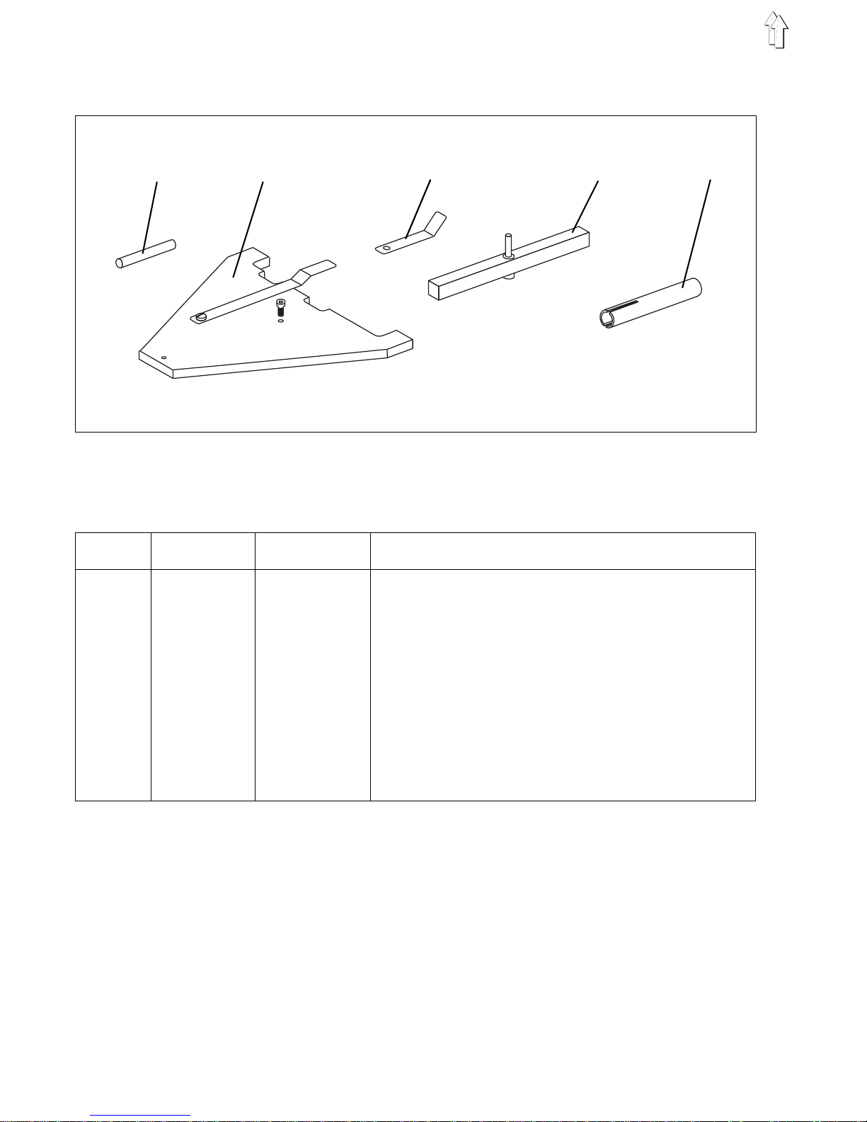
2.1 Gauges
With the adjustment gauges listed below the sewing machine can be
precisely adjusted and tested.
item adjustment order no. use
gauge
1
adjusting pin 9301 022608 lock sewing machine in positions A -
F
2
gauge 0935 107077 ali g n t r an s po rt c a r ri ag e, c he c k ref er e nc e po i nt , g ui d e
roller and needle centre
3
feeler gauge 0933 080200 che c k an d a dj u s t g ui d e ro l l er
4
gauge 0935 107071 align needle-bar height and shuttle-drive housing
5
sleeve 0935 107090 ali g n r e s idu al - t hr e ad mo ni t or
12
345
4
Page 5
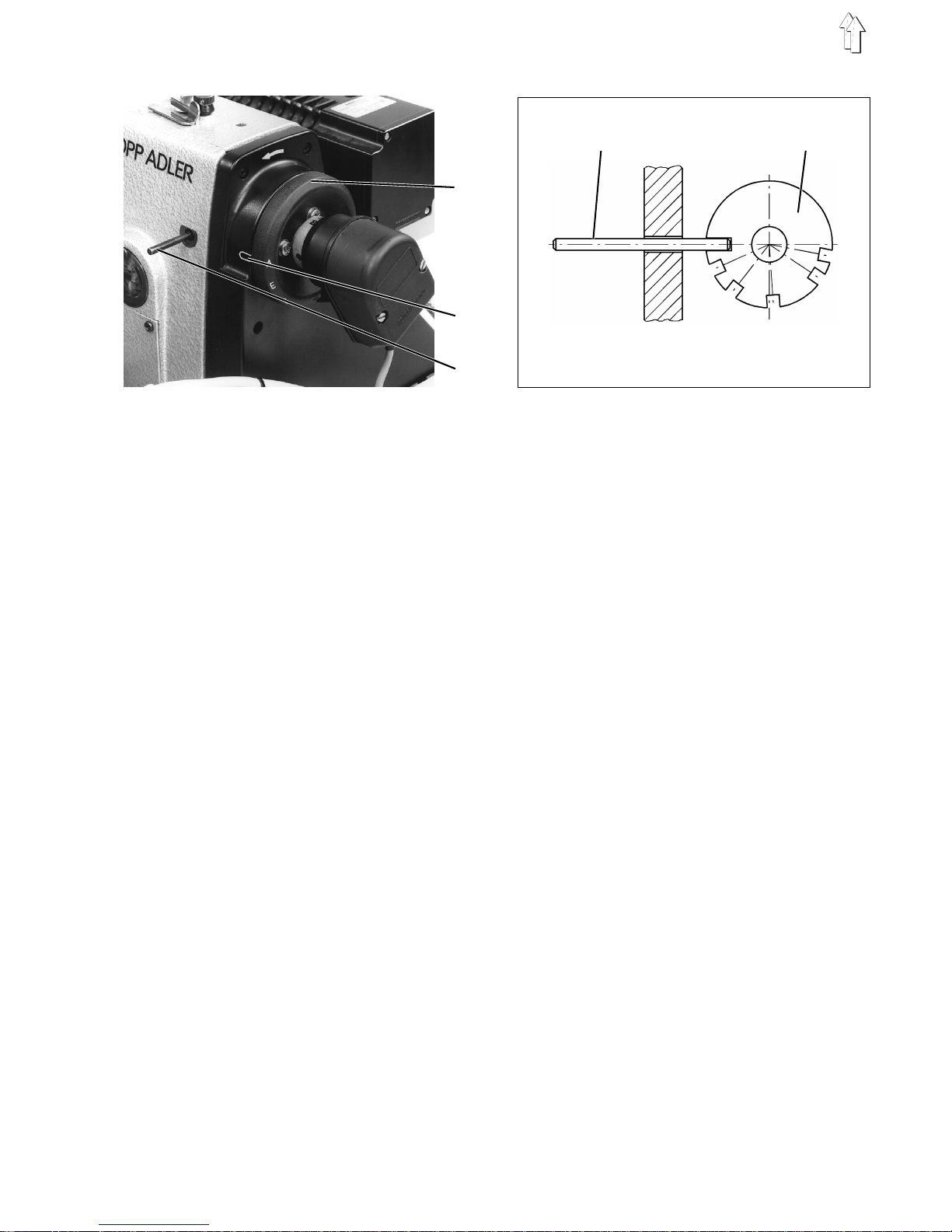
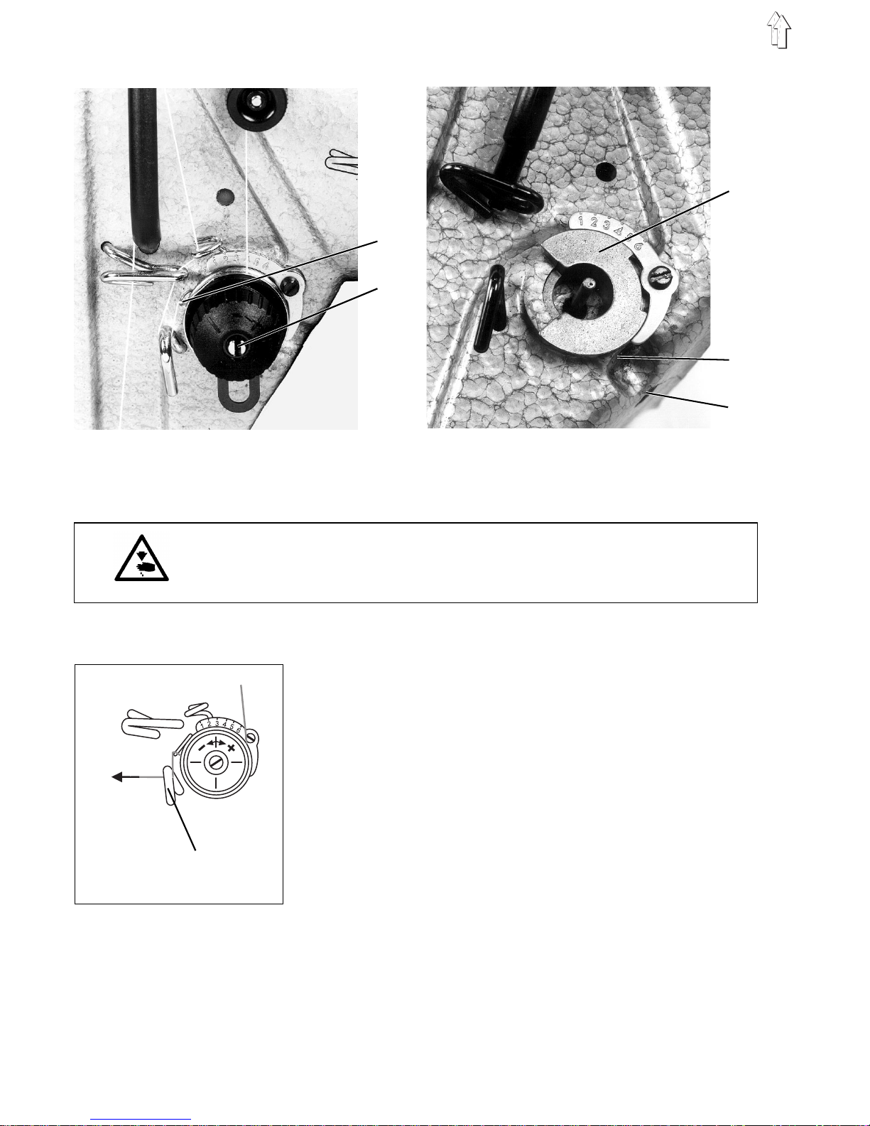
2.2 Descripti on and adjustment of integral adjusting disc
The sewing ma chi n e c a n b e l o c k ed i n a ll ad j us t me nt po s i ti o ns w i th
locking pin 3 and the integral adjusting disc 4 on the cogged-belt
pulley of the arm shaft.
The adjusting disc has 6 notches which are marked on the
handwheel 1 by th e l e tt er s A, B, C, D, E and F. In conjunction with
marking 2 the letters indicate the position of the notches in which the
machine can be l o ck ed with pin 3.
Notch A (loop-lift position) is deeper than the other notches.
The following adjustments can be carried out in the various positions:
A
adjusting di sc w i th r es p ect to the groove in the arm-shaft c r a nk,
belt wheel, l oo p l i f t, di s t an c e o f s h ut tl e be ak f r om ne ed l e
B
- no function -
C
2nd needle position (raised thread-lever position)
D
- no function -
E
needle-bar hei g ht
F
- no function -
1
2
3
A
C
E
D
B
3 4
F
5
Page 6
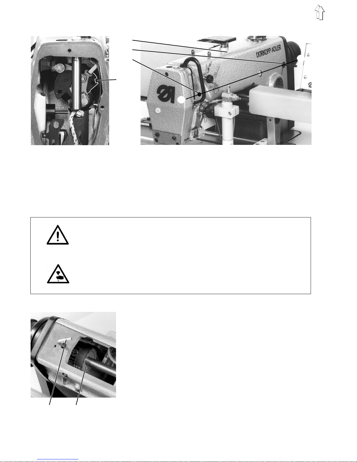
2.3 Arm-shaft crank
Regulation and inspection
The groove 4 and notch A of the adjusting disc on the cogged-belt
pulley must coincide on the
X - Y
line.
–
Lock the arm sh af t with a locking pi n or a 5 m m Ø p in i n th e
arm-shaft gr oo v e 4 (th r ou gh ho l e 3 ) .
–
It must be possible to pass the locking pin through the hole 2 in
position A into the integral adjusting disc.
IMPORTANT !
Adjustments carried out with the adjusting disc will only be correct if
the disc itself has been adjusted as described below.
If the arm shaft is moved, all subsequent settings must be checked
and adjusted if necessary.
Caution: danger of injury
Turn off the main switc h.
The position o f the arm shaft ma y on l y be ad j us t ed wi t h t he sewing
machine swi tched off.
Adjustment
–
Remove bobbin-winder cover 1.
–
Undo the first screw of the cogged-belt pulley 6 from above with
the Allen key 5 through the hole.
–
Lock cogged-belt pulley in position A with the locking pin.
–
Undo second s cr ew of c og ge d- b el t pu l l ey 6 .
–
Insert a 5 mm-th i c k pi n into the rig hole 3 a nd al l o w it to engage in
the arm-shaft groove 4 by tur ni n g t he ha nd wh ee l .
–
Retighten the screws on the cogged-belt pulley 6.
The cogged-be l t p ul l e y mu st n ot be ax ially shifted.
1
2
3
4
X
Y
5 6
6
Page 7
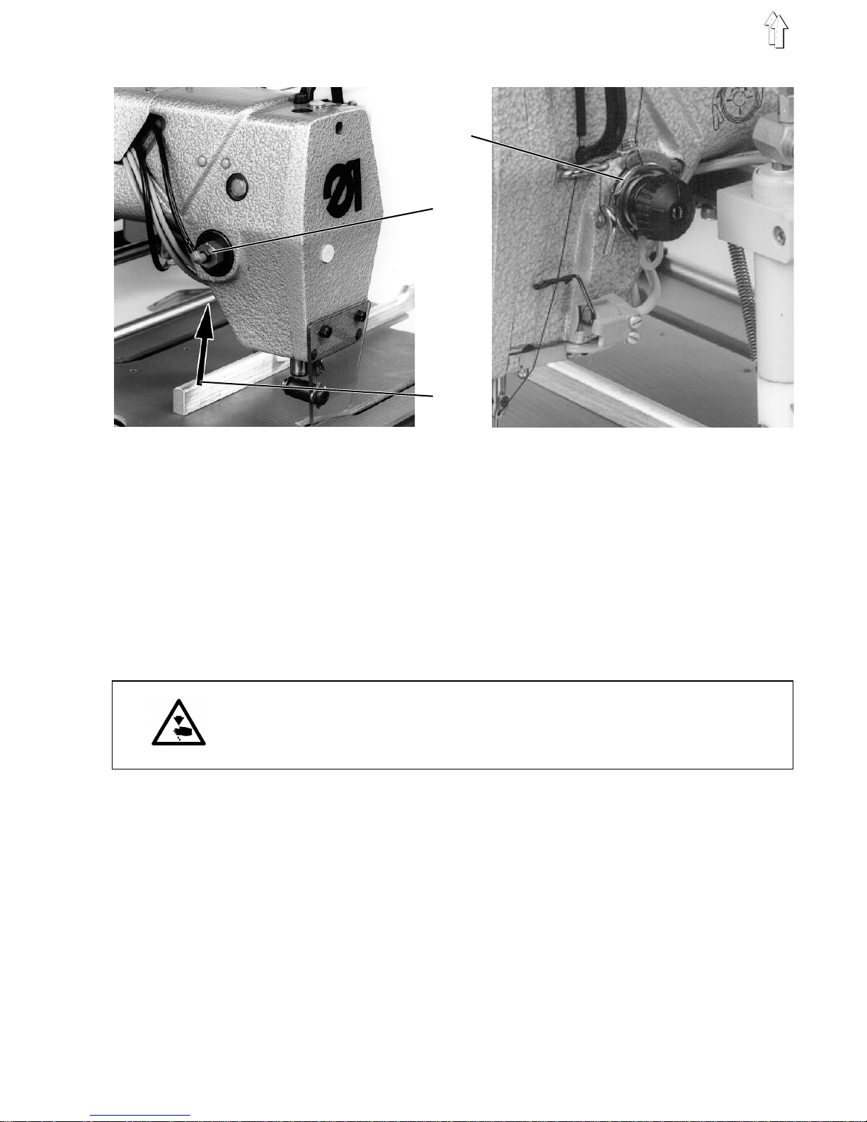
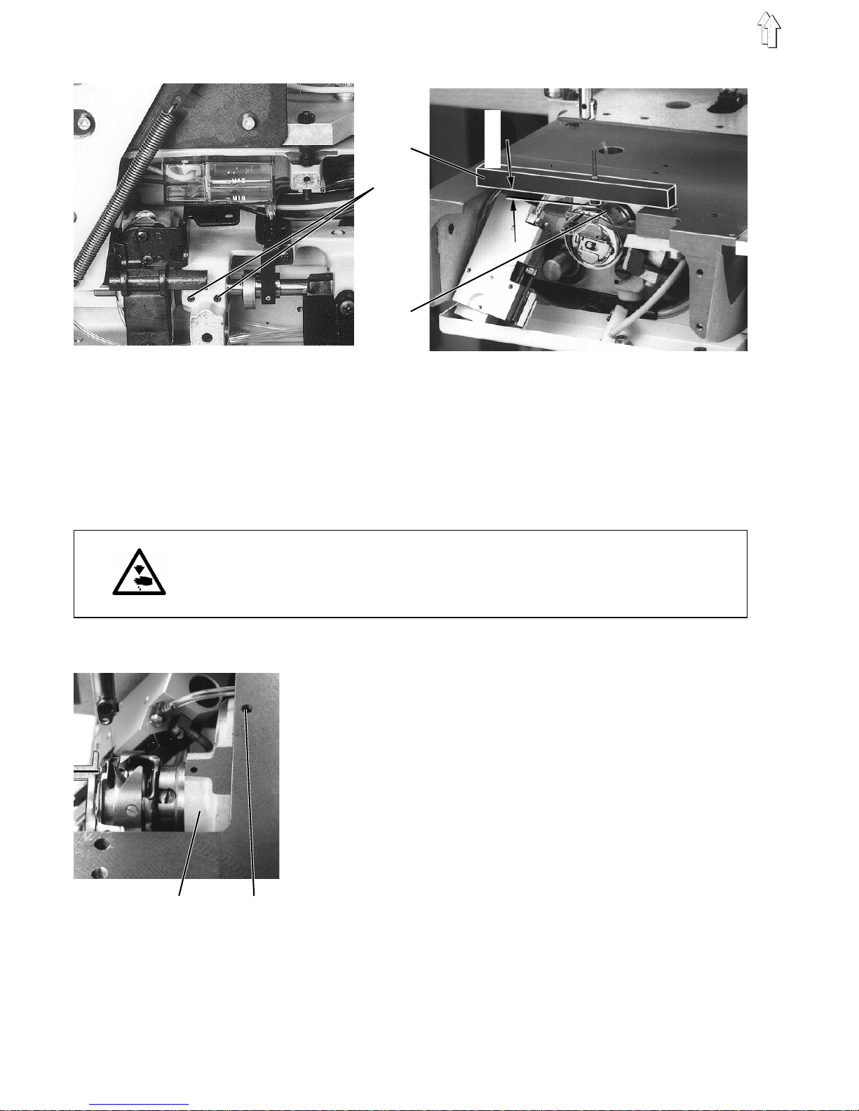
2.4 Upper-thread tensi oner release
Regulation and inspection
The cylinder 2 must open the tension discs 1 by about 1 mm.
When closed, the tension discs 1 must keep the upper thread securely
under tension.
–
Tur n the
"program"
switch to 64.
–
Press "STOP" button.
The program is activated.
–
Turn
"program"
switch to 24.
Switch on solenoid valve s24 by pressing the "Σ" button.
The upper-thread tensioner opens.
–
Check distance between tension discs 1.
Caution: danger of injury
Turn off the main switc h.
The upper-thread tensioner release may only be adjusted with the
motor-protection sw i tch tu rne d o ff.
Adjustment
–
Slightly un do screw 3.
–
Move cylinder 2.
With the upper -t hr e ad te ns i o ne r open there should be a distance
of 1 mm between the tension discs 1.
The distance c a n b e c h ec ke d with a gauge (s ee s ect i on 2.1 no. 3).
–
Retighten sc r e w 3 .
1
2
3
7
Page 8
2.5 Thread take-up spring
Regulation and inspection
The thread take-up spring 1 must keep the upper thread under tension
at least until the tip of the needle has penetrated the material.
Caution: danger of injury
Turn off the main switc h.
The thread take-up spring may only be adjusted with the sewing
machine swi tched off.
Adjusting the spring travel
–
Undo screw 4.
–
Rotate bush 3.
The spring 1 m us t pre-tension the up pe r th r ea d a t l e as t un ti l t he ti p
of the needle penetrates the ma te r i al.
–
Retighten screw 4.
Adjusting the spring tension
–
Undo screw 5.
–
Adjust the te ns i o n b y r ot at i ng te ns i o n b ol t 2.
Depending on the material and thread the tension of the thread
take-up spring must be between 20 and 30 cN (1 cN = 1 g).
The tension is me as u r ed at th read guide 6.
The thread is dr a wn pa r al le l to th e arm shaft.
–
Retighten screw 5.
3
4
5
1
2
20...30 cN
6
8
Page 9
2.6 Needle-bar hei ght
Regulation and inspection
Adjustment and inspection are carried out with gauge 1.
Caution: danger of injury
Turn off the main switc h.
The needle-bar h ei g ht ma y on l y be adjusted wit h t he s ew i ng ma c hi n e
switched off.
Adjustment
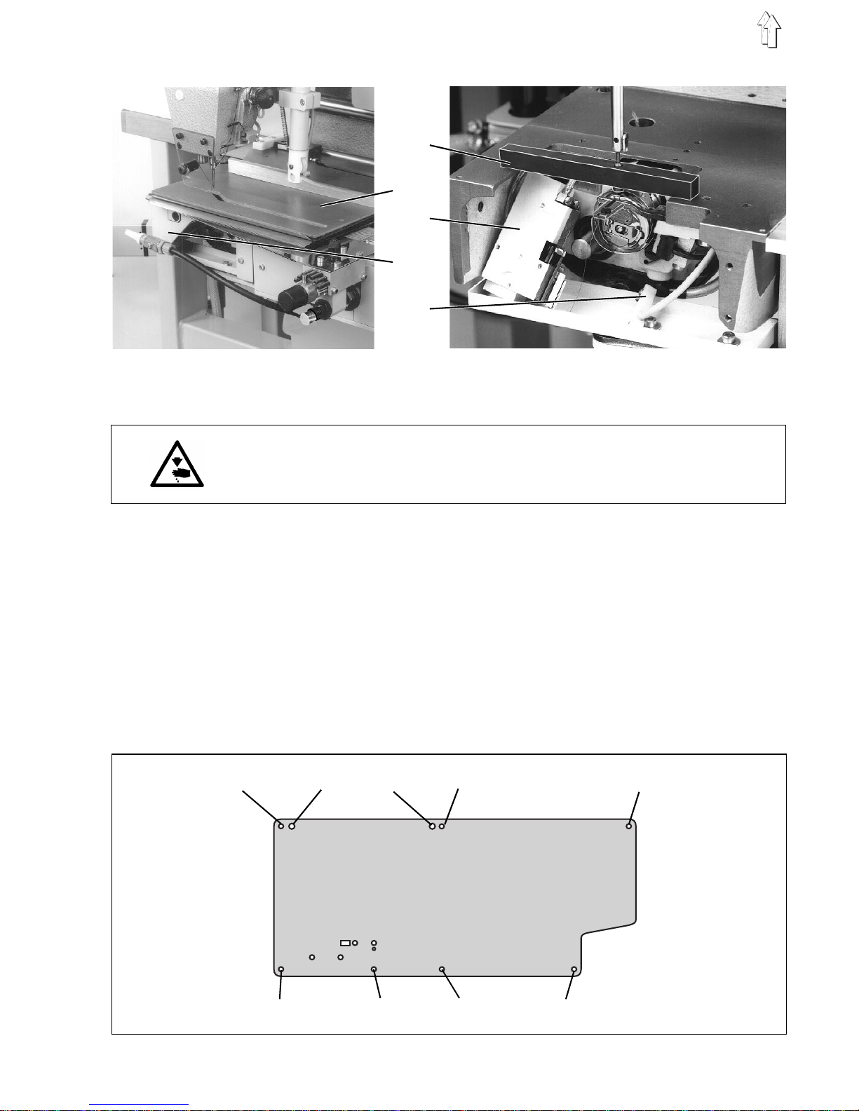
–
Remove shaping module 2.
–
Remove casing 4.
–
Undo light ba r r ier 5 an d t hr e ad c l ipp er 3 an d l a y th em on th e o i l
reservoir.
–
Undo screws 6 on th e s li d e p l at e a nd remove the sli d e p l at e.
IMPORTANT !
The centring screws 7 must not be rotated.
These are used to align the slide plate to the needle.
There are 2 shims between the sl i de pl a te an d t hr e ad c l ipper.
1
2
3
4
5
6 7 7 6 6
6 6 6 6
9
Page 10
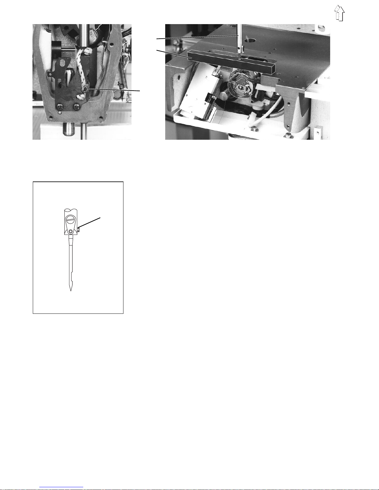
–
Place gauge 1 on th e b as e pl a te .
–
Unscrew safety shutter and head cover.
–
Undo clamping s cr e w 9 .
–
Lock the sewing machine in position E.
–
Lower the needl e ba r 8 o nt o t he ga ug e 1 .
The pin of gauge 1 must fully penetrate the needle bar.
–
Tighten needle-bar attachment screw 10.
The needle-at t a chm ent screw 10 must be aligned in pa ral l e l to th e
arm shaft and po i nt to th e r e ar ( t ow ar d s th e h an dw he el ) .
–
Replace all th e p art s wh i ch h av e be en rem ov e d.
IMPORTANT !
When fitting the thread clipper place both shims between the
thread clipper and slide plate.
10
8
1
9
10
Page 11
2.7 Shuttle settings
2.7.1 Loop lift and distance between shuttle beak and needle
Regulation and inspection
The loop lift i s t he tr a v el o f t he ne ed l e b ar from bottom dead c en tr e to
the point at which the shuttle beak is at the centre of the needle.
The loop lift is 1.8 mm.
–
Lock the machine in position A.
The shuttle b ea k 1 must be at the ce nt r e o f t he ne ed l e.
The distance b et w e en th e s h ut tl e be ak 1 an d t he ne ed l e m us t be
0.1 mm.
Caution: danger of injury
Turn off the main switc h.
The loop lift and the distance between the shuttle beak and needle
may only be ad jus t ed wi t h the sewing mac hi n e s w i tc h ed off.
Adjustment
–
Remove shaping module and slide plate (see section 2.6).
Fit new needl e.
–
Undo first a tt ac h me nt s c rew 3 of shuttle 4.
–
Lock sewing machine in position A.
–
Undo second a tt ac h me nt screw 3 of shuttle 4.
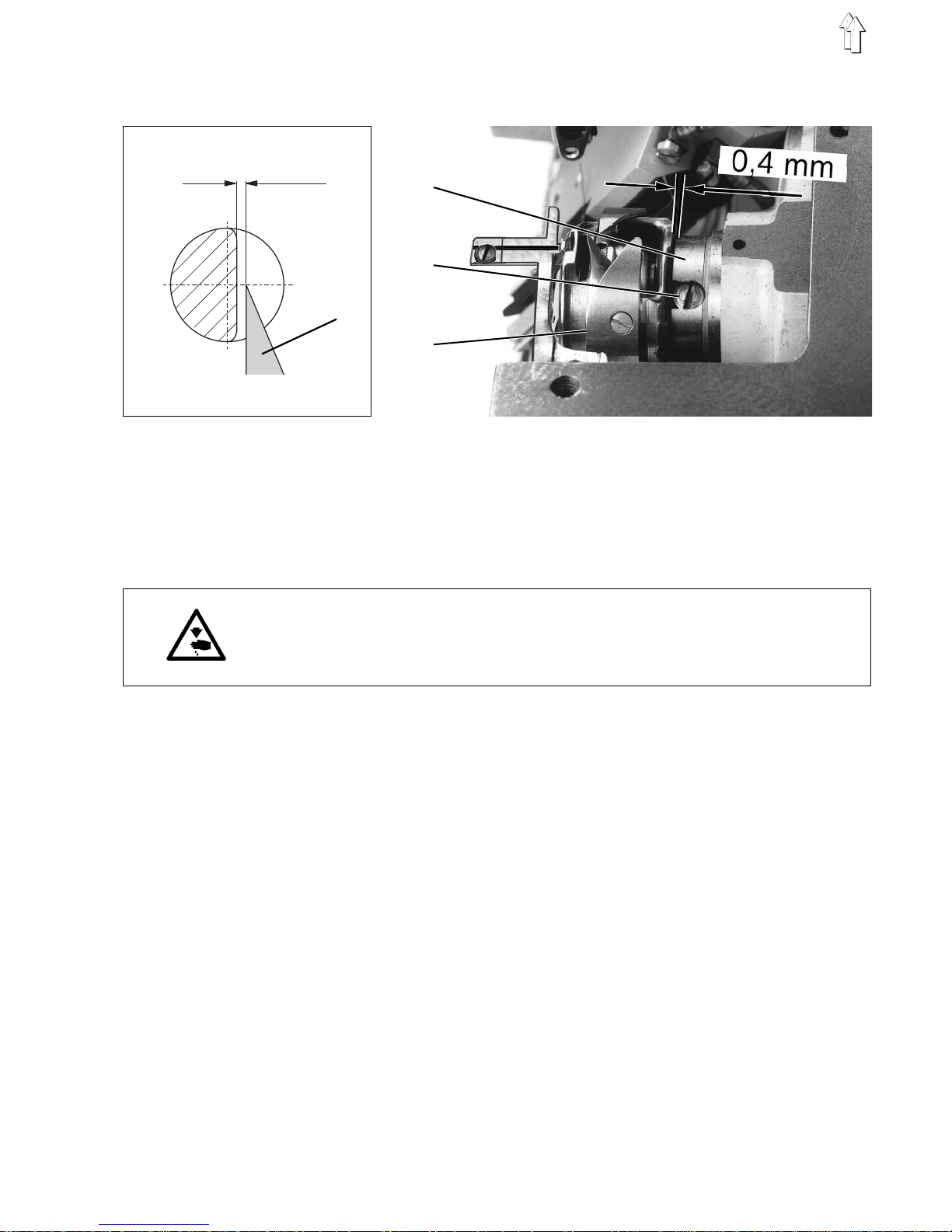
–
Place shut tle beak 1 at centre of ne ed l e.
The distance b et w e en th e s h ut tl e be ak 1 an d t he fu r row of the
needle must be 0. 1 m m.
In this position there is a distance of about 0.4 mm between the
shuttle 4 and t he bu s h 2 .
If the distanc e of 0. 4 m m i s n ot ac h i ev e d, th e s h ut tl e -dr i ve housing
should be adjusted accordingly (see section 7.2).
–
Retighten 2 at ta c hm en t s cr e ws 3 of th e s h ut tl e 4.
–
Replace all the parts which have been removed.
0,1 mm
1
2
3
4
11
Page 12
2.7.2 Shuttle-drive housing
Regulation and inspection
The shuttle-drive housing 4 is factory-aligned.
It may only be altered in exceptional circumstances.
With the shut tl e -dr i ve housing corr ectly aligned t he re m us t be a
distance of 0 .4 mm be tween the shuttl e a nd the adjusting ri n g
(see section 2. 7. 1) .
The distance b et w e en th e s l id e- p l at e s u rf a ce a nd the thread-dra wi n g
plate 3 is 3.8 mm.
Caution: danger of injury
Turn off the main switc h.
The shuttle-drive housing 4 may only be adjusted with the sewing
machine swi tched off.
Adjustment
–
Remove the sha pi n g m od ul e an d s l ide plate (see se c ti o n 2 .6 ) .
–
Unscrew locking screw 5.
Beneath the locking screw there is a stop screw.
–
Adjust stop screw.
The distance be tween the slide - pla t e sur f ac e an d t he
thread-drawin g p l at e 3 is 3. 8 m m
The distance is checked with gauge 1.
–
Retighten locking screw 5.
–
Undo screws 2 of the shuttle-drive housing.
–
Move shuttle -dr i ve housing 4.
There must be a distance of 0.4 mm between the shuttle and the
adjusting ring (see section 2.7.1).
–
Retighten screws 2 of the shuttle-drive housing.
–
Check the distance of the shuttle beak to the needle and adjust if
necessary (see section 2.7.1).
3,8 mm
1
2
3
4 5
12
Page 13

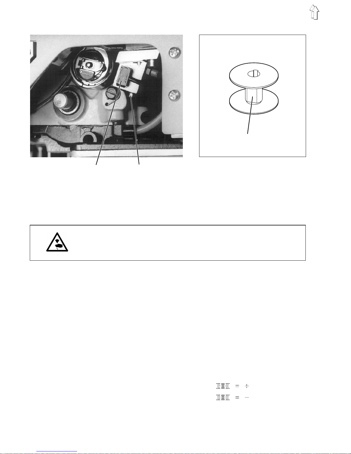
2.8 Bobbin-housing holder
Regulation and inspection
The bobbin-hou s i ng ho l de r is fa c to r y- al i g ne d.
After the hol de r ha s be en replaced it ma y be ne c es sary to re-align th e
new one.
The spring wire 1 must be in close contact with the bobbin-housing
holder with no gaps.
Half the width of the spring wire 1 m us t be ove r th e re ta i ni n g t ab 3.
Caution: danger of injury
Turn off the main switc h.
The bobbin-hou s i ng ho l de r ma y on l y be ad j us t ed wi t h t he s ew i ng
machine swi tched off.
IMPORTANT !
Alignment ma y on l y be c ar ri e d o ut i n t he cross-hatche d a r ea 5
(see sketch).
The extreme har d ne s s i n t he region of the re taining tab 3 mea ns t ha t
there is a danger of breakage th er e .
Adjustment
–
Align the bo bb i n-housing holde r 6.
The distance b et w e en th e r e ta i nin g tab 3 of the bobb i n-h ou s i ng
holder 5 and the lower part of the bobbin housing 4 must be
0.6
+0.1
mm.
–
Undo screw 2.
–
Move the wire so th at i t i s i n c los e c on ta ct with the retainin g t ab or
is 0.1 mm away from it.
–
Tighten screw 2.
Note
If the holding wire 1 is worn it can be reversed and the other end used.
2
3
4
5
6
1 3
1
13
Page 14
2.9 Light bar rier of residual -thread monitor
Regulation and inspection
If the light barrier is properly aligned a reflection occurs when an
empty bobbin i s ro ta te d.
The alignment of the light barrier is carried out in program 42.
Caution: danger of injury
Turn off the motor safety switch .
The reflex light barrier may only be aligned with the motor safety
switch turned off.
IMPORTANT !
The residual-thread monitor is only operational if the value for the
shuttle-thread counter in program 41 has been set to
0000
.
Checking the alignment
–
Place an empt y bo bb i n o n t he s l ee ve ( g au ge 5, s ec t i on 2. 1) a nd
insert it in the bobbin housing.
–
Move the shutt l e b y tu rni n g the handwheel un ti l t he i nf r a-r e d
radiation of the light barrier 1 can fall on the bobbin hub through
the light aperture in the bobbin housing (shuttle beak down).
–
Set "
program
" switch to 42.
–
Press "
STOP
" button.
The program i s act i v at ed .
–
Rotate empty bo bb in with the sleeve (ga ug e 5 ).
If the infrared radiation from light barrier 1 falls on the reflective
surface 3 of the bobbin hub, this must appear in the display:
display with reflection:
display with no reflection:
12
3
14
Page 15

Adjusting the alignment
–
Clean the lenses of the light barrier 1 and the reflection surface 3
of the bobbin hu b with a soft cl ot h.
–
Undo clamping screw 2.
–
Press the light barrier 1 into the light-barrier holders as far as it will
go.
–
Gently tighten clamping screw 2.
–
Align light barrier.
Rotate light barrier 1 until
appears in the display.
–
Re-tighten clamping screw 2.
–
Check alig nm en t a ft er cl a mp i ng an d r e - ad j ust i f n ec e s s ary.
2.10 Bobbin winder
Regulation and inspection
The bobbin wi nd er s h ou l d a ut omatically tur n off wh en th e b obbin is
fully wound t o a po i nt ab ou t 0 .5 mm under the rim.
Caution: danger of injury
Turn off the main switc h.
The bobbin winder may only be adjusted with the sewing machine
switched off.
Adjustment
1. Minor adjustments to the wind-on quantity
–
Bend bobbin- w i nd er flap 3.
2. Major adjustments to the wind-on quantity
–
Remove bobbin-winder cover.
–
Undo screw 2.
–
Rotate trip cam 1:
in the direction of arrow A: to reduc e th e w i nd - on qu an ti t y
in the direction of arrow B: to incre as e th e wind-on quanti t y.
–
Retighten sc r e w 2 .
–
Replace bobb i n- w i nd er c o v er.
3
1
2
A
B
15
Page 16

2.1 1 Position sensor
Regulation and inspection
After sewing the upper part o f t he ma c hi n e m us t mo v e t o p os ition C of
the adjusting disc.
Caution: danger of injury
Turn off the main switc h.
The light apertures may only be adjusted with the main switch turned
off.
–
Partly undo c l am pi n g s cr e w 6 .
–
Rotate light apertures 1 and 4 so that their light slits 2 and 5 are
opposite each other (offset by 180°).
The position of light apertu re 4 al s o de te r mines the moment at
which the thread clipper switches on.
–
Tighten clamping s cr ew 6.
IMPORTANT !
The light apertures 1 and 4 must not be rotated when tightening the
clamping screw 6.
–
Turn on the main swit c h.
–
Set the "
program
" switch on th e f r on t p l at e o f t he c on tr o l de vi c e t o
a sewing pro gra m (
" 10...29 ")
.
–
Press the "
P
" button for 3 seconds.
Set the motor-speed parameter to maximum.
–
Place the mat eri a l i n p os i t i on an d s t art the sewing proce s s .
IMPORTANT !
Never start u p with no materi al i n pl a c e: th i s ma y da ma ge th e
material clamps.
–
After the thread is cut the upper part of the machine moves to the
second needle position (position C).
4
5
6
1
2
3
7
8
16
Page 17

–
Check the ex ac t sec o nd ne edle position C with the loc k i ng pin.
–
If the locking pin will not go into notch C of the adjusting disc,
correct the second needle position.
Adjustment
–
Undo both clamping screws 7 on the position-sensor ring 8.
–
Hold position-sensor ring 8 steady and rotate handwheel.
–
Fully tighten clamping screws 7.
–
Carry out sewing process.
–
Check the second needle position with the locking pin.
–
If necessary, correct the position of the position-sensor ring 8
again.
17
Page 18

2.12 Replacing the right-hand arm-shaft bearing
Regulation and inspection
The right-hand arm-shaft bearing must be replaced if the arm shaft
does not run smoothly.
Caution: danger of injury
Turn off the main switc h.
The arm-shaft bearing may only be replaced with the sewing machine
switched off.
IMPORTANT !
Do not use an extractor tool.
When the right-hand arm-shaft bearing is removed and replaced no
axial press ure mu s t b e ex e r te d on the arm s ha ft. Axial pressur e in the
direction of the head cover will damage the thread lever.
Replacing the arm-shaft bearing
–
Remove position sensor, handwheel, arm and head covers.
–
Unfasten the belt protector and remove it together with the belt.
–
Remove the 2 reta i nin g s p ri ng s 1.
–
Undo screws 2 a nd 6.
–
Carefully prise off the V-belt pulley with 2 screwdrivers or similar.
–
Remove the ball-race 4 with the extractor tool and remove circlip 5.
–
Fit the circli p t o t he ne w b al l- ra c e (o r de r no .: 02 11 000361) and
carefully press the complete unit onto the V-belt pulley.
–
Gently tap the V-belt pulley into place with a synthetic hammer.
–
Replace in reve r se o r de r th e p arts which have be en rem ove d.
2 3
4 5 6
1
18
Page 19

2.13 Lubrication
The oil passes from the oil reservoir 5 to the sump 1, from where the
lubrication s po i nt s in the arm and sewi n g-h ea d r e gi o ns a re s u pp l i ed
with oil.
The oil thrown off by t he c ran k me cha ni sm pa s s es a l on g t he wi ck 2 to
the central distributor pipe 4 for the lubrication points located under
the base plate. Excess oil drips into the oil-collection tray 6 and is
returned to th e su mp 1 by the pump 3.
This provides effective lubrication with minimum oil consumption.
Caution: danger of injury
Turn off the main switc h.
Work on the oil-circulation system may only be carried out with the
sewing machi n e switched off.
IMPORTANT !
After work is completed it is essential to ensure that the hoses are
correctly reconnected to the pump.
S = suction
D = pressure
Regulation and inspection
The oil level must be checked every week.
–
Check the oil level at the oil reservoir 5.
The oil level m ust be be tween the MIN and MA X m ark s.
If necessary top up the oil to the MAX mark.
1
2
3
4
5
6
19
Page 20

2.13.1 Shuttle lubrication
Caution: danger of injury
If shuttle lubrication is checked with the sewing machine switched on,
the utmost care must be taken.
Oil can cause skin rashes.
Avoid protracted contact with the skin.
In the event of c o nt ac t , t horoughly wash t he aff ect ed area.
Turn off the main switc h.
Shuttle lubrication may only be adjusted with the sewing machine
switched off.
IMPORTANT !
The handling and disposal of mineral oils is subject to legal
regulations.
Used oil must be delivered to an authorised acceptance point.
Protect the e nvi r o nm en t.
Take care that no oil is spilled.
Regulation and inspection
The oil quantity r e qu ir ed fo r s hu tt l e lu br ic a ti o n va r i es with the sewing
yarns and mater i a l to be processed.
A piece of paper - ideally blotting paper - held beneath the shuttle
should be lightly sprayed with oil when 8-10 stitches are sewn.
Adjustment
–
Adjust screw 2:
anti-clockwise = more oil
clockwise = less oil
1 = shuttle-lubrication oil reservoir
1
2
20
Page 21

3. Adjusting the sewing machine
3.1 Thread clipper
Regulation and inspection
When the thread is being cut the moving blade must be able to move
freely in the s l i t of th e s h ap i ng mo du l e.
Caution: danger of injury
Turn off the main switc h.
The thread clip pe r ma y on l y be r em ove d w i th th e s e win g m ac h i ne
switched off.
Removing the thread clipper
–
Remove shapi n g m od ul e an d c a s i ng 1.
–
Remove screws 2 and 4.
IMPORTANT !
Between the slide plate and thread clipper there are 2 shims.
–
Mark 3 hoses on the thread clipper 7 and then unscrew them.
–
Remove the thread clipper 7.
Fitting the thread clipper
–
Connect the hoses to the correct connections.
–
Attach the thread clipper 7 under the slide plate 3.
Make sure the hoses cannot be fo ul e d b y moving parts.
–
Attach screws 2 and 4.
When the thread is being cut the moving blade must be able to
move freely in the slit of the shaping module.
IMPORTANT !
When fitting the thread clipper place the shims between the slide
plate and thre ad c l ipper.
–
Replace cas in g 1 and shaping mo du l e.
Function-testing the thread clipper
–
The function of the thread clipper 7 can be checked with
program 64 (se e b ri ef de s c ri pt i on of Microcontro l) .
2 3 4 5 6
1
7
21
Page 22

3.1.1 Fitting and removing the blades
The blades mus t b e r e pl a c ed an d a dj u s te d w i th th e t hr e ad c l ipp er
removed. The thr ea d m ust be r eli a bl y s e v ere d wi t h th e mi n imu m
possible pre s sur e .
Regulation and inspection
The distance from the edge of the fixed blade 12 to the surface of the
body of the clipper is 1.5 mm.
The edge of the moving blade is just beneath that of the fixed blade.
This is the case if the distance from the edge of the blade to the
surface of th e b od y of the clipper i s 2 m m.
Caution: danger of injury
Turn off the main switc h.
The thread clip pe r ma y on l y be r em ove d w i th th e s e win g m ac h i ne
switched off.
Blades may onl y b e f i tt ed an d r e mo v ed wh en th e t hr e ad c l i pp er h as
been removed.
Removing the blades
–
Remove thread clipper (see section 3.1).
–
Remove screws 3 and 5.
Remove cover plate 1 and blade-guide plate 6.
IMPORTANT !
Do not lose the pressure spring 4.
–
Remove moving blade 2
downwards
from the blad e-guide plate 6.
This is nec ess a r y to ensure that the b l ad e i s n ot damaged.
–
Undo screws 15 an d 1 7.
Remove the pressure plate 16.
–
Remove blade 12 ( f ix ed bl a de ).
Position ma rk i ng s
S28, S30
and
S31
(compressed -ai r c o nn ec t i on s )
denote the res pe c tiv e s ol e no i d valves.
1
2
3
4
5
S31
S28
S30 6
17
22
Page 23

Fitting the blade
–
Screw the bla de 12 on to th e p res su r e p lat e 1 6.
The distance from the edge of the blade to the surface of the body
of the clippe r i s 1. 5 m m.
–
Tighten screws 15 an d 1 7.
–
Undo pressure screw 13.
–
Fit the moving blade 2
from below
into the blade-guide plate 6.
Check that the blade moves freely.
–
Tighten the pressure screw 13 and adjust for Cutting pressure.
The sewing threads must be reliably severed with the minimum
possible pre s sur e .
Carry out a cutti n g t es t (s ee als o s ect i on on fu nc t ion te s ti n g).
The lower end of screw 13 is split. It may be slightly expanded for
a secure fit.
–
Fit blade-guide plate 6.
The collar 18 mu s t e ng ag e w i th th e c y l in der 8.
Pin 10 must enga ge wi t h t he ho l e 14.
Pin 9 must engage with the slot of the moving blade 2.
–
Fit the cover p l at e 1 wi t h p r ess u r e sp r i ng 4 o nt o t he bl a de - gu i de
plate 6.
–
Fully tighten screws 3 and 5.
Adjusting the height of the moving blade 2
–
The height of th e m ov i n g b l ad e 2 i s adjusted with s cr e w 11.
If this screw 11 has been uns cr ew ed i t m us t be r ep l aced in the
hole together with Teflon tape and screwed in to its previous
position.
The setting of the moving blade 2 must be such that its edge is just
beneath the ed ge of th e f i x ed bl a de 12 . T h is i s th e c ase if the
distance from the edge of the blade to the surface of the body of
the clipper i s 2 m m.
15 16 17 2 18
7
12
13
14
89 1011
2 12
23
Page 24

3.1.2 Replacing the piston
The moving blade is raised pneumatically.
The piston 4, wh i ch o pe r at es t he bl a de , i s l o cated in the body o f t he
clipper.
Regulation and inspection
When the piston is replaced it must be adjusted so that the edge of the
moving blade i s j us t be ne at h the edge of the f i xed bl a de 12 .
Caution: danger of injury
Turn off the main switc h.
The thread clip pe r ma y on l y be r em ove d w i th th e s e win g m ac h i ne
switched off.
The piston ma y on l y be r ep lac e d when the thread c l i p pe r ha s be en
removed.
IMPORTANT !
The surface of th e h ol e i s an od i sed.
When replacing the piston take care not to damage the anodised layer.
Adjustment
–
Remove thread clipper (see section 3.1).
–
Remove retaining ring 1.
IMPORTANT !
Washer 2 is under spring pressure.
–
Remove washer 2 , p res s u r e sp r i ng 3 a nd pi s t on 4 w i th O -r i ng 5.
–
Grease the surf ace of th e h ol e wi t h
ESSO S420
grease.
(Order no.: 0791 000304)
–
Re-assemble the pi s t on in t he r eve r se o r de r.
If this screw 11 has been unscrewed it must be replaced in the hole
together with Teflon tape (see section 3. 1. 1) .
–
Fit the thread clip pe r.
–
Carry out a cutting test with sewing threads (test program).
6
7
1 2 3 4 5 6 7
24
Page 25

3.2 Folding table
Regulation and inspection
Depending on th e thickness of t he ma te r i al t he fo l di n g p l at e 1 s ho ul d
be in parallel with the slide plate at a height of between 1 and 1.5 mm
above it. The height is determined by the thickness of the material.
In the 0 position the leading edge of the folding plate 1 runs parallel to
that of the sli d e p l at e.
The insertio n d ep th i s de te rmi n ed by t he material. The firs t
penetration o f t he ne ed l e i n to th e m aterial should be as c lose as
possible to th e fold-over edge .
Caution: danger of injury
Turn off the main switc h.
The folding table may only be adjusted with the sewing machine
switched off.
Adjustment
1. Adjusting the height
–
Unscrew screws 2 and 6.
–
Adjust the height of the folding plate 1 by inserting or removing
separators (contained in the accessory kit) between the block 8
and the foldin g p l at e 1 .
–
Tighten screws 2 and 6.
2. Adjusting the position
–
Move the swi v el arm to the 0° position.
–
Undo screws 2 and 6 and the clamping lever 5.
–
Align the folding plate 1 in parallel with the slide plate.
The leading edge of the folding plate should be above the centre of
the needle hol e a nd th e 0 ° edge of the sc a l e.
The depth setting must be adjusted if necessary.
–
Retighten sc r e ws 2 an d 6 an d c l a mp i ng lev e r 5.
3. Adjusting the insertion depth
–
Undo locknut 9.
–
Adjust the depth setting 4.
With medium-h eavy material t he fi rs t pe netration of the ne ed l e i n to
the material sho ul d be as c l o s e a s po s s i bl e to th e f ol d -ov e r ed ge .
–
Retighten lo c k nu t 9 .
5
6
7
8
9
1
2
3
4
25
Page 26

3.2.1 Retraction of folding table
The folding t ab l e is e x te nd ed by a pn eu ma ti c c yl i n de r an d re tr a c te d b y
a tension spring.
Regulation and inspection
The tension in th e s p r i ng mu st b e su c h t ha t w i th th e f ol d i ng ta bl e
retracted the l e v er li e s pa r all e l to th e e dge of the base pl at e.
The extension movement of the folding table must be rapid, but not
instantaneous.
Caution: danger of injury
Turn off the main switc h.
The retracti on of th e f ol d i ng ta bl e ma y on l y be adjusted wit h t he
sewing machi n e switched off.
Adjustment work and function testing with the sewing machine running
must be carri ed ou t w i th th e u tmost care.
Adjustment
1. Adjusting the retraction of folding table
–
Push the folding table in.
–
Remove the right-hand casing and detach the tension spring 4.
–
Undo screw 2.
–
Press the pre s sur e rol l e r 6 o nt o t he c on tr o l cam 7, at the same
time aligni n g t he l ev e r 3 i n pa r al le l wi t h t he edge 1 of the ba se
plate and tighten screw 2.
The axial play in the shaft must not exceed 0.5 mm.
–
Re-attach the te ns io n s p r ing 4.
2. Adjusting the extension speed
–
Adjust the extension speed of the folding table at the throttle valve.
The movement s ho uld be rapid, but n ot i ns t an ta ne ou s .
The throttle valve can be reached through hole 5.
1
2
3
4
5
67
26
Page 27

3.2.2 Angle adjustment, switch point b03
The angle is ad j us t ed ma nu al l y. The manual g r ip i s co mp res s e d an d
the angle adjusted in accordance with the scale.
Regulation and inspection
The angle set mu st be kept consta nt wi t h t he br a ke.
When the table is in the forward position the proximity switch
b03
must
operate.
Caution: danger of injury
Turn off the main switc h.
The angle adj ust ment may only be ad j usted with the sew i ng ma c hi n e
switched off.
Adjustment work and function testing with the sewing machine running
must be carri ed ou t w i th th e u tmost care.
Adjustment
1. Angle adjustmen t
–
Tighten 2 screws 1.
The manual gri p 6 mu s t p r ess u ni f or m l y on the pressure p l at e 2 .
The distance of the manual grip 6 to the base plate 7 is about
5 mm on the oute r ed ge .
–
Tighten locknuts 3.
2. Adjusting the switch point for b03
–
Adjust switch with program 63.
–
Undo locknut 5.
–
Rotate the index ring 4 until the proximity switch
b03
operates
securely (see display).
–
Tighten locknut 5.
b03
4
5
6
7
1
2
3
5 mm
27
Page 28

3.3 Transport carr iage
The transport carriage holds the shaping module and moves it in
accordance with the seam pattern.
Regulation and inspection
The transport carriage must be at an angle of 90° to the arm shaft.
The reference point must be adjusted with the gauge.
Caution: danger of injury
Turn off the main switc h.
The transport c arr iage may only be ad j ust ed with the sewi ng ma c hi n e
switched off.
Adjustment work and function testing with the sewing machine running
must be carri ed ou t w i th th e u tmost care.
Adjustment
–
Remove the sha pi n g m od ul e an d s l ide plate (see se c ti o n 2 .5 ) .
–
Place the gauge 5 (order no. 0935 107077) on the base plate of
the sewing machine and attach it with screw 3.
–
Undo 2 screws 1.
–
Align the transport carriag e with the gauge.
The shaft 2 must be in contact with the gauge.
–
Tighten 2 screws 1.
–
Align the st op pl a te 4 a t a bo ut 5° (anti-cl ock w i s e) to the surface 11
of the gauge 5 .
–
Move the transport carriage about 100 mm to the left.
–
Select program 01 (sewing program) and turn on the main switch.
When the dis pl a y
" <--- REF ---> "
or
" REF ---> "
appears press
the " Σ " button.
The transpor t c a rr i ag e m oves to the referen c e p os i t i on .
The position of the stop plate 4 i s a l te red by t he pi n 6. In this
position th e s t op pl a te 4 m us t be i n c lo s e c o nt ac t wi t h t he ed ge 11
of the gauge.
–
If it is not, undo screws 7 and adjust the switch plate 10.
–
Check position i ng ag ai n .
–
Adjust stop screw 8 and secure with locknut 9.
The distance between the support and the screw head is
about 1 mm.
1
2
3
4
5
6
78 910
11 4
8
1 mm
28
Page 29

3.3.1 Overrun protection
Regulation and inspection
Overrun protec t i on on th e l e ft of the transport c a r ri ag e i s p rov i d ed by
proximity switch
b05
.
Caution: danger of injury
Turn off the main switc h.
Overrun protec t i on ma y on l y be ad j usted with the sew i ng ma c hi n e
switched off.
Adjustment work and function testing with the sewing machine running
must be carri ed ou t w i th th e u tmost care.
Adjustment
–
Adjust the height of proximity switch
b05
so that the switch plate 3
can pass through without a gap.
If this is not t he cas e , b en d t he ta b 2 .
–
Push the transport carriage manually to its left-hand end position.
–
Select progr a m 62 and turn on the main switch.
Press
"STOP"
button.
Set the
"program"
switch to 05.
–
Push the switch plate 3 towards the proximity switch until this
operates secu r el y.
Bend the lugs of th e p l at e i n to th e n earest tooth gap s .
–
Undo 2 screws 1.
–
Move tab 2.
This carries o ut th e f i ne ad j us t me nt of th e s w i tc h po i nt .
–
Retighten 2 sc r ew s 1.
–
Check the switch function.
1
2
b05
3
29
Page 30

3.4 Shaping modul e
3.4.1 Shaping-module guide roller
Regulation and inspection
The position of the guide roller 4 is adjusted with gauges 5 and 6.
The pneumatic cylinder 8 is only needed for seams with a small radius
of curvature.
Caution: danger of injury
Turn off the main switc h.
The guide roll e r may only be adjus t ed wi t h the sewing mac hi n e
switched off.
Adjustment
–
Remove the sha pi n g m od ul e an d s l ide plate (see se c ti o n 2 .6 ) .
–
Place gauge 5 (or d er n o. 09 35 10 70 77 ) on th e b as e pl a te of th e
sewing machine and attach it with screw 3.
–
Pivot the upper part of the machine to the left.
–
Undo adjusting ri ng s 1 a nd 3.
Move the shaft 2 until the guide roller 4 is at a distance of 1 mm
from the firs t s u r fa ce of the gauge 5.
Check the distance with gauge 6 (order no. 0933 080200).
–
Re-attach adjusting rings 1 and 3.
–
Undo the locknu t a nd un sc r ew sc r ew 7 a fe w t urn s .
–
Screw 9 press e s on the piston ro d.
Turn screw 9 until the guide roller 4 is at a distance of 1 mm from
the second surface of the gauge 5.
Check the distance with gauge 6.
–
Tighten locknut onto screw 9.
–
Screw in screw 7 as far as it will go and lock it.
–
Use gauge 6 to c he c k that the guide ro l l er i s a t a di stance of 1 mm
from both surf ac e s of th e g au ge 5.
If it is not, repeat the process.
1
2
3
4
5
6
789
46
30
Page 31

3.4.2 Shaping-module pressure cylinder
Regulation and inspection
The pressure c y l inder 3 closes th e s h ap i ng mo du l e.
The clamping frame 1 is supported on a shaft. The pressure cylinder 3
is free to swing. The return movement is carried out by the spring
plate 7. When the shaping module is fitted the roller bracket is
opposite the c o nt rol c a m 6 .
Caution: danger of injury
Turn off the main switc h.
The pressure cylinder may only be adjusted with the sewing machine
switched off.
Adjustment
1. Adjusting the height.
–
Turn the handwheel un ti l t he ne ed l e i s a t t op de ad c en tr e .
–
Move the shap i ng mo du l e. T he gu i de rol l e r 5 of the pressure
cylinder 3 must press on the curve of control cam 6.
–
Undo screw 2 an d m ov e th e p r ess u r e cy l i n de r 3 in the clamping
frame 1.
The distance between the tip of the needle and the upper side of
the shaping mo du l e i s 2.5 mm. The inne r s ur f ac e s 4 of the roller
bracket must be parallel to the control cam 6.
–
Retighten sc r e w 2 .
2. Adjusting the spring plate 5.
–
Undo clamping screw 8.
–
Move the spri ng pl a te 7 a l on g the shaft.
5 mm of the spri n g p l at e m us t be i n contact with the c l am pi n g
frame.
The guide roll e r 5 i s a bo v e t he c en tr e of th e c o nt r ol c a m.
–
Retighten cl a mp i ng s c rew 8.
IMPORTANT !
The slide surface of the spri ng pl a te 7 must always b e ke pt greased.
1
2
3
4
5
6
78
31
Page 32

3.4.3 Shaping-module closing movement
Regulation and inspection
The closing m ov e me nt fo r th e shaping module i s d et erm i ne d b y th e
throttle and t he c l osi n g force by the pre s sur e r eg ul a to r.
The closing m ov e me nt of th e p r es su r e c yl i n de r mu s t b e ra pi d , but not
instantaneou s .
The material m us t be pr o pe rl y transferred with th e minimum possi bl e
pressure.
Caution: danger of injury
Adjustment work and function testing with the sewing machine running
must be carri ed ou t w i th th e u tmost care.
Adjustment
1. Adjusting the closing movement
–
Adjust the throttle 1.
2. Adjusting the closing force
–
Activate pro gr a m 6 4 (s e l ec t ou tp ut el e me nt s ) .
Press
"STOP"
button and set
"program"
switch to 32.
–
Check that the ma te r ial i s p rop erl y t ran s fe rr ed .
Place the thinnest material in position and push in the folding
table. Press the "Σ" button. The cylinder is operated.
Check that the material is securely held.
–
Adjust the pressure regulator:
to increase pressure: screw in tap screw 2
to decrease pressure: unscrew tap screw 2
The material must be properly transferred with the minimum
possible pressure.
IMPORTANT !
If the pressure is insufficient the pressure cylinder is not vented.
1
2
32
Page 33

3.4.4 Adjusting the shaping module
The sewing mac hin e c a n b e f i tt ed wit h v a ri ou s sha pi n g m od ul e s fo r
different seam patterns.
See section 2. 12 of th e O p era t in g manual.
Regulation and inspection
The shaping module must be mounted on the support shaft with no
play.
The material clamps must be fitted so that the adjusting pins
(gauge 1, section 2.1) can be inserted through holes 4.
The pressure of the folding r ims ( p re- t en s i on of th e m at er i a l cl am ps ) is
determined by the curvature of the shaping module.
Caution: danger of injury
Turn off the main switc h.
Remove the shaping module from the sewing machine and adjust it.
Adjustment
1. Adjusting the holding claws
–
Undo the attachment screws 2 of the holding claws 1.
–
The shaping module must be mo un te d o n the support shaft with no
play.
Otherwise adjust the position of holding claws 1 and 6.
–
Retighten a tt ac h me nt s cr ew s 2.
2. Adjusting the position of the material clamps
–
Compress th e sh aping module (t o t he s am e d i me nsi o ns a s i n t he
sewing machi n e).
It must be possible to pass the adjusting pins through the holes 4.
If it is not, undo the screws 3 and adjust the plates accordingly.
3. Adjusting the pressure of the folding rims
–
Bend the mater i a l cl am ps t o t he correct curv at ur e .
Standard set ti n g: 2. 5 m m.
The distance m us t be th e s a me al o ng th e e ntire length of th e
material clamp. The distance must also be the same for both
plates.
4. Using the shaping module on the 743-121 sewing machine
–
The shaping modules of the
743-221
do not have stop 7.
If the shaping mo du l e i s t o b e u s ed on th e
743-121
, fit stop 7 into
slot 5 with nu t 6 .
The stop must be ad j ust ed. See the
743-121
service manu al .
1
2
3
4
5
2,5 mm
7
6
33
Page 34

4. Maintenance unit
The maintenan c e u ni t pro tects the sewi ng ma c hin e from water and
particles of di rt in order to avo i d b l oc ka ge s an d r u s t f ormation in the
pneumatic system.
Regulation and inspection
The water level in the pressure regulator must not reach the filter.
The filter in s ert 1 m us t be c l ea ne d e v er y 1 60 hours.
Caution: danger of injury
Turn off the main switc h.
Isolate the s ew i ng ma c hi n e f r om th e compressed-ai r s up pl y.
The filter may only be cleaned when the system has been
depressurised.
–
Blow the water out of the water separator under pressure.
–
Wash the filter holder and filter insert 1 with petroleum ether.
Blow the filter insert 1 clean with the compressed-air gun.
Important !
Do not use solv en ts t o wash the filter ho lde r an d f il te r ins e rt.
They destroy th e f i l te r ho l de r.
1
34
Page 35

5. Maintenance
Caution: danger of injury
Turn off the main switc h.
Maintenance of the sewing machine may only be carried out when it is
switched off.
The maintenance work to be carried out daily or weekly by the sewing
machine’s opera ti n g p er s o nn el (c l e an i ng an d l u bri c a ti o n) i s d es c ri b ed
in part 1: Ope rat i ng ma nu al . It is given in th e f ol l o wi n g t ab l e f or t he
sake of completeness.
Work to be carried out operating hours
8 40 160 500
upper part of machine
clean up dust , l in t and thread frag me nt s in the region of th e s h ut tl e an d
needle plate . . . . . . . . . . . . . . . . . . . . . . . . . . . . . . . . . . . . X
clean light barrier . . . . . . . . . . . . . . . . . . . . . . . . . . . . . . . . . X
check oil level in reservoir . . . . . . . . . . . . . . . . . . . . . . . . . . . . X
check oil level in shuttle-lubrication reservoir . . . . . . . . . . . . . . . . . X
check shuttle lubrication . . . . . . . . . . . . . . . . . . . . . . . . . . . . . X
clean lenses of residual-thread monitor . . . . . . . . . . . . . . . . . . . . X
check cogged belt . . . . . . . . . . . . . . . . . . . . . . . . . . . . . . . . X
sewing machine
clean motor-fan screen . . . . . . . . . . . . . . . . . . . . . . . . . . . . . X
check condition and tension of V-belt . . . . . . . . . . . . . . . . . . . . . . X
clean filter for stepping-motor drive . . . . . . . . . . . . . . . . . . . . . . . X
inspect condition and tension of transfer-carriage V-belt . . . . . . . . . . . X
lubricate laminated spring on pressure cylinder . . . . . . . . . . . . . . . . X
pneumatic system
check water level in pressure regulator . . . . . . . . . . . . . . . . . . . . X
clean filter insert in maintenance unit . . . . . . . . . . . . . . . . . . . . . . X
check system impermeability . . . . . . . . . . . . . . . . . . . . . . . . . . X
35
Page 36

6. Summary of adjustments
IMPORTANT !
Adjustments to the sewing machine must be carried out in the order
given.
no.: subject s ection correct adjustm ent correction
arm-shaft crank
1 position of adjusting disc 2.3 groove and notch A in line rotate cogged-b el t pu ll ey
upper-thre a d te ns io ne r
2 upper-thread te ns io ne r
release
2.4 distance of tension discs: 1mm when closed move cylinder
3 thread take-up sp ri ng 2.5 s pr in g trav el :
keep upper thread under tension until tip of
needle
has penetrated material
spring tension: about 20 to 30 cN
rotate bush
adjust tensio n bo lt
needle-bar height
4 needle-bar height 2.7 set with gau g e move needl e bar
shuttle settings
5 shuttle-drive housing 2.7.2 distance between shuttle and bush 0.4 mm.
distance between slide surface and
thread-drawing plate 3.8 mm.
adjust housin g la te rall y
adjust stop screw in
base plate
6 loop lift 2.7.1 in po si ti on A shuttle beak at cent re of ne ed le
and distanc e from sh ut tl e be ak to fu rr ow: 0.1
mm
adjust shuttle
7 bobbin-housin g ho ld er 2.8 distance from retain in g ta b to hous ing : 0. 6
+0.1
mm
bend retainin g ta b
residual-thread monitor
8 light barrier 2.9 reflection on turning empty bobbin align light barrier
bobbin winder
9 filling level of bo bbin 2 .1 0 to 0.5 mm benea th bob bi n ri m rotate switch ca m
position sensor
10 positioning 2.11 move to position C after sewing proc es s rotate position -s en so r
ring
thread clipper
11 position of the thread
clipper
3.1 moving blade must be able to move freely in
shaping-module slit while thread is being cut
align thread clipper
12 fixed blade 3.1.1 must protrude 1.5 mm from body of clipper move blade
13 moving blade 3.1.1 must protrude 2 mm from body of clipper move blade
14 cutting pressure 3.1.1 cut safely with minimum pressure adjust pressure screw
36
Page 37

no.: subj ect section correc t a djustment corr ectio n
folding table
15 heig ht 3.2 1 to 1.5 mm para ll el to and ab ov e sl id e pl at e
height is determi ned by thickness of mater ia l
add intermediat e la ye rs
16 posi ti on 3.2 pa ra ll el to slid e pl at e - le ad ing ed ge abo ve
centre of needle hole and 0° mark on scale
align folding pl ate
17 inse rtio n de pt h 3.2 fi rs t pe ne tr atio n as clo se as po ss ib le to fo ld in g
edge
adjust depth setting
18 retr ac ti on of fo ldin g ta bl e 3 .2. 1 tension of tension spr in g su ch tha t le ve r is
parallel to base plate
align lever
19 extend folding table 3.2.1 movement rapid but not instantaneous adjust throttle
20 angl e ad just men t 3.2.2 distance of manual grips on outer edg e ab ou t
5 mm
adjust distance
21 switc h po in t b3 3.2 with table in forwar d po si ti on proxi mit y sw i tch
must operate safely
rotate index ring
transport carriage
22 angle 3.3 90° to arm shaft. adjust with gauge
23 posi ti on 3.3 check reference point wi th ga ug e adjust switch pla te
24 over run pr ot ec ti on 3.3.1 transport carria ge in le ft -han d en d po si ti on ad ju st swit ch pla te
shaping module
25 guid e roller 3.4.1 align position with gauges:
distance to needle
position in direction of travel of transpo rt
carriage
adjust positio n of
pistons in pneumatic
cylinder
move shaft
26 position of pressure
cylinder
3.4.2 need le at to p de ad c entr e an d gu id e roll er on
curve of control cam:
distance betwee n ti p of nee dl e an d up pe r si de
of shaping module 2.5 mm
inner surfaces of roller bracket parallel to
control cam
move cylinder
rotate cylinder
27 spring plate on pressure
cylinder
3.4.2 5 mm must be in contact with clamping frame move spring plate
28 clos in g mov eme nt 3.4.3 ra pi d but no t in st an ta ne ous adjust throttle
29 closing force 3.4.3 hold ma terial securely with minimum pressure adjust pre s sure
regulator
30 hold ing cl aw s 3.4.4 shaping module must be mounted on sup po rt
shaft with no play
move holding claws
31 material clamps 3.4.4 adjusting pins must go into inspection holes adjust plates
32 pres sure of folding rims 3.4.4 curvature of material clamps 2.5 mm. bend material clamps
37
 Loading...