

Page 1

969 ECO / CLASSIC
Operating manual
Page 2

All rights reserved.
Property of Dürkopp Adler AG and protected by copyright.
Any reuse of these contents, including excerpts, is prohibited without
the prior written consent of Dürkopp Adler AG.
Copyright © Dürkopp Adler AG – 2014
Page 3

Contents
1 About this manual...................... ... ......................... ... ......................... .3
1.1 Scope....................................................................................................3
1.2 For whom is this operating manual intended?.......................................3
1.3 Representation conventions – symbols and characters........................3
1.4 Other documents.......................... ......................... ... ......................... ... .5
1.5 Liability ..................................................................................................5
1.5.1 Transport...............................................................................................5
1.5.2 Proper use.................................................. ... ......................... ... ............6
2 Technical Specifications ....................................................................7
2.1 Characteristics.......................................................................................7
2.2 Declaration of conformity.......................................................................7
2.3 Technical data.......................................................................................8
2.4 Additional equipment.............................................................................9
3 Safety information............................................. .. .......................... .. ..11
3.1 General safety information..................................................................11
3.2 Signal words and symbols used in safety information.........................13
4 Machine Description .........................................................................15
5 Operation ...........................................................................................19
5.1 Switching power supply on and off......................................................19
5.2 Inserting and replacing needle............................................................20
5.3 Threading the needle ............................ .............................. ................22
5.3.1 Threading thread in reel holder...........................................................22
5.3.2 Threading thread in m achine...............................................................24
5.4 Threading and winding on the hook thread.........................................27
5.5 Replacing the hook thread bobbin.......................................................30
5.6 Needle positioning...............................................................................33
5.7 Thread tension .................. ............................... ............................... ....35
5.7.1 Setting the needle thread tension........................................................36
5.7.2 Setting hook thread tension.................................................................39
5.8 Setting thread limiter ...........................................................................41
5.9 Raise the presser foot.........................................................................43
5.10 Raising presser foot with hand lever...................................................46
5.11 Setting presser foot pressure..............................................................47
5.12 Setting presser foot stroke ..................................................................50
5.12.1 Limitation of sewing speed..................................................................50
5.12.2 Limiting presser foot stroke.................................................................51
5.12.3 Setting presser foot stroke ..................................................................51
5.12.4 Quickly switching presser foot stroke with foot switch.........................53
5.13 Stitch length..................................... ......................... ... ........................54
5.13.1 Setting stitch length.............................................................................54
5.13.2 Sewing with 2 stitch lengths................................................................55
5.13.3 Reverse sewing and seam bar tacking ...............................................56
5.14 Quick functions on keypad..................................................................59
Operating manual 969 - 00.0 - 08/2014 1
Page 4

Contents
5.14.1 Activating function keys.......................................................................59
5.14.2 Transferring a key function to the auxiliary switch........................... .. ..61
5.15 Thread cutting and securing against unraveling..................................62
5.16 Operating the controller.......................................................................63
5.16.1 Control panel.......................................................................................63
5.17 Swinging out the table plate ................................................................66
6 Maintenance.......................................................................................69
6.1 Cleaning the machine..........................................................................69
6.2 Checking oil level ................................................................................72
6.3 Checking pneumatic system ...............................................................75
6.4 Customer Service................................................................................77
7 Installation .........................................................................................79
7.1 Checking delivery................................................................................79
7.2 Removing transport securing devices.................................................80
7.3 Assembling the frame..........................................................................81
7.4 Assembling the standard frame...........................................................81
7.4.1 Assembling frame components...........................................................81
7.4.2 Assembling components on underside of table plate..........................82
7.4.3 Mounting the frame on the table plate and mounting the pedal ..........83
7.4.4 Setting frame height and pedal position..............................................84
7.4.5 Placing the machine upper section on the frame................................86
7.5 Assembling the special frame .............................................................88
7.5.1 Assembling frame components...........................................................88
7.5.2 Assembling components on underside of table plate..........................89
7.5.3 Mounting the frame on the table plate and mounting the pedal ..........90
7.5.4 Placing the machine upper section on the frame................................92
7.6 Assembling thread reel holder.............................................................94
7.7 Electrical connection ...........................................................................95
7.7.1 Checking mains voltage......................................................................95
7.7.2 Connecting the lighting........................................................................95
7.7.3 Connecting control unit........................................................................96
7.8 Connecting the pneumatic system ......................................................97
7.8.1 Fitting the maintenance unit................................................................97
7.8.2 Setting operating pressure..................................................................98
7.9 Lubrication...........................................................................................99
7.10 Sewing test........................................................................................101
8 Disposal ...........................................................................................103
9 Appendix..........................................................................................105
9.1 Drawings for creating table plate.......................................................105
9.2 Component layout on underside of table plate..................................107
9.3 Wiring diagram ................................ ... ... .............................. ..............109
9.4 Table of maximum machine speeds..................................................110
9.5 Table: Maximum presser foot stroke...................................... ... ... .....110
2 Operating manual 969 - 00.0 - 08/2014
Page 5

About this manual
1 About this manual
Please contact us if you find any discrepancies or have any
suggestions, 6.4 Customer Service, page 77.
The operating manual is to be regarded as part of the product and
must be stored in a readily accessible location. Be sure to read
the manual completely before using the product for the first time.
If you pass the product on to someone else, please be sure to
give them the operating manual.
1.1 Scope
This manual describes the intended use and the set-up of the
special sewing machine 969.
1.2 For whom is this operating manual
intended?
The operating manual is intended for the following persons:
• Operators:
This group of persons is familiar with the machine and has
access to the operating manual. Especially Chapter 5:
Operation is important for this group of persons.
• Technicians:
This group has the appropriate technical training qualifying
them for performing maintenance on the sewing machine or
repairing malfunctions. Especially Chapter 6 Installation
is important for this group of persons. A service manual will
be provided separately.
Also observe the information in Chapter 3 Safety Information
with regard to the minimum qualifications required and other
requirements placed on the operating personnel.
1.3 Representation conventions – symbols and
characters
Various information in this operating manual is represented or
highlighted by the following characters in order to facilitate easy
and quick understanding:
Correct setting
Indicates proper setting.
Operating manual 969 - 00.0 - 08/2014 3
Page 6

About this manual
1.
2.
...
Malfunctions
Lists the malfunctions that can occur if the setting is incorrect.
Process steps during operation
(preparing the machine and sewing with the machine)
Steps to be performed for servicing, maintenance, and
installation
Steps to be performed via the software control panel
The individual steps are numbered:
1. First step
2. Second step
The steps must always be performed in the specified sequence.
Result of performing the task
Changes to machine or display
Attention
Special attention must be paid to this information when performing
the process step.
Additional information
Additional information, such as alternative operating options.
Order
Indicates what work must be performed before or after configuring
settings.
References
Indicates a reference to another section of text.
Safety Important warnings for the machine operator are specially desig-
nated. Since safety is of special importance, the safety symbols,
safety levels and associate keywords are specially descri b e d in
Chapter 3 Safety Information.
4 Operating manual 969 - 00.0 - 08/2014
Page 7

About this manual
Orientation If an illustration does not provide any explicit orientation infor-
mation then "right" or "left" are alwa ys with respect to the p osition
of the operator.
1.4 Other documents
This equipment includes components from other manufacturers.
Each manufacturer has performed a hazard assessment for these
purchased parts and confirmed their design compliance with applicable European and national regulations. The proper use of these
components is described in each manufacturer's manual.
1.5 Liability
All information in this operating manual has been compiled with
consideration to the state of the art, and applicable standards and
regulations.
The manufacturer cannot be held liable for damages resulting
from:
• Breakage or other damage occurring during transport
• Failure to observe the operating manual
• Improper use
• Unauthorized modifications to the machine
• Use of untrained personnel
• Use of unapproved replacement parts
1.5.1 Transport
Dürkopp Adler cannot be held liable for breakage and transport
damages. Inspect the delivery immediately upon receiving it.
Report any damage to the last transport manager. This applies
even if the packaging is undamaged.
Leave machines, equipment and packaging material in the
condition in which they were found when the damage was
discovered. This will ensure any claims against the transport
company.
Report all other complains to Dürkopp Adler immediately after
receiving the product.
Operating manual 969 - 00.0 - 08/2014 5
Page 8

About this manual
1.5.2 Proper use
The Dürkopp Adler 969 machine is intended for sewing heavy to
very heavy material (max. material thickness is 20 mm). Heavy
and very heavy material require a needle strength of 120-280 Nm.
The machine is intended only for use with dry material. The
material must not contain any hard objects.
The stitching is produced using core spun threads, polyester
fibers, or cotton threads.
The sewing machine is intended for industrial use.
The machine may only be set up and operated in dry conditions
in well-maintained premises. If you operate the machine in rooms
that are not dry and are not maintained then additional measures
as per the EN 60204-31:1999 standard may need to be taken.
Only authorized/trained personnel may operate the machine.
The manufacturer cannot be held liable for damages resulting from
improper use.
WARNING
Risk of electric shock, crushing and punctures!
Improper use can result in in jury.
Be sure to observe all instructions in the manual.
ATTENTION
Improper use can result in material damage.
Be sure to observe all instructions in the manual.
6 Operating manual 969 - 00.0 - 08/2014
Page 9

Technical Specifications
2 Technical Specifications
2.1 Characteristics
The Dürkopp Adler 969 is an extra heavy-duty arm sewing
machine for double lockstitches.
Upper machine section
• Single-needle double lockstitch
2.2 Declaration of conformity
The machine complies with the EU regulations specified in the
declaration of conformity or in the declaration of incorporation.
Operating manual 969 - 00.0 - 08/2014 7
Page 10
Technical Specifications
2.3 Technical data
Workplace-specific emission value as per DIN EN ISO 10821:
Lc = 74 dB (A) ± 0.83 dB (A) using the following parameters:
• Stitch length: 9.6 mm
• Presser foot stroke: 6 mm
• Speed: 1,000 rpm
• Material: Band with a thickness of 15 mm
Characteristic 969-190180 969-190382
Stitch type 301
Hook type Horizontal barrel shuttle, large (XL)
Number of needles 1
Needle system 794 (1,000 hrs)
Needle strength [Nm] 120 - 280
Needle thread 20/3 - 5/3
Hook thread 20/3 - 5/3
Stitch length, forwards/backwards [mm] 15 / 15
-1
Maximum stitch count [min
Stitch count when delivered [min
Presser foot stroke [mm] 0 - 12
Manual presser foot stroke [mm] 14/20
Pneumatic presser foot stroke [mm] 30
Operating pressure [bar] 6
Air consumption [NL] 0.7
]
-1
]
1250
1000
Length/width/height [mm] 700/250/420
Weight [kg] 100/145
Voltage [V/Hz] 230/(50/60)
Power consumption [kVA] 375
8 Operating manual 969 - 00.0 - 08/2014
Page 11

Technical Specifications
The table shows the configurable range of the machine's
parameters. The actual values for stitch co unt/min. or presser foot
stroke must be adjusted through a practical sewing test to suit the
properties of the material and thread. Improper parameter values
can be determined through increased noise or needle heating and
thread burn-out.
2.4 Additional equipment
A flexible system of additional equipment allows the special sewing
machine to be optimally equipped for any application at low cost.
= Standard equipment
= Optional expansion
Order number Additional equipment
9780 000108 WE-8 maintenance unit for additional pneumatic
equipment
0797 003031 Pneumatic connection package for connecting
frames with maintenance unit
9822 510003 Halogen sewing lamp for upper sewing machine
section
9880 867100 Sewing lamp attachment kit
0798 500088 Sewing lamp transformer for halogen sewing
lamp
9880 867103 Single-diode sewing lamp with attachments
9880 967001 Integrated diode sewing lamp
9850 001089 Power supply for integrated sewing lamp and
single-diode sewing lamp
969190180
969190382
9850 867001 Circuit board for oil monitoring
0967 590014 Set for electro-pneumatic reverse sewing
0967 590024 Electro-pneumatic top-down needle cooler
0967 590034 Thread clamp with thread wiper function
(Set FK)
Operating manual 969 - 00.0 - 08/2014 9
Page 12
Technical Specifications
Order number Additional equipment
N800 080040 Edge stop, right, with roller, vertical pivot
N800 080041 Combined roller and straight stop, right, vertical
pivot, vertically adjustable
N800 080042 Edge stop, right, vertical pivot
N800 080022 Ruler, for mounting on base plate
9835 901005 MemoDongle, external storage for data transfer
and the DAC classic control unit
9850 001211 Dongle connector, USB to dongle interface
9081 300002 Tool set for H-type
MG56 400094 Folding frame
Table plate 1160 x 600 mm with pedal (MG 56-2)
MG58 400534 Frame with cutout
Table plate 1160 x 600 mm with pedal (MG 58-3)
969190180
969190382
Visit our website for more information:
www.duerkopp-adler.com
10 Operating manual 969 - 00.0 - 08/2014
Page 13

Safety information
3 Safety information
This section contains basic information for your safety. Read the
information carefully before setting up, programming, maintaining,
or operating the machine. Make sure to follow the information
included in this section. Failure to follow these instructions can
lead to severe injuries and damage to property.
3.1 General safety information
Only authorized personnel should use the machine. Anyone working on the machine should read the operating manual first.
The machine should only be used as described in this manual.
The operating manual should be available at the machine's location at all times.
Also observe the safety information and operating manual provided by the drive motor's manufacturer.
Observe the generally applicable safety and accident prevention
regulations and the legal regulations concerning industrial safety
and environmental protection.
All warnings on the machine should be kept in legible condition at
all times and should not be removed. Missing or damaged labels
should be replaced immediately.
The machine must be deactivated either by pressing the power
switch or removing the power cable from the socket when performing the following work:
• Threading
• Replacing the needle or other sewing tools
• Leaving the workplace
• Performing maintenance or repairs
When using the machine, inspect it for externally visible signs of
damage. Stop working if you notice any changes to the machine.
Operating manual 969 - 00.0 - 08/2014 11
Page 14

Safety information
Report any changes to your supervisor. A damaged machine must
no longer be used.
Machines or machine parts whose working life has expired must
no longer be used.
They must be properly disposed of according to legal regulations.
The machine may only be set up by qualified technicians.
Maintenance work and repairs may only be carried out by qualified
technicians.
Safety equipment must not be removed or disabled. If this hinders
repair, safety equipment must be immediately reinstalled and
reactivated once repairs are complete.
Electrical equipment may only be serviced by qualified electricians.
The power cable must be fitted with a power plug approved for
use in the respective country where the machine is used Only
qualified electricians may attach plugs to power cables.
Working on live components and equipment is prohibited. Exceptions are defined in the DIN VDE 0105 standard.
Incorrect or defective replacement parts can negatively affect
safety and damage the machine. Make sure you only use original
replacement parts from the manufacturer.
12 Operating manual 969 - 00.0 - 08/2014
Page 15
Safety information
3.2 Signal words and symbols used in safety
information
Safety information is outlined by colored bars.
Signal words indicate the degree of risk:
Signal word Degree of risk
DANGER Will result in serious injury or death.
WARNING Can result in serious injury or death.
ATTENTION Can result in minor or moderate injury.
NOTE Can result in property damage.
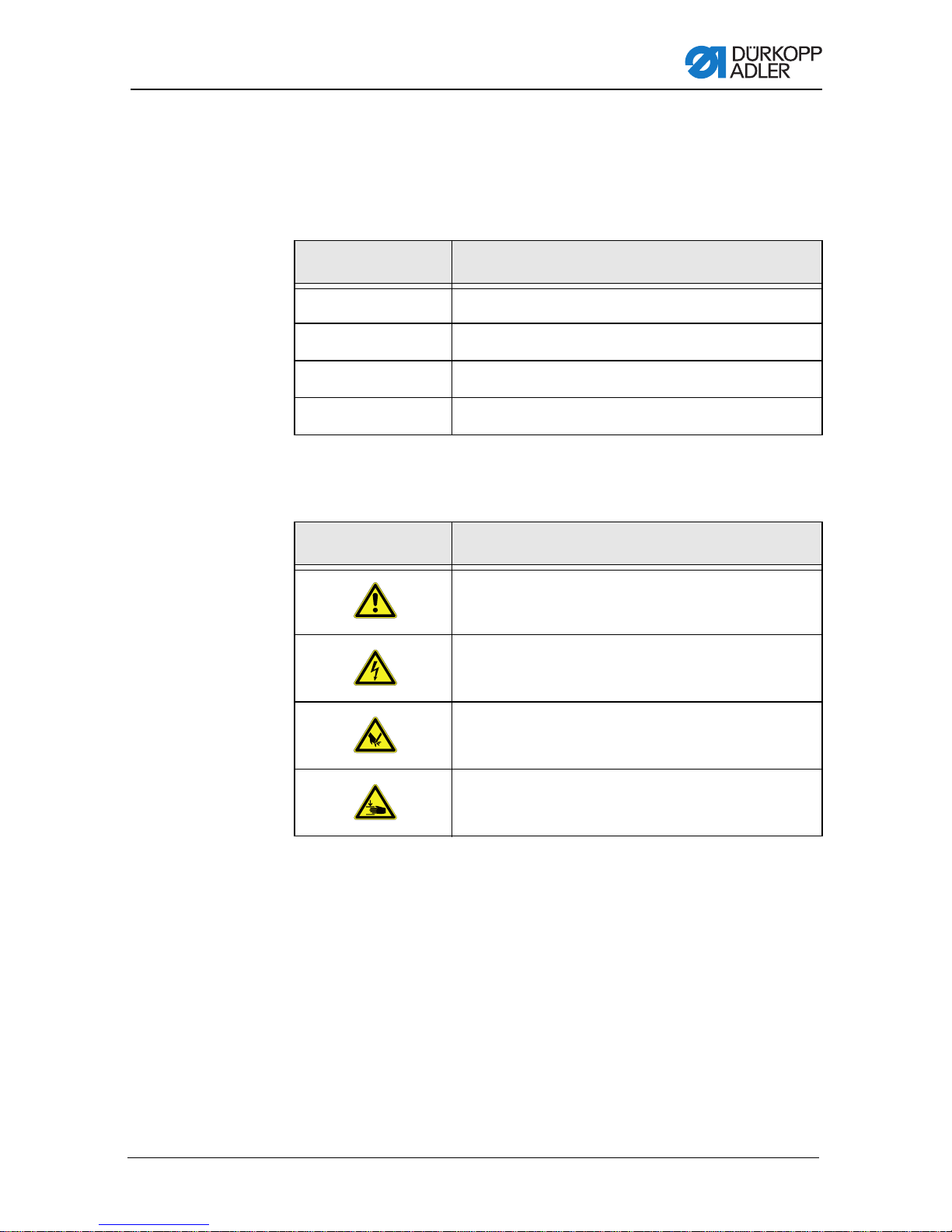
The following symbols indicate the type of risk to personnel:
Signal word Type of risk
General risk
Risk of electric shock
Risk of puncture injuries from pointed objects
Risk of crushing
Operating manual 969 - 00.0 - 08/2014 13
Page 16

Safety information
Examples of safety information layout in manual:
DANGER
Type and source of risk
Consequences of non-observance
Measures for avoiding the risk
This is what a warning looks like for a hazard that
will result in serious injury or even death if ignored.
WARNING
Type and source of risk
Consequences of non-observance
Measures for avoiding the risk
This is what a warning looks like for a hazard that
can result in serious injury or even death if ignored.
WARNING
Type and source of risk
Consequences of non-observance
Measures for avoiding the risk
This is what a warning looks like for a hazard that
can result in moderate or light injury if ignored.
NOTE
Type and source of risk
Consequences of non-observance
Measures for avoiding the risk
This is what a hazard note looks like for a hazard that can
result in property damage if the note is not observed.
ENVIRONMENTAL PROTECTION
Type and source of risk
Consequences of non-observance
Measures for avoiding the risk
This is what an environmental protection note looks
like for a hazard that could result in environmental
damage if the note is not observed.
14 Operating manual 969 - 00.0 - 08/2014
Page 17
Machine Description
①
②
③
④
⑤
⑥
⑦
⑧
⑨
⑩
⑪
⑫
⑬
⑭
⑮
⑯
⑰
⑱
⑲
⑳
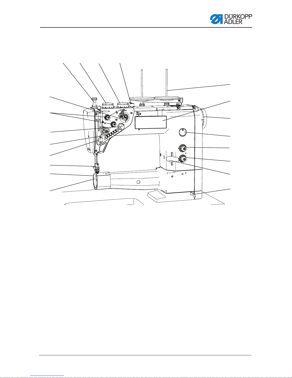
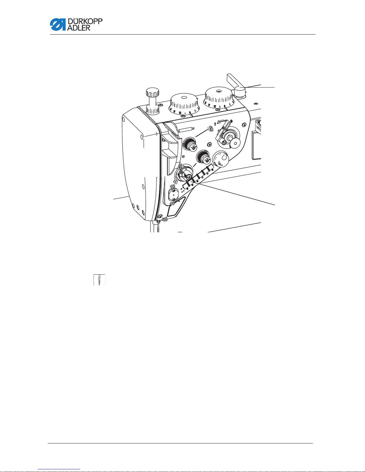
(1) - Hand lever
(2) - Adjusting wheel for the increased sewing foot stroke
(3) - Adjusting wheel for the normal sewing foot stroke
(4) - Adjusting wheel for the sewing foot pressure
(5) - Bobbin winder for the hook thread
(6) - Thread tensioners
(7) - Electroni c ha ndwheel
(8) - Keypad on the machine arm
(9) - Thread clamp
(10) - Sewing foot with needle
(11) - Hook
(12) - Cover
(13) - Locking lever for the machine head in the working position
(14) - Stitch adjustment lever
(15) - Adjusting wheel fo r the larger stitch length
(16) - Adjusting wheel for shorter stitch length
(17) - Sight glass for the oil level
(18) - Handwheel
(19) - OP 1000 control panel
(20) - Thread reel holders
4 Machine Description
Fig. 1: General overview – part 1
Operating manual 969 - 00.0 - 08/2014 15
Page 18
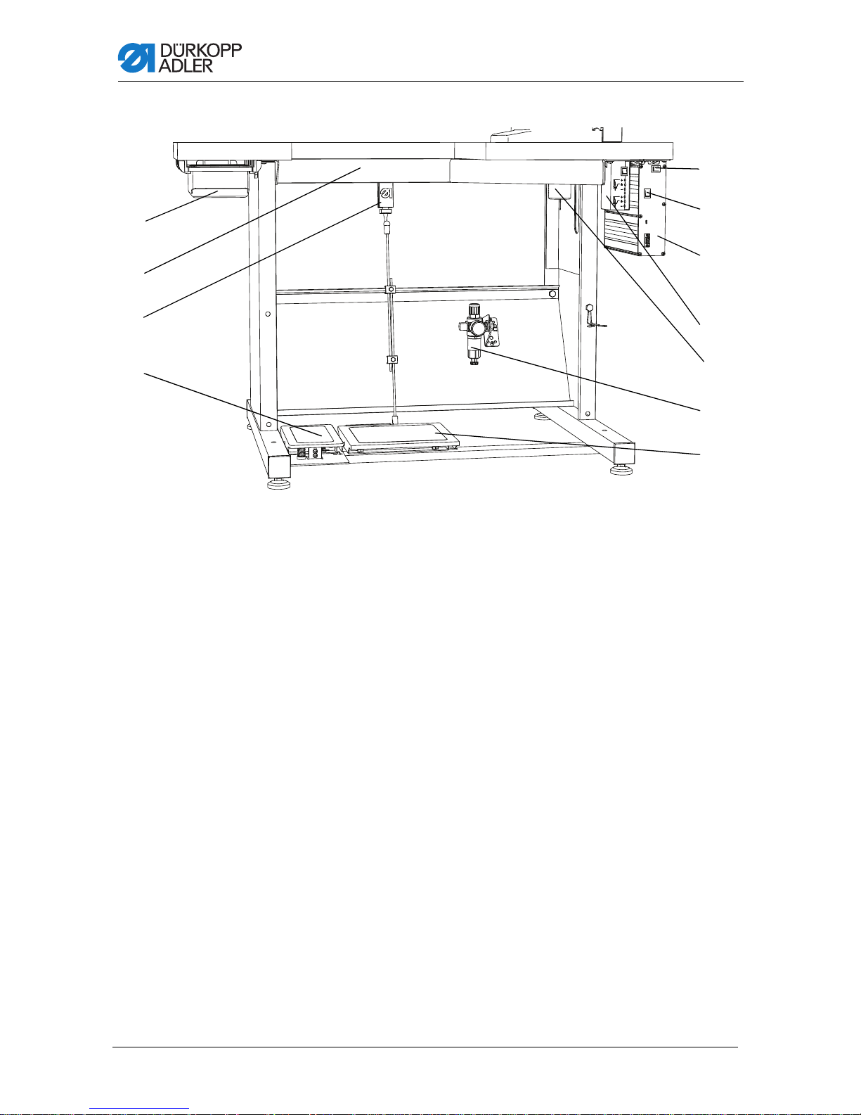
Fig. 2: General overview – part 2
①
②
⑤
⑥
⑦
⑩
⑨
⑧
③
④
⑪
(1) - Drawer
(2) - Plate bracket
(3) - Setpoint transducer
(4) - Foot switch
(5) - Operating pedal
(6) - Maintenance unit
(7) - Oil container for used oil
(8) - Sewing lamp transformer
(9) - DAC control unit
(10) - Main power switch
(11) - Switch for the sewing lamp
Machine Description
16 Operating manual 969 - 00.0 - 08/2014
Page 19
Machine Description
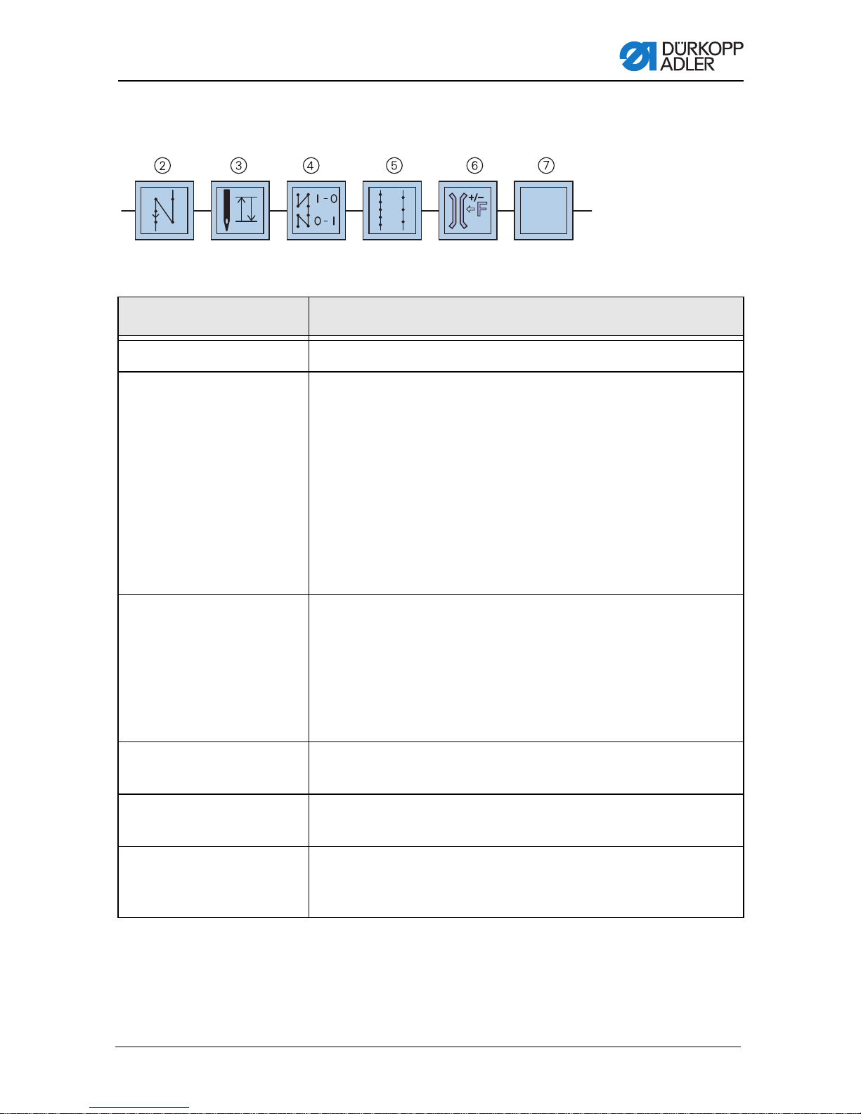
Function key assignment
Fig. 3: Function keys
Key Function
Reverse sewing key (2) When this key (2) is activated, the machine sews in reverse.
Needle positioning
key (3)
Start and end bar tack
key (4)
Stitch length key (5) When this key (5) is selected, the machine sews with the larger
When this key(3) is activated, the needle moves to a specific
position. This position is individually defined by the setting of the
parameters.
The machine is supplied configured so that activating key (3) will
raise the needle.
There are two needle positions that can be defined via the
control unit, one for the position when stopping during sewing of
the seam and one for the position after ending the seam
Needle positioning, page 33).
(
You can use key (3) to manually switch from one position to the
other.
The key (4) disables the basic setting for sewing the start and
end bartacks. When reverse sewing is set then the key (4)
suppresses further reverse sewing. If reverse sewing is nit
enables then pressing the key (4) will initiate another reverse
sewing. For information on the general settings for sewing start
and end bartacks read the
basic/classic control unit.
stitch length set on the upper stitch adjusting wheel.
Operating Manual for the DAC
Key for the additional
thread tension (6)
Key for an additional
function associated with
optional equipment (7)
Operating manual 969 - 00.0 - 08/2014 17
The key (6) switches on the additional thread tension.
Using the machine's electronic control unit, this key can be
assigned to activate any optional equipment. For example,
a needle cooler.
Page 20

Machine Description
18 Operating manual 969 - 00.0 - 08/2014
Page 21
Operation
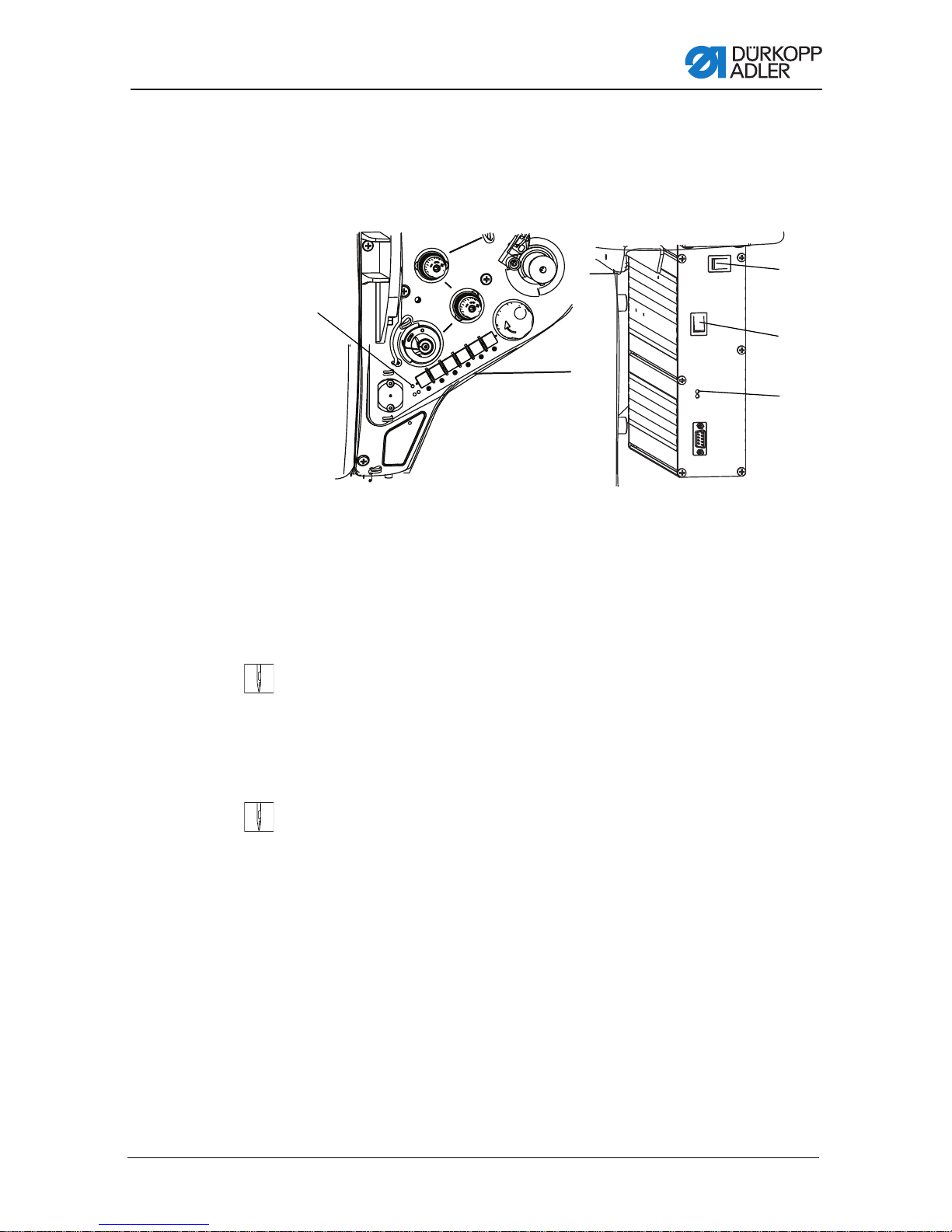
(1) - Indicator lamp on machine arm
(2) - Indicator lamp on the controller
(3) - Main power switch
(4) - Switch for the sewing lamp
①
②
③
④
5 Operation
5.1 Switching power supply on and off
Fig. 4: Switching power supply on and off
To switch power on:
1. Turn the power switch (3) to the I position.
Indicator lamps (1) and (2) illuminate.
To switch power off:
1. Turn the power switch (3) to the 0 position.
Indicator lamps (1) and (2) turn off.
Operating manual 969 - 00.0 - 08/2014 19
Page 22

Operation
5.2 Inserting and replacing needle
WARNING
Risk of injury from needle and moving parts.
Turn the sewing machine off before replacing the
needle.
Do not touch the tip of the needle.
Order
After switching to a different needle size, adjust the distance
between the hook and the needle ( Service manual).
ATTENTION
Damage to the machine, needle breakage, or thread dam-
age is possible due to incorrect distance between the needle and hook tip.
Check the distance to the hook tip after inserting a new needle
with a different size. Reset distance if necessary.
Incorrectly setting the needle height can damage the
machine.
Checking needle height is absolutely necessary when changing the needle for another system.
Incorrectly setting the allowance for clearance be tween
needle and hook tip can result in the following defects:
After inserting a thinner needle:
• Missing stitches
• Thread damage
After inserting a thicker needle:
• Damage to the hook tip
• Damage to the needle
20 Operating manual 969 - 00.0 - 08/2014
Page 23
Operation
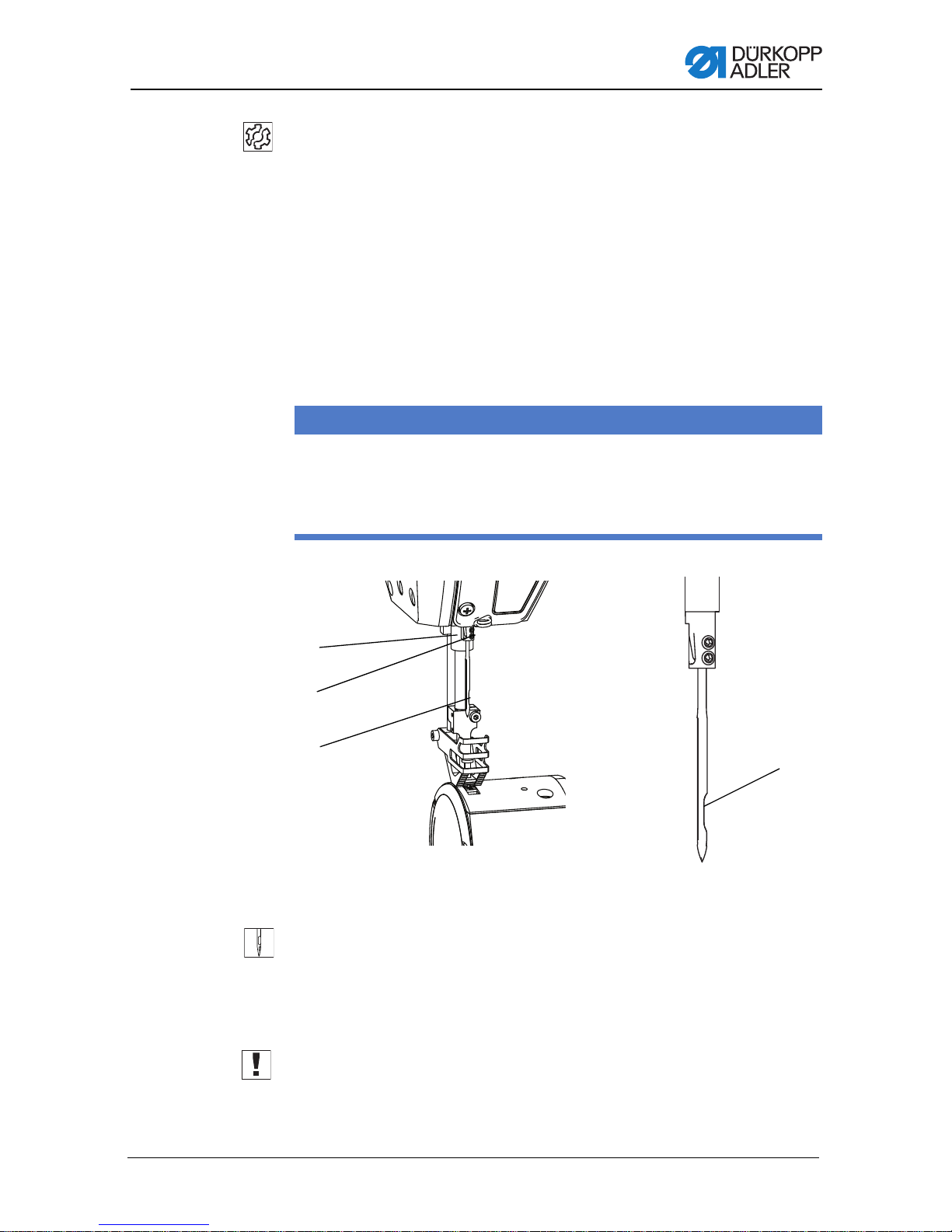
(1) - Needle bar
(2) - Fastening screws
(3) - Needle
(4) - Groove for the needle
④
③
②
①
Changing
the needle
Incorrectly setting needle bar height can result in the following malfunctions:
After inser ting a shorter needle:
• Damage to the hook tip
• Damage to the needle
After inserting a longer needle:
• Damage to the hook tip
• Damage to the needle
ATTENTION
Incorrect alignment of the needle can damage the
machine.
Make sure the hook tip does not come into contact with the
needle.
Fig. 5: Changing the needle
1. Turn handwheel until the needle (3) is at top dead center.
2. Loosen the screws (2).
3. Pull the needle (3) down and out.
4. Insert the new needle.
Operating manual 969 - 00.0 - 08/2014 21
5. Important: Align the needle so the groove in the needle shaft
6. Tighten the screws (2).
(4) is facing the hook and is parallel to the hook tip's direction
of movement.
Page 24

Operation
5.3 Threading the needle
WARNING
Risk of injury from needle and moving parts.
Turn off the sewing machine before threading the
thread.
5.3.1 Threading thread in reel holder
ATTENTION
An incorrect tube height causes the thread to wind onto
the needle tube resulting in irregular needle thread tension. This can result in an uneven seam and uneven thread
lengths after cutting!
Check that the tube height is set correctly.
On all submodels, the thread is fed through the machine from a
reel on a reel holder.
22 Operating manual 969 - 00.0 - 08/2014
Page 25

Operation
①
②
③
④
⑤
⑥
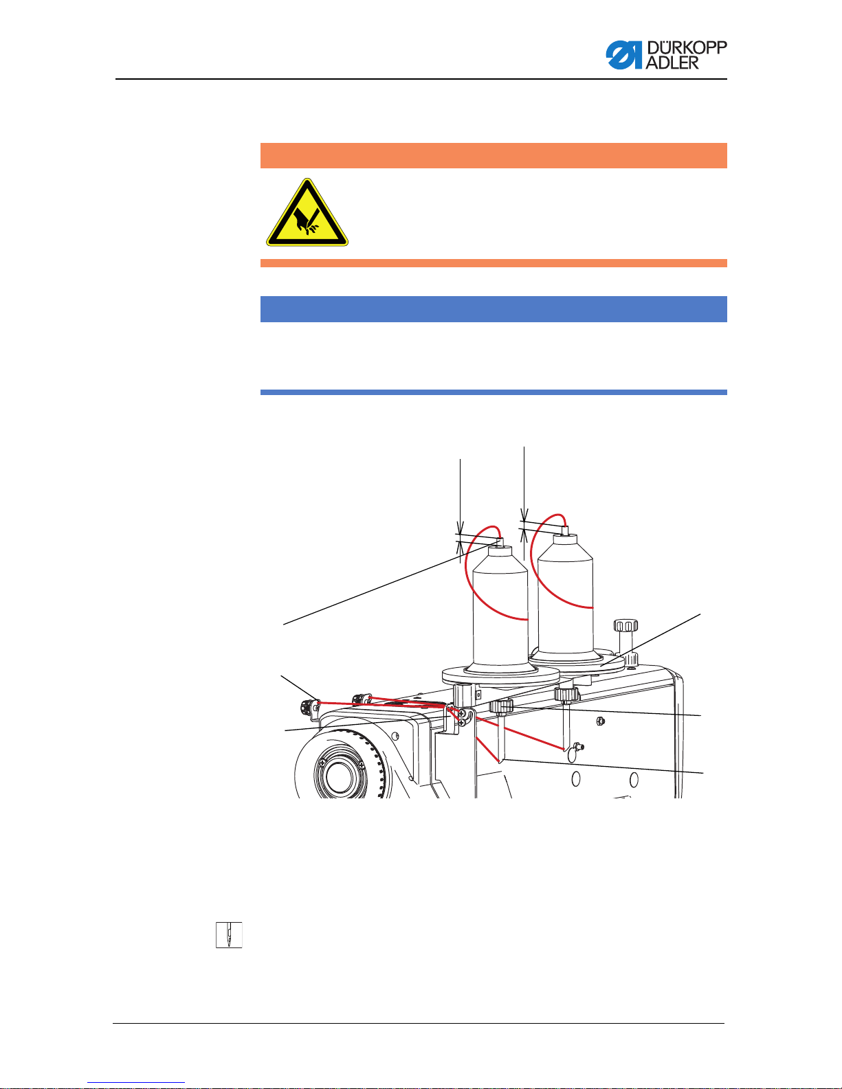
(1) - Thread guide
(2) - Hole in the pre- tensioner
(3) - Hole in the tube
(4) - Nut
(5) - Bobbin
(6) - Tube
10-15 mm
10-15 mm
Fig. 6: Threading thread in reel holder
1. Slide reel on bobbin (5)
2. Release the nut (4).
3. Important: Adjust the height of the tube (6) according to the
illustration, so that it projects 10 to 15 mm above the thread
bobbin.
4. Turn the tube so that the opening in the tube (3) faces the
thread guide (1).
5. Tighten the nut (4).
6. Feed the thread into the pipe (6), through the opening (3),
through the thread guide (1) and into the opening on the pretensioner (2).
Operating manual 969 - 00.0 - 08/2014 23
Page 26
5.3.2 Threading thread in machine
(1) - Hand lever for lifting presser foot
(2) - Positioning key
①
②
Fig. 7: Threading thread in machine
Operation
1. Lift presser foot with hand lever (1).
2. Use the positioning key (2) to set the upper needle position,
Needle positioning, page 33.
3. Turn off machine power switch.
24 Operating manual 969 - 00.0 - 08/2014
Page 27
Operation
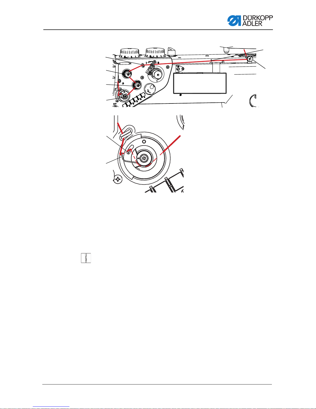
(1) - Thread guide
(2) - Additional tensioner
(3) - Primary tensioner
(4) - Balancing spring
(5) - Thread guide
(6) - Balancing spring arm
(7) - Preliminary tensione r
(8) - Thread guide
①
②
③
④
⑤
⑥
⑦
⑧
Fig. 8: Threading – part 1
4. Guide thread through the pre-tensioner (7).
5. Guide thread through guides (8)and (1).
6. Feed the thread counter-clockwise over the auxiliary tensioner (2).
7. Feed the thread clockwise over th e main tensioner (3).
8. Feed the thread into the thread guide (5): Feed the thread
clockwise and run around the axle of the balancing spring (4)
until the balancing spring arm( 6) turns and the thread moves
behind the thread guide (5).
Operating manual 969 - 00.0 - 08/2014 25
Page 28
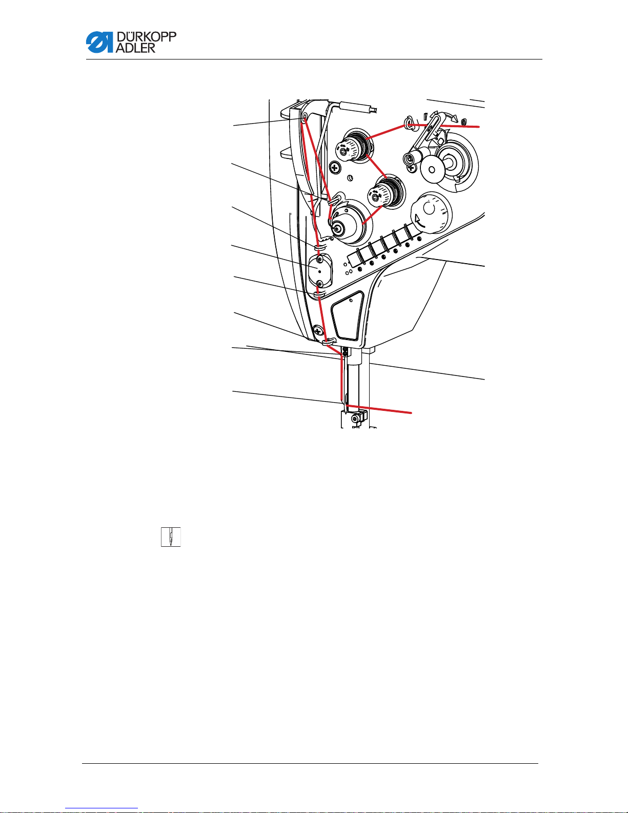
Fig. 9: Threading – part 2
(9) - Thread lever
(10) - Thread guide
(11) - Thread guide
(12) - Thread clamp
(13) - Thread guide
(14) - Thread guide
(15) - Thread guide on the needle bar
(16) - Needle eye
⑨
⑩
⑪
⑫
⑬
⑭
⑮
⑯
Operation
9. Feed the thread through thread guide (10).
10.Feed the thread through the eyelet of thread take-up lever (9).
11. Fee d the thread through the thread guide (11).
12.Feed the thread counterclockwise around the thread
clamp (12).
13.Feed the thread through the guides (13) and (14).
14.Pull the thread behind the thread guide so that it latches into
place in the thread clamp (12).
15.Feed the thread into the guide on the needle bar (15).
16.Feed the thread through the needle eye (16) from left to right.
26 Operating manual 969 - 00.0 - 08/2014
Page 29
Operation
10-15 mm
10-15 mm
①
②
③
④
⑤
⑥
(1) - Tube
(2) - Hole in the pre-tensioner
(3) - Thread guide
(4) - Hole in the tube
(5) - Nut
(6) - Bobbin
5.4 Threading and winding on the hook thread
WARNING
Risk of injury from needle and moving parts.
Turn off the machine before threading the thread.
ATTENTION
An incorrect height can cause the thread to wind onto the
tube!
Check that the tube height is set correctly.
Threading hook
thread
Fig. 10: Threading thread in reel holder
1. Slide reel on bobbin (6)
2. Release the nut (5).
Operating manual 969 - 00.0 - 08/2014 27
Page 30
Operation
(1) - Cutter
(2) - Thread guide
(3) - Tensioner
①
②
③
3. Important: Adjust the height of the tube (1) according to the
illustration, so that it projects 10 to 15 mm above the thread
bobbin.
4. Turn the tube so that the opening in the tube (4) faces the
thread guide (3).
5. Tighten the nut (5).
6. Feed the thread into the tube (1), through the opening (4),
through the thread guide (3) and into the opening on the pretensioner (2).
Fig. 11: Threading hook thread
7. Guide thread through tensioner (3).
8. Guide thread through thread guide (2).
9. Press the thread onto the tensioner (3) by hand, move the end
28 Operating manual 969 - 00.0 - 08/2014
of it underneath the cutter (1) and cut it by pulling it against
the blade of the cutter (1).
Page 31

Operation
(1) - Symbol for turning bobbin win de r on /o ff
(2) - Bobbin winder switch
(3) - Bobbin winder shaft
(4) - Bobbin
(5) - Bobbin driving pin
①
③
④
⑤
②
Winding Fig. 12: Winding hook thread
1. Place the bobbin (4) onto the bobbin winder shaft (3)and onto
2. Bring the bobbin winder to position I according to symbol (1)
Bobbin winder starts.
Once the bobbin winder starts, the thread will begin winding
automatically – the bobbin winder is driven by a separate motor.
You can still sew while the hook thread is winding.
Operating manual 969 - 00.0 - 08/2014 29
the bobbin driving pin (5).
by pressing the bobbin winder switch (2).
Page 32

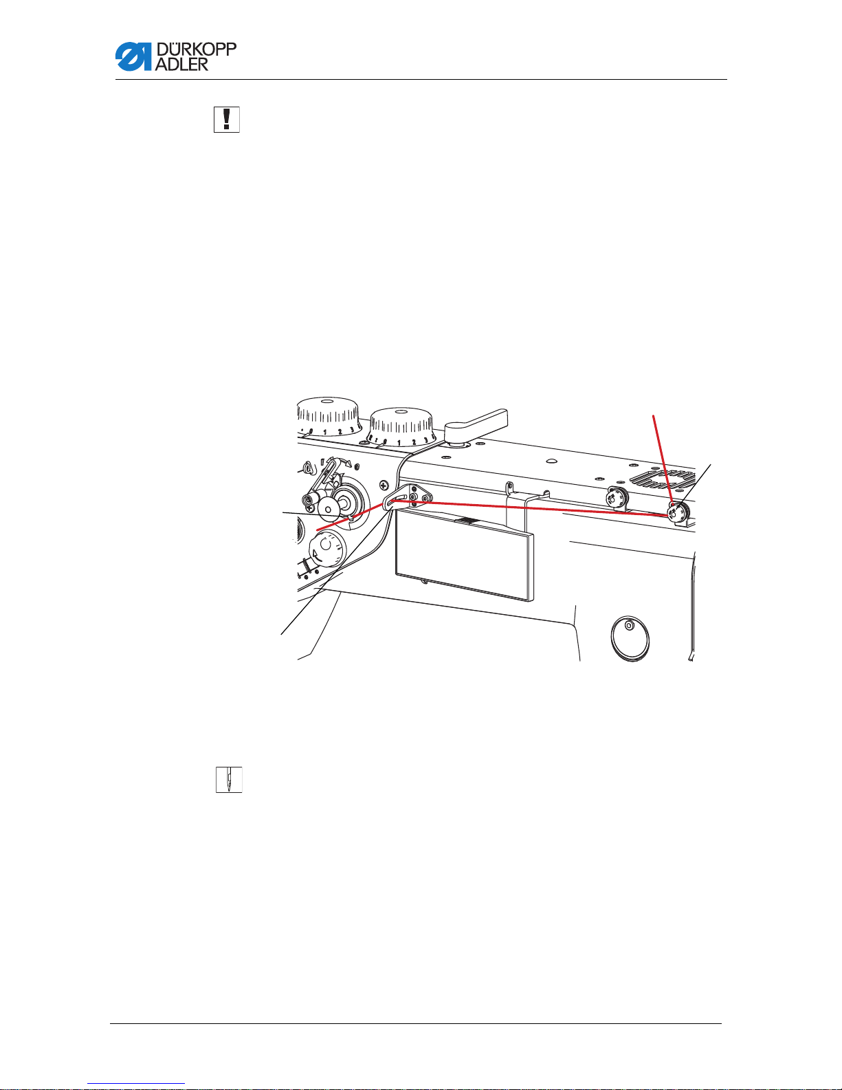
5.5 Replacing the hook thread bobbin
①
②
③
(1) - Thread end in needle
(2) - Cover
(3) - OP1000 control panel
WARNING
Risk of injury from needle and moving parts.
Turn off the sewing machine before replacing the
bobbin.
Fig. 13: Changing the hook thread bobbin
Operation
1. Press theF key on the OP1000 control panel (3).
The machine automatically turns to the position required for
2. Manually pull the needle thread out of the needle eye until the
3. Press the cover (2) at the position marked with an arrow until
An opening for replacing the hook thread bobbin opens.
30 Operating manual 969 - 00.0 - 08/2014
changing the hook thread bobbin. It is not possible to operate
the machine with the pedal at this time (Safe Stop).
end of the thread (1) is approx. 200 mm long.
it bends and can be turned.
Page 33

Operation
(1) - Flexible snap
(2) - Bobbin housing
①
②
Fig. 14: Replacing hook thread bobbin – part 1
4. Press on the elastic latc h (1).
The bobbin housing (2) tilts and the internal spring pushes
the bobbin housing (2) upwards.
Operating manual 969 - 00.0 - 08/2014 31
Page 34

Fig. 15: Replacing hook thread bobbin – part 2
(2) - Bobbin housing
(3) - Slo t in bo bb in housing
(4) - Pressure spring slot
(5) - Hook thread pressure spring
(6) - Hook thread bobbin
(7) - Bobbin hole
②
③
④
⑤
⑦
⑥
Operation
5. Remove the empty hook thread bobbin.
6. Insert the wound hook thread bobbin (6) with the bobbi n
hole (7) facing up.
7. Press on the bobbin housing (2) until the snap clicks into place.
8. Feed the end of the hook thread into the slot (5) under the
pressure spring (4) up to the slot (3).
Hold the hook thread bobbin with a finger while doing this.
9. Pull out the hook thread until 100 to 150 mm protrudes out of
the slot (3).
10.Place the opening cover for changing the hook thread back to
its original position.
1 1. Use your fingers to hold the end of the needle thread and turn
the handwheel until the needle disappears in the needle plate,
keep turning until the needle reappears and the thread lever
is at the top dead point.
12.Pull on the end of the needle thread and pull out the end of
the hook thread.
13.Cut both ends to approx. 70 mm by han d.
14.Press the F key again.
The machine is ready for use again.
32 Operating manual 969 - 00.0 - 08/2014
Page 35

Operation
(1) - Electronic handwheel
(2) - Key for positioning the needle
up/down
(3) - OP1000 control panel
(4) - Operating peda l
(5) - Belt cover
(6) - Handwheel
①
②
③
④
⑤
⑥
5.6 Needle positioning
The machine is equipped with manual, semi-automatic and automatic needle positioning.
WARNING
Risk of injury from needle and moving parts.
Protect yourself against accidents caused by the
needle tip and moving foot.
Fig. 16: Needle positioning
Operating manual 969 - 00.0 - 08/2014 33
Page 36

Operation
Manual needle positioning
Manual needle positioning is primarily intended for machine setup.
WARNING
Risk of injury from needle and moving parts.
Switch off the machine before manually positioning
the needle so that it cannot accidentally start during
the positioning procedure.
1. Raise the presser foot using the hand lever and remove any
material so the machine can run out.
2. Turn the handwheel (6) until the needle is correctly positioned.
Important: The correct direction of rotation is marked from
the back by an arrow on the belt cover (5).
Semi-automatic needle positioning
Works when the machine is on by using the electronic handwheel
(1) and is used to power the machine while the operating pedal
(4) is released.
Turning the electronic handwheel drives the machine using
the motor's torque. This allows you, e. g., to sew a seam to the
desired position without the risk of going too far.
1. Switch on the machine at the main switch.
Important: The electronic handwheel is not immediately activated once the machine is turned on. Therefore:
2. Activate the electronic handwheel (1) either with a one-quarter
turn or by briefly pressing the operating pedal forwards.
3. Turn the electronic handwheel (1) until the needle is correctly
positioned.
34 Operating manual 969 - 00.0 - 08/2014
Page 37

Operation
(1) - Identical needle thread and hook thread tension
(2) - Hook thread tension higher than needle thread tension
(3) - Needle thread tension higher than hook thread tens ion
①
②
③
Automatic needle positioning for seam start
The needle should be very close to the material before starting in
order to find the exact position for the start of the seam. In order
to adjust the needle height to the material thickness, the needle
can be slowly lowered downward by pressing on the electronic
handwheel (1) in the axis direction of the needle.
1. Press down on electronic handwheel (1).
2. Only let go once the tip of the needle is at the desired height.
3. Confirm the new setting by pressing down on the wheel again.
5.7 Thread tension
The tension of the needle thread and hook thread determines
where the thread interlaces.
Correct setting
The threads should normally interlace in the exact middle of the
material. When setting, typically only the tension of the needle
thread is altered, while the tension of the hook thread remains
unchanged.
Operating manual 969 - 00.0 - 08/2014 35
Page 38

Operation
(1) - Additional tensioner
(2) - Primary tensioner
(3) - Preliminary tensioner
①
②
③
Thread tension for decorative stitching
When using a decorative stitch, a thicker thread is normally used
with a relatively thinner material. Then the thread interlace is not
buried in the material.
In this instance, the tension is set so the threads interlace on the
back side – see (2).
5.7.1 Setting the needle thread tension
The 3 adjusting wheels on the tensioning screw triangle determine
the needle tension.
On the basic setting, the top side of one adjusting wheel is flush
with the screw in the middle.
Fig. 17: Setting the needle thread tension
General
To increase the tension:
1. Turn adjusting wheel clockwise.
To reduce the tension:
1. Turn adjusting wheel counterclockwise.
36 Operating manual 969 - 00.0 - 08/2014
Page 39

Operation
①
②
③
(1) - Additional te nsioner
(2) - Primary tensioner
(3) - Key on keypad for switching thread tension
(4) - Preliminary tensioner
④
Setting needle thread tension on Classic machines
On Classic machines, the key (3) can be used while sewing to
switch to a second thread tension, e.g. if different material should
be used in the middle of a seam.
Fig. 18: Setting needle thread tension on Classic machines
1. Set the tension on the pre-tensioner (4), sew a test seam and
cut the thread.
The end of the thread in the needle should be between
60 - 80 mm.
If the thread is shorter than this:
Gradually reduce the tension on the auxiliary tensioner until
the desired length is reached.
If the thread is longer than this:
Gradually increase the tension on the pre-tensioner until the
desired length is reached.
2. Press the key for switching thread tensio n ( 3) until th e LED
turns off.
The auxiliary tensioner (1) is automatically activated.
3. Sew the material requiring a lower needle tension and regulate
the tension on the main tensioner (2) until the correct thread
interlace is achieved.
4. Press the key (3) for switching the thread tension.
The key lights up and activates the auxiliary tensioner (1).
5. Sew the material requiring a higher needle tension and regu-
Operating manual 969 - 00.0 - 08/2014 37
late the tension on the main tensioner (1) until the correct
thread interlace is achieved.
Page 40

Operation
(1) - Additional tensioner
(2) - Primary tensioner
(3) - Preliminary tensioner
①
②
③
Adjusting the needle thread tension on Eco machines
On Eco machines, a second tension can be activated while
sewing. Thread tension is always the total tension of all three
tensioners.
Fig. 19: Adjusting the needle thread tension on Eco machines
1. Set the pre-tensioner (3) so the needle thread is slightly tensioned after it.
2. Set the auxiliary tensioner (1) so the tension it creates is
always much less than the tension created by the primary
tensioner (2).
ATTENTION
Risk of thread popping out if auxiliary tension is too high.
If the auxiliary tensioner (1) applies too much tension, the
thread can pop out of the auxiliary tensioner while sewing,
which suddenly reduces overall tension.
Make sure the auxiliary tensioner (1) is not set too high.
38 Operating manual 969 - 00.0 - 08/2014
Page 41

Operation
(1) - Bobbin housing
(2) - Hook thread
(3) - Adjusting screw
①
②
③
5.7.2 Setting hook thread tension
WARNING
Risk of injury from moving parts.
Turn off the machine before tensioning the hook
thread.
ATTENTION
Pulling the thread in the wron g direction while measuring
tension can result in incorrect tension measure ment
results.
Be sure to pull the thread in the proper direction.
ATTENTION
If the needle thread tensi on is too low, the tension of the
hook thread will also b e too low. At higher sewing speeds,
the needle thread will not be pulled properly and will get
stuck in the hook. This manifests itself through increased
noise and can result in damage to the machine.
Set the lower tension properly or reduce sewing speed.
Fig. 20: Adjusting the hook thread tension
Operating manual 969 - 00.0 - 08/2014 39
Page 42

Operation
1. Turn the handwheel until the bobbin housing (1) is in the illustrated position.
To increase the tension:
1. Turn the adjustment screw (3) clockwise (the 2 mm hexagonal
screwdriver included in the machine accessories can be used
for this).
To reduce the tension:
1. Turn the adjustment screw (3) counterclockwise.
The hook thread tension is set at the factory to 350 to 400 cN.
1cN = 1g
40 Operating manual 969 - 00.0 - 08/2014
Page 43

Operation
(1) - Balancing spring
(2) - Thread limiter
(3) - Direction to press when unlocking limiter
(4) - Limiter slot
(5) - Limiter hole
①
②
③
④
⑤
5.8 Setting thread limiter
WARNING
Risk to injury to finger from moving thread lever.
Turn off the machine before setting the thread limiter.
Together with the balancing spring, the thread limiter produces
suitable tension on the needle thread as it moves over the bobbin
housing. The thread is limited more when sewing thin material s
and less when sewing thick materials.
Correct setting:
The needle thread should be slightly tensioned when threading
the loop over the bobbin housing. Slight movement in the balancing spring indicates proper tensioning.
Fig. 21: Adjusting the thread limiter
Operating manual 969 - 00.0 - 08/2014 41
Page 44

Operation
1. Turn the thread limiter (2) in direction (3) until it moves to the
right side of the opening (5).
2. Move the thread limiter (2) into or ou t of the machine.
• For thin materials:
Move the thread limiter (2) out of the machine.
• For thick materials:
Move the thread limiter (2) into the machine.
3. Adjust the thread limiter (2) so that the slot (5) clicks into the
tensioning plate.
4. Sew to test whether or not the thread limiter setting is correct.
42 Operating manual 969 - 00.0 - 08/2014
Page 45

Operation
(+1) - Sewing position
(0) - Idle position
(-1) - Presser foot raised position
(-2) - Cutting and bar tacking position
(3) - Pedal
(4) - OP1000 control panel
③
④
(+1)
(0)
(-1)
(-2)
5.9 Raise the presser foot
The foot pedal is used while sewing to raise the presser foot, e.g.,
to move the material. The machine's electronic control unit allows
various operating modes to be preset.
Fig. 22: Pneumatically raising presser foot with pedal
ATTENTION
Risk of damage to machine from collision between needle
bar and presser foot.
Before raising the presser foot, use the electronic control
panel to position the needle in the upper or lower idle position.
Operating manual 969 - 00.0 - 08/2014 43
Page 46

Operation
Standard operating mode: The presser foot always remains
lowered.
1. Turn off keys (13) and (14) on the OP1000 control panel (4),
5.16 Operating the controller, page 63.
Their signal diodes turn off – see Operating manualfor
Basic/Classic DAC control panel.
2. Press the pedal (3) to position (-1).
P resser foot rises.
3. Release the pedal to position (0).
Presser foot lowers.
4. When a seam is complete, press the pedal to position (-2).
The machine cuts the thread and the presser foot rises.
5. Release the pedal to position (0).
Presser foot lowers.
ATTENTION
Avoid premature cutting of the thread before the seam is
finished through unintentional pressing of the pedal into
position -2.
Otherwise the seam will not be properly finished.
Operating mode: After completing the seam, the presser
foot rises automatically.
1. Press the key on the OP1000 control panel (4) to raise the
presser foot after the thread is cut.
Their signal diodes turn off – see Operating manualfor
Basic/Classic DAC control panel. Presser foot rises.
2. Press the pedal (3) to position (+1).
Presser foot lowers and machine starts up.
3. Release the pedal to position (0).
M achine stops.
4. Press the pedal to position (-1).
P resser foot rises.
5. Press the pedal to position (+1).
Presser foot lowers and machine starts up.
44 Operating manual 969 - 00.0 - 08/2014
Page 47

Operation
6. Press the pedal to position (–2).
Thread is cut and presser foot rises.
7. Release the pedal to position (0).
Presser foot remains raised until another seam is started.
Operating mode: Presser foot rises automatically every
time the machine stops.
1. Press both presser foot position keys on the OP1000 control
panel (4).
Their signal diodes light up – see Operating manualfor
Basic/Classic DAC control panel. Presser foot rises.
2. Press the pedal (3) to position (+1).
Presser foot lowers and machine starts up.
3. Release the pedal to position (0).
Machine stop s and presser foot automatically rises.
4. Press the pedal to position (+1).
Presser foot lowers and machine starts up.
5. Press the pedal to position (-2).
Thread is cut and presser foot rises.
6. Release the pedal to position (0).
Presser foot remains raised until another seam is started.
There is a time delay between starting the presser foot and the
machine starting in order to ensure the material is pressed by the
presser foot by the time sewing begins. This delay can be set
using operating parameters – see Operating manual for Basic/
Classic DAC control panel.
Operating manual 969 - 00.0 - 08/2014 45
Page 48

Operation
(0) - Hand lever at position 0
(1) - Hand lever at position 1
(2) - Hand lever at position 2
⓪
①
②
5.10Raising presser foot with hand lever
CAUTION
Risk of crushing when low ering the sewing foo t.
Make sure your hand is not underneath the presser
foot when it is lowered by the pedal or lever.
The presser foot can be manually raised when setting up the
machine or to remove the material from under the presser foot in
an emergency if the compressed air supply has been disconnected
from the machine.
Fig. 23: Raising presser foot with hand lever
Raising presser foot:
1. Turn the hand lever from position (0) to position (1).
Presser foot rises up to 14 mm above the needle plate and
2. Turn the hand lever to position (2).
Presser foot rises up to 20 mm above the needle plate and
46 Operating manual 969 - 00.0 - 08/2014
remains raised. The machine can be run at idle while in this
position.
remains raised.
Page 49

Operation
Lowering presser foot:
The presser foot can be lowered in two ways:
1. Manually turn hand lever to position(0).
2. Raise presser foot with pedal. Presser foot rises slightly, the
hand lever lock disengages and the internal spring moves the
hand lever back to position (0).
5.11Setting presser foot pressure
The adjusting wheel at the top left of the machine arm determines
the contact pressure of the sewing foot on the material to be sewn.
The pressure can be adjusted continuously by turning the adjusting wheel.
WARNING
Risk to injury to eyes.
Loosening the adjusting wheel too much can
cause it to unscrew and be shot off by the spring
underneath.
Never exceed a value of H = 55 mm, see fig. 24.
Correct setting
Set the pressure of the presser foot as low as possible, but high
enough so that the material can pass through evenly without
slipping through.
Defects due to incorrect setting
• Pressure too high:
Material is torn by the feed dogs. Feed is very loud.
• Pressure too low:
• Material slipping through causes an uneven stitch length.
• When moving up, the needle also takes some of the mate-
rial from the presser foot due to friction.
Operating manual 969 - 00.0 - 08/2014 47
Page 50

Fig. 24: Setting presser foot pressure
(1) - Adjusting screw
(2) - Counternut
(3) - Auxiliary spring
①
②
③
H
Operation
To increase presser foot pressure:
1. Release the counternut (2).
2. Turn adjusting wheel (1) to the right until the desired pressure
is reached.
3. If the pressure is insufficient even when the adjusting wheel
is fully tightened, use the auxiliary spring (3) provided in the
machine accessories.
4. Completely unscrew adjusting wheel (1).
WARNING
Risk to injury to eyes.
Loosening the adjusting wheel too much can
cause it to unscrew and be shot off by the spring
underneath.
Always loosen with the presser foot lowered (less
spring tension).
Loosen the screw with one hand, pressing down
with the other to prevent it from coming off.
48 Operating manual 969 - 00.0 - 08/2014
Page 51

Operation
ATTENTION
The auxiliary spring greatly increases pressure depending
on material thickness. This can cause defects when sewing soft material or sewing over thicker areas in the material.
If an auxiliary spring is not absolutely necessary due to the
presser foot rising when the needle moves up, do not use one.
5. Insert auxiliary spring (3).
6. Screw in adjusting screw (1) and adjust the presser foot pressure.
7. Tighten the counternut (2).
ATTENTION
The use of the auxiliary spring in conjunction with maxi-
mum machine speed can damage the machine.
Limit the maximum machine speed when using the auxiliary
spring.
Reducing pressure:
1. Release the counternut (2).
2. Turn adjusting wheel (1) to the left until the desired pressure
is reached.
ATTENTION
Unscrewing the adjusting wheel too far will damage the
machine.
A slot on this screw indicates the maximum distance that the
adjusting wheel may be unscrewed. This slot must never be
higher than the upper edge of the counternut (2).
3. Tighten the counternut (2).
Operating manual 969 - 00.0 - 08/2014 49
Page 52

Operation
5.12Setting presser foot stroke
The presser foot stroke has twelve levels of 1 mm each.
Correct presser foot stroke setting
Set the presser foot stroke as low as possible, but enough so that
the material can pass through evenly with a consistent stitch
length. In general, the thicker the material and the greater the
changes in thickness over the course of the seam, the higher the
pressure foot stroke should be.
Defects due to incorrect setting
• Stroke too high:
The heavy impact of the presser foot can damage the material and the machine is unusually loud.
• Stroke too low:
Stitch is shortened – its length is much shorter than the
length set by the adjusting wheel. Specifically, the machine
does not feed material properly at places where the material
thickness suddenly changes.
5.12.1 Limitation of sewing speed
If the pressure foot stroke is high, the operator must limit sewing
speed to the maximum RPM according to the table, regardless of
material, Table of maximum machine speeds, page 110.
ATTENTION
The machine can be da ma g ed if the sewing speed is too
high for the presser foot stroke.
Make sure the permitted sewing speed in the table in the
Appendix is not exceeded.
50 Operating manual 969 - 00.0 - 08/2014
Page 53

Operation
5.12.2 Limiting presser foot stroke
When the pressure foot contacts the material, dynamic force is
generated that increases with thinner and harder materials. This
force puts great strain on the machine and manifests itself through
noise. The operator can adjust the pressure foot stroke to suit the
material thickness according to the table, Table: Maximum
presser foot stroke, page 110.
ATTENTION
The machine can be damaged if the presser foot stroke is
too high for the thickness and hardness of the material.
Test presser foot stroke when sewing thinner materials and
reduce it accordingly.
5.12.3 Setting presser foot stroke
Classic machines have 2 adjusting wheels for adjusting the
presser foot stroke.
The left adjusting wheel (1) adjusts the normal presser foot stroke.
The right adjusting wheel (2) adjusts the increased presser foot
stroke.
Normal stroke is designed for high sewing speed. Increased stroke
is designed for sewing over thicker areas in the material. Eco
machines only have the left adjusting wheel.
Important: The increased presser foot stroke should not be lower
than the normal presser foo t stroke. The machi ne is designed so
the right adjusting wheel cannot set a lower stroke than the left
adjusting wheel.
ATTENTION
Machine can be damaged if the adjusting wheels are
forced.
Do not attempt to force the right adjusting wheel to set a lower
stroke than the left adjusting wheel.
Operating manual 969 - 00.0 - 08/2014 51
Page 54

Fig. 25: Presser foot stroke adjusting wheels
(1) -Adjusting wheel for the normal sewing foot stroke
(2) -Adjusting wheel for the increased sewing foot stroke
①
②
Operation
To increase presser foot stroke:
1. Turn adjusting wheel clockwise.
To reduce presser foot stroke:
1. Turn adjusting wheel counterclockwise.
52 Operating manual 969 - 00.0 - 08/2014
Page 55

Operation
(1) - Foot switch
①
5.12.4 Quickly switching presser foot st roke with foot
switch
If the machine is equipped with an optional foot switch, this can
be used to quickly switch the presser foot stroke between two
preset levels without having to stop sewing.
Fig. 26: Foot switch
Activating increased presser foot stroke
• Press foot switch (1) backwards with heel.
Increased stroke remains engaged as long as the foot switch
is depressed.
Deactivating increased presser foot stroke
• Release foot switch (1).
Operating manual 969 - 00.0 - 08/2014 53
Page 56

Operation
(1) - Key on keypad for sti tch length
(2) - Marks labeling selected stitch lengths
(3) - Bottom adjusting wheel for shorter stitches
(4) - Top adjusting whee l for the larger stitch length
①
②
③
④
5.13Stitch length
5.13.1 Setting stitch length
Depending on the equipment, the machine has 1 or 2 adjusting
wheels for stitch length.
The stitch length is continuously adjustable over a range of 0–
15 mm.
Fig. 27: Stitch length adjusting wheels
Top adjusting
wheel
Bottom adjust-
ing wheel
54 Operating manual 969 - 00.0 - 08/2014
To reduce stitch length:
1. Turn adjusting wheel clockwise.
To increase stitch length:
1. Turn adjusting wheel counterclockwise.
To reduce stitch length:
1. Turn adjusting wheel counterclockwise.
To increase stitch length:
1. Turn adjusting wheel clockwise.
Page 57

Operation
(1) – Stitch length key on keypad
(2) - Marks labeling selected stitch lengths
(3) - Bottom adjusting wheel for shorter stitches
(4) - Top adjusting whee l for the larger stitch length
①
②
③
④
5.13.2 Sewing with 2 stitch lengths
Fig. 28: Sewing with 2 stitch lengths
On machines with adjusting wheels for 2 stitch lengths, the top
adjusting wheel (4) is for longer stitch lengths and the bottom
adjusting wheel (3) is for shorter stitch lengths. The mark (2) on
the left of the adjusting wheel indicates the stitch length selected.
Important: The larger stitch length must not be shorter than the
smaller stitch length. Do not set a stitch length on the top adjusting
wheel (4) that is shorter than the stitch length on the bottom
adjusting wheel (3).
ATTENTION
Machine can be damaged if the adjusting wheels are
forced.
The machine is designed so the top adjusting wheel cannot
be set at a lower stitch length than the bottom adjusting wheel.
Do not attempt to force the top adjusting wheel to set a lower
stitch length.
Operating manual 969 - 00.0 - 08/2014 55
Page 58

Operation
①
②
③
④
⑤
(1) – Seam bar tacker key on keypad
(2) - OP1000 control panel
(3) - Foot switch
(4) - Operating pedal
(5) - Stitch adjustment lever
Switching stitch length:
Stitch length can be switched be tween the values set on the
adjusting wheels (3) and (4) while the machine is stopped or
running.
1. Press the key (1).
Stitch length switches from the current length to the second
length and the key illuminates/turns off. If the key illuminates,
the longer stitch length set on the top adjusting wheel (4) is
used.
5.13.3 Reverse sewing and seam bar tacking
On Eco machines, seam bar tacking can only be done by hand.
If desired, Eco machines can be retrofitted with an automatic bar
tacker. In all cases the seam bartacking can be activated when
the machine is stopped and also when the machine is running.
Fig. 29: Operating the seam bar tacker
56 Operating manual 969 - 00.0 - 08/2014
Page 59

Operation
Manual seam bar tacking:
1. Move stitch adjusting wheel (5) to the bottom.
The machine feeds the material in reverse as long as the
adjusting wheel is depressed.
Partially depressing the stitch adjustment lever (5) shortens the
stitch length in proportion to the distance of the adjustment lever
from its middle position.
In middle position, feed is stopped completely.
In the lower end position, the machine sews in reverse with the
stitch length currently set at the adjusting wheels.
Automatic seam bar tacking:
Only Classic machines come with semi-automatic and automatic
seam bar tacking. If desired, Eco machines can also be retrofitted.
Semi-automatic seam bar tacking:
1. Press key (1) on the machine keypad.
The machine feeds the material in reverse as long as the key
is depressed.
Semi-automatic seam bar tacking with foot switch
1. Press foot switch (3) forward with toes.
The machine feeds the material in reverse as long as the
foot switch is depressed.
Automatic seam bar tacking:
The machine's electronic control unit allows automatic seam bar
tacking to be activated.
To do this, read the Operating manual for the DAC basic/
classic control system.
Operating manual 969 - 00.0 - 08/2014 57
Page 60

Operation
1. Enter seam bartacking at the start of the seam and end of the
seam via the control panel (2).
2. Press operating pedal (4) down with toes.
Machine automatically sews a bar tack at the start of the
seam.
3. Finish the seam, then press the operating pedal (4) completely
backwards at the end of the seam.
Machine automatically sews a bar tack at the end of the
seam.
Selecting type of seam bar tacking and stitch count with
automatic seam bar tacking:
The machine's control unit allows selection between a single,
double or multiple (quadruple) bar tack. The type of bar tack
is selected using the keys on the OP1000 control panel – see
Operating manual for Basic/Classic DAC control unit.
Selecting seam bar tacking style with automatic seam bar
tacking:
Seams can be bar tacked either normally or decoratively.
Decorative style With a decorative seam bar tack, all forward and backward needle
stitches in the bar tack area go in the same needle holes while
sewing.
Normal style With a normal seam bar tack, the insertions can be offset from
one another. Since normal seam bar tacking is faster, the machine
is delivered with normal seam bar tacking preset by default.
The seam bar tacking style can be selected using the electronic
control panel parameters – see Operating manual for Basic/
Classic DAC control unit.
58 Operating manual 969 - 00.0 - 08/2014
Page 61

Operation
(1) - Auxiliary switch
Keys for:
(2) - Reverse sewing
(3) - Needle position
(4) - Start and end bar tack
(5) - Stitch length
(6) - Additional thread tension
(7) - Additional function (optional)
(8) - Screws for the assignment of
the additional swit ch (1)
①
②
③
④
⑤
⑦
⑧
⑥
5.14Quick functions on keypad
Depending on the submodel, the machine has a keypad on the
machine arm for activating specific functions while sewing.
5.14.1 Activating function keys
Fig. 30: Keypad for quick functions
Activating a key function
1. Press the key.
The function is activated. The key illuminates.
Deactivating a key function
1. Press the key again.
The function is deactivated. The key turns of f.
Operating manual 969 - 00.0 - 08/2014 59
Page 62

Operation
Fig. 31: Function keys
Key Function
Reverse sewing key (2) When this key (2) is activated, the machine sews in reverse.
Needle positioning
key (3)
When this key(3) is activated, the needle moves to a specific
position. This position is determined individually via the parameter settings.
The machine is supplied configured so that activating key (3) will
raise the needle.
There are two needle positions that can be configured on the
control unit for stopping during a seam and after a seam,
Needle positioning, page 33.
The key (3) allows the operator to manually switch from one
position to the other.
Start and end bar tack
key (4)
Stitch length key (5) When this ke y (5) is selected, the machine sews with the larger
Auxiliary thread tensioning key (6)
The key (4) disables the basic setting for sewing the start and
end bartacks. If bar tacks are on, pressing the key (4) skips the
next bar tack. If bar tacks are off, pressing the key (4) sews the
next bar tack. For the general setting for sewing start and end
bartacks, refer to the
classic control system.
stitch length set on the upper stitch adjusting wheel.
This key (6) activates the auxiliary thread tensioner.
Operating Manual fo r the DAC basic/
Auxiliary function key for
optional equipment (7)
60 Operating manual 969 - 00.0 - 08/2014
Using the machine's electronic control unit, this key can be
assigned to activate any optional equipment. For example, the
needle cooler.
Page 63

Operation
(1) - Auxiliary switch
(2) - Screw activates auxiliary switch
(3) - Original positio n
①
②
③
5.14.2 Transferring a key function to the auxiliary
switch
You can transfer one of the key functions to the auxiliary switch.
Select a function that you frequently use so that you can switch it
on faster while sewing.
Fig. 32: Keypad for quick functions
The key function is transferred by turning the screw under the key
until it is vertical.
Only one function can be assigned to the auxiliary switch (1). Thus,
only one screw can be set vertically.
All screws must be turned back to their original horizontal position
before transferring a new function.
Operating manual 969 - 00.0 - 08/2014 61
Page 64

Operation
(+1) - Sewing position
(0) - Idle position
(-1) - Presser foot raised position
(-2) - Cutting and bar tacking position
(3) - Pedal
(4) - OP1000 control panel
③
(+1)
(0)
(-1)
(-2)
To transfer a key function:
1. Bring all screws to their original positions (3), so that the slots
are horizontal.
2. Turn the screw under the desired key by 90° so that the slot
is vertical (2 threads and protection against separation)
5.15Thread cutting and securing against unrav-
eling
1. Press the pedal completely backwards to position (-2) at the
end of the seam.
If the machine was idle, it will perform a half or full rotation,
cut both threads and then stop.
Fig. 33: Cutting the thread
Cutting can also be started while the machine is running. In this
case, the machine first reduces speed when the pedal is pressed
back. Once the machine has reached cutting speed, the thread is
cut and the machine stops.
62 Operating manual 969 - 00.0 - 08/2014
Page 65

Operation
① ? ③ ④ ⑤ ⑥⑦⑧⑨⑩
⑪⑫⑬
⑭⑮⑯
Overview table provided below.
5.16Operating the controller
The machine is operated with the Basic/Classic DAC control unit.
Operating the controller is described in an individual Operating
Manual.
The Basic/Classic DAC operating manual is included in the control
unit pack. It can also be found in the "Downloads" section at
www.duerkopp-adler.com.
5.16.1 Control panel
The Basic/Classic DAC control unit is equipped with the OP1000
control panel.
Fig. 34: Control unit panel
Switch on/off function
1. Press the appropriate key.
Operating manual 969 - 00.0 - 08/2014 63
The LED on the key indicates the status.
Important: The functions on the machine only work if the proper
equipment is available.
Page 66

Overview of control panel functions
Key Function Status LED display
1 Thread cutter Off LED off
On LED on
2 Thread clamp Off LED off
On LED on
3 Start bar tack Off LED off
Single bar tack Lower right LED on
Double bar tack Both LEDs on
4 Multiple start bar tack Off LED off
On LED on
5 Soft start Off LED off
On LED on
6 End bar tack Off LED off
Operation
Single bar tack LED top left on
Double bar tack Both LEDs on
7 Multiple end bar tack Off LED off
On LED on
8 Reduced sewing speed
Input with +/- keys
9
nd
stitch length
2
Off LED off
On LED on
Off LED off
On LED on
10 Sewing program I Off LED off
On LED on
11 Sewing program II Off LED off
On LED on
12 Sewing program III Off LED off
On LED on
13 Light barrier Off LED off
On LED on
14 Presser foot rises after sewing stop Presser foot down LED off
15 Presser foot position after cutting the
thread
16 Needle position after sewing stop Needle down LED off
F Threading help
64 Operating manual 969 - 00.0 - 08/2014
Presser foot up LED on
Presser foot down LED off
Presser foot up LED on
Needle up LED on
Page 67

Operation
Key Function Status LED display
ESC Escape key, cancel
P Programming key Ready to be pro-
grammed
+ Increase the value
- Decrease the value
OK Confirmation
Reset Bobbin supply
LED on
Operating manual 969 - 00.0 - 08/2014 65
Page 68

Operation
(1) - Machine head
(2) - Swingable part of the table plate
(3) - Clamp
(4) - Fixed part of the table plate
①
②
④
③
5.17Swinging out the table plate
If the machine is equipped with a special frame, part of the table
plate can be folded down to create space under the lower arm for
sewing larger pieces.
WARNING
Risk of injury from moving parts.
Switch off the machine before swinging out the table
plate.
Fig. 35: Swinging out the table plate
1. Fold the machine head (1) to the rear in the direction of the
2. Release both clamps (3) fastening the folding part of the table
66 Operating manual 969 - 00.0 - 08/2014
arrow.
plate (2) to the fixed part of the plate (4).
Page 69

Operation
3. Slide the folding part of the table plate (2) approx. 10 mm to
the left and then fold it to the rear in the direction of the arrow .
4. Fold the machine head (1) back to the working position.
ATTENTION
When returning the folding part of the plate (2) back to the
normal working position, set the position of the clamps (3)
so that the plate is not damaged by colliding w ith the
clamps.
Operating manual 969 - 00.0 - 08/2014 67
Page 70

Operation
68 Operating manual 969 - 00.0 - 08/2014
Page 71

Maintenance
6 Maintenance
This section describes simple maintenance work that needs to be
carried out on a regular basis. This maintenance work can be
carried out by the operating personnel. Additional maintenance
work may only be performed by specially trained and qualified
technicians. The additional maintenance work is described in the
Service manual.
6.1 Cleaning the machine
Lint and thread remnants must be removed after every 8 hours of
operation, using a compressed-air pistol or a brush. When sewing
very fluffy materials the machine must be cleaned more often.
WARNING
Risk of injury from flying particles.
Turn off the power switch before cleaning.
Swirled up dirt particles can get into the eyes and
cause injury.
Hold the compressed-air pistol so that particles do
not fly toward persons.
Make sure no particles fly into the oil pan.
ATTENTION
Malfunctions can occur due to a dirty machine.
Lint and thread remnants can impair th e operation of the
machine.
Clean the machine at regular intervals according to the
instructions in the manual.
Operating manual 969 - 00.0 - 08/2014 69
Page 72

(1) - Area around the needle
(2) - Thread cutter
(3) - Feed-dog
(4) - Hook
(5) - Cover
(6) - Cover
①
②
③
④
⑤
⑥
Maintenance
Fig. 36: Areas requiring special attention when cleaning- Part 1
70 Operating manual 969 - 00.0 - 08/2014
Page 73

Maintenance
(7) - W ind e r cut ter
⑦
Fig. 37: Areas requiring special attention when cleaning- Part 2
Areas particularly susceptible to soiling:
• Winder cutter (7)
• Area between needle plate and feed dogs (3)
• Hook (4)
• Cutters (2), (5)
• Area around the needle (1)
Cleaning steps:
1. Shut off power by turning off power switch.
2. Unscrew needle plate.
3. Remove the covers (5) and (6) so that dust and thread
remnants can fall out of the normally covered openings.
4. Remove any lint and thread remnants using a compressed-air
pistol or a brush.
ATTENTION
Damage to the paintwork due to solvent-bas ed cleaners.
Solvent-based cleaners will damage paintwork on the
machine.
Only use solvent-free substances when cleaning the
machine.
Operating manual 969 - 00.0 - 08/2014 71
Page 74

Maintenance
6.2 Checking oil level
WARNING
Skin damage due to contact with oil.
Oil can cause a rash if it comes into contact with
skin.
Avoid any skin contact with the oil.
If oil gets on your skin, wash the affected areas
thoroughly.
ATTENTION
Machine damage possible due to in co rrect oil level.
Too little or too much oil can damage the machine.
Check the oil level on a daily basis, adding enough oil so oil
level is always between the minimum and maximum marks.
72 Operating manual 969 - 00.0 - 08/2014
Page 75

Maintenance
(1) - Filler opening
(2) - Maximum level marking
(3) - Minimum level marking
MAX
MIN
1
2
3
(1) - Filler opening
(2) - Maximum level marking
(3) - Minimum level marking
Fig. 38: Oil level indicator
1
2
MAX
MIN
3
Checking oil level
1. Check the oil level indicator every day:
Important: The oil level must always be between the minimum
level mark (3) and the maximum level mark (2).
Fig. 39: Oil level indicator
Refilling oil
Pour in oil through the filler opening (1) as required:
1. Switch off the sewing machine at the main power switch.
2. Top up the oil to the maximum level mark (2).
3. Press the power switch again to turn the sewing machine
CLASSIC
equipment
Note for machines with CLASSIC equipment:
On CLASSIC machines, if the oil level falls below the minimum
level marking (3), the oil level indicator lights up red.
1. Turn the sewing machine off, then on again after refilling oil.
The red light will turn off.
Operating manual 969 - 00.0 - 08/2014 73
back on.
Page 76

Maintenance
Required oil:
The machine should only be filled with DA10 lubricating oil or
equivalent, with the following properties:
• Viscosity at 40 °C: 10 mm²/s
• Flash point: 150 °C
ATTENTION
Machine damage possibl e du e to in correct oil.
An incorrect oil type can cause damage to the machine.
Only use oil specified in the operating manual.
ENVIRONMENTAL PROTECTION
Risk of environmental damage from oil.
Oil is a pollutant and must not enter the sewage
system or the soil.
Carefully collect waste oil and dispose of the waste
oil and oil-contaminated machine parts in the legally
prescribed manner.
74 Operating manual 969 - 00.0 - 08/2014
Page 77

Maintenance
0
2
8
4
6
10
1
2
(1) - Standard value: 6 bar
(2) - Pressure gage
6.3 Checking pneumatic system
ATTENTION
Machine damage possible due to incorrect pressu r e.
Incorrect pressure can result in damage to the machine.
Check the pressure on a daily basis.
Have the pressure adjusted by qualified specialists if the
pressure deviates from the reference value.
Fig. 40: Pressure indicator on maintenance unit
Check pressure:
1. Check the pressure and pressure gage (2) every day.
Standard value: 6 bar
Important: The pressure must never deviate from the
standard value by more than 1 bar.
Operating manual 969 - 00.0 - 08/2014 75
Page 78

Maintenance
(1) - Filter element
(2) - Water separato r
(3) - Drain screw
Water condensation will accumulate in the water separator of the
maintenance unit.
Fig. 41: Water level in the maintenance unit
6
4
8
2
10
0
1
2
3
Check water level:
1. Check the water level every day.
Important: Water condensation must not rise up to the filter
element (1).
ATTENTION
Machine damage possible if there is too much water.
Too much water can result in damage to the machine.
Check the water level every day and drain the condensation
water if there is too much water in the water separator.
Drain water as required:
1. Switch off the sewing machine at the main power switch.
2. Place the collection tray under the drain screw (3).
3. Remove the compressed air hose from the compressed air
supply .
4. Completely unscrew the drain screw (3)
5. Allow water to drain into the collection tray.
76 Operating manual 969 - 00.0 - 08/2014
Page 79

Maintenance
6. Re-tighten the drain screw (3).
7. Connect the compressed air hose to the compress ed ai r
supply .
8. Press the power switch again to turn the sewing machine
back on.
6.4 Customer Service
Contact for repairs if machine is damaged:
Dürkopp Adler AG
Potsdamer Str. 190
33719 Bielefeld, Germany
Phone: +49 (0) 180 5 383 756
Fax: +49 (0) 521 925 2594
Email: service@duerkopp-adler.com
Internet: www.duerkopp-adler.com
Operating manual 969 - 00.0 - 08/2014 77
Page 80

Maintenance
78 Operating manual 969 - 00.0 - 08/2014
Page 81

Installation
7 Installation
WARNING
Risk of injury.
The machine may only be set up by qualified
technicians.
7.1 Checking delivery
Important: The scope of delivery depends on the order.
Delivery consists of standard equipment and optional equipment.
1. Check that all parts are present before setup.
Stan da rd eq uipment:
• Machine upper section (1)
• Accessories – tools (not illustrated)
• Plate bracing (9)
• Lighting transformer (with the CLASSIC version) (11)
• DAC control unit (10)
• Thread reel holders (12)
• Connectors (not illustrated)
Optional equipment:
• Table plate (2)
• Drawer (3)
• Frame (4)
• Foot switch (6)
• Pedal (7)
• Compressed air regulator unit (8)
• Lighting transformer (with the Eco version) (11)
Operating manual 969 - 00.0 - 08/2014 79
Page 82

Fig. 42: Scope of delivery
(1) - Machine upper section
(2) - Table plate
(3) - Drawer
(4) - Frame
(5) - Setpoint transducer
(6) - Foot switch
(7) - Pedal
(8) - Compressed air regulator unit
(9) - Oil pan
(10) - DAC control unit
(11) - Lighting transformer
(12) - Thread reel holder
①
③
④
⑤
⑥
⑩
⑨
⑧
⑪
⑫
②
⑦
Installation
7.2 Removing transport securing devices
All transport securing devices must be removed prior to setup.
1. Remove the lashing straps and wooden blocks from the upper
machine section, table and frame.
2. Remove the support wedges between the machine arm and
needle plate.
80 Operating manual 969 - 00.0 - 08/2014
Page 83

Installation
(1) - Head sections of the inner bars
(2) - Inner bars
(3) - Frame bars
(4) - Cross bars
(5) - Adjusting screw
(6) - Frame foot struts
(7) - Cross strut
(8) - Oil can holder
①
③
④
⑤
⑥
⑦
②
⑧
7.3 Assembling the frame
Two different types of frame can be supplied with the machine,
depending on the version ordered:
• Standard frame with fixed table plate
• Special frame with partially swingable table plate
The frame can be supplied assembled or dismantled.
7.4 Assembling the standard frame
7.4.1 Assembling frame components
Fig. 43: Assembling frame components
1. Screw the cross bars( 4) to the frame bars (3).
2. Screw the oil can holder (8) to the frame bar (3).
3. Screw the cross strut (7) to the foot struts (6).
Operating manual 969 - 00.0 - 08/2014 81
Page 84

Installation
(1) - Hinge connecting rod
(2) - Lighting transformer
(3) - Setpoint transducer
(4) - Oil pan
(5) - Drawer
(6) - Frame mounting holes
(7) - Cable duct
(8) - Screw-mounted power cable
mounting clamp
(9) - Nailed mounting clamps
(10) - DAC control unit
①
③
④
⑤
⑥
②
⑦
⑧
⑩
⑨
4. Screw the inner bars (2) to the frame bar (3) so that both
headpieces (1) are at the same height.
5. Important: Turn th e adjustment screw (5) so the frame is
standing evenly on the floor.
7.4.2 Assembling components on underside of table
plate
The table plate is optional.
If you wish to manufacture your own table plate then use the
drawing provided in the appendix, Drawings for creating table
plate, page 105.
Fig. 44: Assembling components on underside of table plate
82 Operating manual 969 - 00.0 - 08/2014
1. Turn the table plate over so the underside is facing up.
2. Fasten the components as shown in the image. The position
of each component is to scale on the drawing, Component
layout on underside of table plate, page 107.
Page 85

Installation
(1) - Foot switch
(2) - Frame
(3) - Setpoint transducer
(4) - Pedal connecting rod
(5) - Pedal
①
②
④
⑤
③
3. Fasten the power cable mounting clamp (8) screws.
4. Nail down the cable clamps (9).
5. Pre-drill the holes in the plate for mounting the frame (6)
according to the drawing, Component layout on underside
of table plate, page 107.
If the machine is equipped with a sewing lamp, first connect the
sewing lamp transformer to the control unit, Connecting the
lighting, page 95. Then screw the control unit to the table plate
(the connection terminal is only accessible when the control unit
is removed).
7.4.3 Mounting the frame on the table plate and
mounting the pedal
Fig. 45: Mounting frame and pedal
1. Screw the frame (2) at the pre-drilled holes.
2. Screw the foot switch (1) to the vertical cross bar of the frame,
3. Screw on the pedal (5).
Operating manual 969 - 00.0 - 08/2014 83
as close as possible to the left bar.
Page 86

Installation
(1) - Table plate
(2) - Frame height adjustment screws
(3) - Pedal
(4) - Pedal connecting rod couplings
①
②
④
③
4. Connect the lugs on the ends of the connecting rod (4) to the
ball pins on the sensor (3) and pedal (5).
7.4.4 Setting frame height and pedal position
WARNING
Risk of occupational illness (musculoskeletal
damage) to operating personnel from failure to
comply with ergonomic requirements.
Adjust the frame height to the height of the person
operating the machine.
Position the pedal so that the middle of the pedal
lies in the axis of the needle with a maximum
deviation of 15 mm.
The frame can be adjusted continuously to any height between
770 and 910 mm.
Fig. 46: Setting frame height and pedal position
84 Operating manual 969 - 00.0 - 08/2014
Page 87

Installation
WARNING
Risk of crushing
Loosening the screws on the lower frame bars can
result in the table plate collapsing under its own
weight. This is more likely if the upper machine
section has already been mounted.
Make sure your hand does not get crushed while
loosening the screws.
1. Loosen the adjustment screws (2) on the frame bars.
2. Set the table plate (1) to the desired height.
Important: Use a tape measure to make sure the table plate
is level.
3. Tighten the screws (2) on the frame bars.
4. Set pedal (3) so that the middle is directly in line with the
needle – Mounting the frame on the table plate and
mounting the pedal, page 83.
5. Use the pedal connecting rod (4) couplings to set the angle as
desired by the machine operator.
Operating manual 969 - 00.0 - 08/2014 85
Page 88

Installation
(1) - Suspension screw with eyelet
(2) - Machine upper secti on
(3) - Table plate
(4) - Fastening screws
(5) - Oil hose with end piece
(6) - Fabric washer
①
②
④
③
⑤
⑥
7.4.5 Placing the machine upper section on the frame
Fig. 47: Placing the machine upper section on the frame
CAUTION
Risk of crushing
The upper machine section is very heavy.
Make sure your hands do not get crushed while
mounting the upper machine section.
1. Remove the plug from the top of the upper machine section
(2) and screw in the suspension screw with eyelet (1) included
in the machine accessories.
86 Operating manual 969 - 00.0 - 08/2014
Page 89

Installation
WARNING
Risk of injury.
The eyebolt is only designed for lifting the machine
head. Lifting the entire machine including the frame
via this eyebolt is not permitted.
2. Lift the machine upper section with a crane and, from below,
screw on the hose with the end piece (4) and the fabric washer
(5) included in the machine accessories.
3. Lower the machine upper section (2) onto the table plate (3)
and fasten using the screws (4) included in the machine
accessories.
Operating manual 969 - 00.0 - 08/2014 87
Page 90

7.5 Assembling the special frame
(1) - Rear bar plate
(2) - Table plate folding holder
(3) - Upper left side pl ate
(4) - Holder for the setpoint trans-
ducer
(5) - Plate holder hinge
(6) - Oil can holder
(7) - Rear cross bar
(8) - Hinge for the left side plate
(9) - Front cross bar
(10)- Lower left side plate
(11)- Cross strut
(12)- Adjustment support
(13)- Side plates of the frame bar
(14)- Head piece
①
③
④
⑤
⑥
⑦
②
⑧
⑨
⑩
⑪
⑫
⑬
⑭
7.5.1 Assembling frame components
Fig. 48: Assembling frame components
Installation
1. Screw both frame bar plates (13) to the rear bar plate (1) and
2. Screw on the head piece (14).
3. Screw on the rear cross bar (7) and screw in all screws in the
4. Screw on the plate holder hinge (5) including the folding table
88 Operating manual 969 - 00.0 - 08/2014
the front cross bar (9) and the lower left side plate (10) using
only the lower screws and screw these tight.
rear bar plate (1).
plate holder (2).
Page 91

Installation
(1) - Pins
(2) - Buffer
(3) - Fastening clamps for the high
voltage connection
(4) - Drawer
(5) - Fastening clamps
(6) - Lighting transfor mer
(7) - DAC control unit
①
③
②
④
⑤
⑥
⑦
5. Screw on the hinge for the upper left side plate (8).
6. Screw on the holder for the setpoint transducer (4).
7. Turn the frame with the underside upwards and screw the cross
bar (11) to the frame si de plates.
8. Important: Set the adjustment support (12) so that the frame
stands level on the floor.
9. From the rear, screw on the oil can holder (6).
7.5.2 Assembling components on underside of table
plate
The table plate is optional.
If you wish to manufacture your own table plate then use the
drawing provided in the appendix, Drawings for creating table
plate, page 105.
Fig. 49: Assembling components on underside of table plate
1. Turn the table plate over so the underside is facing up.
2. Hammer in the pin (1).
1. Fasten the components as shown in the image. The position
Operating manual 969 - 00.0 - 08/2014 89
of each component is to scale on the drawing, Component
layout on underside of table plate, page 107.
Page 92

Installation
(1) - Holes for fastening the machine
upper section to the fram e
(2) - Table plate folding holder
(3) - Left side plate
(4) - Knee switch
(5) - Setpoint transducer
(6) - Pedal connecting rod
(7) - Foot switch
(8) - Pedal
①
②
④
⑤
③
⑥
⑦
⑧
2. Fasten the power cable mounting clamp (3) screws.
3. Fasten the cable clamps (5) with nails.
If the machine is equipped with a sewing lamp, first connect the
sewing lamp transformer to the control unit, Connecting the
lighting, page 95. Then screw the control unit to the table plate
(the connection terminal is only accessible if the control unit is
removed).
7.5.3 Mounting the frame on the table plate and
mounting the pedal
Fig. 50: Mounting the frame on the table plate and mounting the pedal
1. Turn the table plate over so the underside is facing up.
2. Screw the left side plate (3) and the folding holder of the table
90 Operating manual 969 - 00.0 - 08/2014
plate (2) to the plate so that the holes for fastening the machine
upper section (1) lie in the same axis as the holes in the table
plate.
Page 93

Installation
3. Screw on the foot switch (7) as close as possi b l e to the left
side plate (3).
4. Screw on the pedal (8) as close as possible to the foot switch
(7). If the machine is equipped with a pedal then the middle of
the pedal must lie in the axis of the needle.
5. Screw the setpoint transdu cer (5) onto the holder.
6. Install the pedal connecting rod (6) and the move the pedal
ball pin holder so that the connecting rod lies in the axis of the
setpoint transducer (5).
7. Screw on the knee switch (4).
Operating manual 969 - 00.0 - 08/2014 91
Page 94

Installation
(1) - Eyebolt
(2) - Machine upper secti on
(3) - Table plate
(4) - Fastening screws
(5) - Holder for the reservoir
(6) - Used oil reservoir
(7) - Front frame bar pla te
(8) - Oil hose with end piece
(9) - Fabric washer
①
②
④
③
⑤
⑥
⑦
⑧
⑨
7.5.4 Placing the machine upper section on the frame
Fig. 51: Placing the machine upper section on the frame
CAUTION
Risk of crushing
The upper machine section is very heavy.
Make sure your hands do not get crushed while
mounting the upper machine section.
92 Operating manual 969 - 00.0 - 08/2014
Page 95

Installation
1. Remove the plug from the top of the upper machine section
(2) and screw in the eyebolt (1) included in the machine
accessories.
WARNING
Risk of injury.
The eyebolt is only designed for lifting the machine
head. Lifting the entire machine including the frame
via this eyebolt is not permitted.
2. Lift the machine upper section with a crane and, from below,
screw on the hose with the end piece (8) and the fabric washer
(9) included in the machine accessories.
3. Lower the machine upper section (2) onto the table plate (3)
and fasten using the screws (4) included in the machine
accessories.
4. Screw on the reservoir holder (5)
5. Screw on the used oil reservoi r (6).
6. Slide in the front frame bar plate (7) at an angle and screw in
place.
Operating manual 969 - 00.0 - 08/2014 93
Page 96

7.6 Assembling thread reel holder
(1) - Thread reel holder arm
(2) - Thread reel holder arm screws
(3) - Thread reel holder
(4) - Holes in thread reel holder
(5) - Thread reel holder screws
(6) - Machine upper section
①
③
④
⑤
②
⑥
Fig. 52: Assembling thread reel holder
Installation
1. Use the screws (5) included in the machine accessories. to
2. After loosening the screws (2) the thread reel holder arm (1)
94 Operating manual 969 - 00.0 - 08/2014
fasten the thread reel holders (3) to the machine upper
section (6).
can be tilted for operating the machine.
The thread reel holder arm (1) can also be slid into a lower
position and screw tight in the holes (4).
Page 97

Installation
7.7 Electrical connection
DANGER
Risk of death from electric shock.
The machine should only be connected to power by
qualified electricians.
Disconnect the power plug before carrying out w ork
on the electrical equipment.
Make sure the power plug is not accidentally
plugged back in.
The voltage on the type plate of the sewing drive
must correspond to the mains voltage.
7.7.1 Checking mains voltage
Important: The voltage on the type plate of the sewing drive must
correspond to the mains voltage.
1. Check mains voltage before connecting the machine.
7.7.2 Connecting the lighting
Connecting the transformer to the control unit
DANGER
Risk of death from electric shock.
Supply voltage for the sewing lamp remains on
even if the sewing machine is turned off through the
power switch.
Unplug the sewing machine before assembling and
connecting the sewing lamp to the transformer.
Make sure the power plug is not accidentally
plugged back in.
Operating manual 969 - 00.0 - 08/2014 95
Page 98

Installation
1. Remove the control unit (2)
2. Unscrew the cover (1).
3. Connect the cable as specified in the circuit diagram.
4. Screw on the cover (1).
7.7.3 Connecting control unit
DANGER
Risk of death from electric shock.
Disconnect the power plug before connecting the
control unit.
Make sure the power plug is not accidentally
plugged back in.
Connect the control unit as follows:
• Insert the plug of each connecting cable into the sockets on
the back of the control unit.
The sockets for each connector plug are labeled with
pictograms.
• Connect the control unit to the power supply using the power
cable.
Important: Read the Operating Manual for the eco/classic
DAC control unit.
The manual is included with the control unit.
The Operating Manual is also available in the document download
area at www.duerkopp-adler.com.
96 Operating manual 969 - 00.0 - 08/2014
Page 99

Installation
(1) - Cross bar
(2) - System connection hose
(3) - Maintenance unit
(4) - Machine hose
③
④
7.8 Connecting the pneumatic system
7.8.1 Fitting the maintenance unit
A pneumatic connection package for connecting the pneumatic
maintenance unit is available, Additional equipment, page 9.
It includes:
• System connection hose
(length 5 m, diameter 9 mm)
• Hose glands and couplings
• Connection plugs and sockets
Correct setting
The pressure in the pneumatic system network is 8 – 10 bar.
ATTENTION
Machine damage possible due to incorrect pressu r e.
Incorrect pressure can result in damage to the machine.
Make sure that the system pressure is set to 8 – 10 bar before
mounting the pneumatic system.
Fig. 53: Installing the maintenance unit pneumatic system
1. Attach the maintenance unit (3) to the upper cross bar (1) of
the frame using the bracket, screws and clip.
2. Plug the hose (4) coming out of the machine upper section
securely into the upper right of the maintenance unit (3).
3. Connect the system supply hose (2) to the pneumatic system.
Operating manual 969 - 00.0 - 08/2014 97
Page 100

Installation
0
2
8
4
6
10
(1) - Adjustment knob
(2) - Pressure gage
①
②
7.8.2 Setting operating pressure
Correct setting
The operating pressure of the pneumatic system is 6 bar.
ATTENTION
Machine damage possible due to incorrect pressu r e.
Incorrect pressure can result in damage to the machine.
Make sure the operating pressure is set correctly before
starting the machine.
Fig. 54: Setting operating pressure
1. Pull the adjustment knob (1) up.
2. Set the operating pressure so the pressure indicator (2) shows
3. Push the adjustment knob (1) down.
98 Operating manual 969 - 00.0 - 08/2014
6bar:
• To increase pressure: Turn the adjustment knob (1)
clockwise.
• To reduce pressure: Turn the adjustment knob (1)
counterclockwise.
 Loading...